US6181653B1 - Disc reproducing and recording apparatus with display of the amount of data in a buffer memory - Google Patents
Disc reproducing and recording apparatus with display of the amount of data in a buffer memory Download PDFInfo
- Publication number
- US6181653B1 US6181653B1 US08/267,579 US26757994A US6181653B1 US 6181653 B1 US6181653 B1 US 6181653B1 US 26757994 A US26757994 A US 26757994A US 6181653 B1 US6181653 B1 US 6181653B1
- Authority
- US
- United States
- Prior art keywords
- memory means
- disc
- memory
- data
- digital data
- Prior art date
- Legal status (The legal status is an assumption and is not a legal conclusion. Google has not performed a legal analysis and makes no representation as to the accuracy of the status listed.)
- Expired - Lifetime
Links
Images


Classifications
-
- G—PHYSICS
- G11—INFORMATION STORAGE
- G11B—INFORMATION STORAGE BASED ON RELATIVE MOVEMENT BETWEEN RECORD CARRIER AND TRANSDUCER
- G11B27/00—Editing; Indexing; Addressing; Timing or synchronising; Monitoring; Measuring tape travel
- G11B27/005—Reproducing at a different information rate from the information rate of recording
-
- G—PHYSICS
- G11—INFORMATION STORAGE
- G11B—INFORMATION STORAGE BASED ON RELATIVE MOVEMENT BETWEEN RECORD CARRIER AND TRANSDUCER
- G11B15/00—Driving, starting or stopping record carriers of filamentary or web form; Driving both such record carriers and heads; Guiding such record carriers or containers therefor; Control thereof; Control of operating function
- G11B15/18—Driving; Starting; Stopping; Arrangements for control or regulation thereof
-
- G—PHYSICS
- G11—INFORMATION STORAGE
- G11B—INFORMATION STORAGE BASED ON RELATIVE MOVEMENT BETWEEN RECORD CARRIER AND TRANSDUCER
- G11B19/00—Driving, starting, stopping record carriers not specifically of filamentary or web form, or of supports therefor; Control thereof; Control of operating function ; Driving both disc and head
- G11B19/02—Control of operating function, e.g. switching from recording to reproducing
- G11B19/04—Arrangements for preventing, inhibiting, or warning against double recording on the same blank or against other recording or reproducing malfunctions
-
- G—PHYSICS
- G11—INFORMATION STORAGE
- G11B—INFORMATION STORAGE BASED ON RELATIVE MOVEMENT BETWEEN RECORD CARRIER AND TRANSDUCER
- G11B20/00—Signal processing not specific to the method of recording or reproducing; Circuits therefor
- G11B20/00007—Time or data compression or expansion
-
- G—PHYSICS
- G11—INFORMATION STORAGE
- G11B—INFORMATION STORAGE BASED ON RELATIVE MOVEMENT BETWEEN RECORD CARRIER AND TRANSDUCER
- G11B20/00—Signal processing not specific to the method of recording or reproducing; Circuits therefor
- G11B20/10—Digital recording or reproducing
-
- G—PHYSICS
- G11—INFORMATION STORAGE
- G11B—INFORMATION STORAGE BASED ON RELATIVE MOVEMENT BETWEEN RECORD CARRIER AND TRANSDUCER
- G11B27/00—Editing; Indexing; Addressing; Timing or synchronising; Monitoring; Measuring tape travel
- G11B27/10—Indexing; Addressing; Timing or synchronising; Measuring tape travel
- G11B27/34—Indicating arrangements
-
- G—PHYSICS
- G11—INFORMATION STORAGE
- G11B—INFORMATION STORAGE BASED ON RELATIVE MOVEMENT BETWEEN RECORD CARRIER AND TRANSDUCER
- G11B27/00—Editing; Indexing; Addressing; Timing or synchronising; Monitoring; Measuring tape travel
- G11B27/36—Monitoring, i.e. supervising the progress of recording or reproducing
-
- G—PHYSICS
- G11—INFORMATION STORAGE
- G11B—INFORMATION STORAGE BASED ON RELATIVE MOVEMENT BETWEEN RECORD CARRIER AND TRANSDUCER
- G11B33/00—Constructional parts, details or accessories not provided for in the other groups of this subclass
- G11B33/10—Indicating arrangements; Warning arrangements
-
- G—PHYSICS
- G11—INFORMATION STORAGE
- G11B—INFORMATION STORAGE BASED ON RELATIVE MOVEMENT BETWEEN RECORD CARRIER AND TRANSDUCER
- G11B11/00—Recording on or reproducing from the same record carrier wherein for these two operations the methods are covered by different main groups of groups G11B3/00 - G11B7/00 or by different subgroups of group G11B9/00; Record carriers therefor
- G11B11/10—Recording on or reproducing from the same record carrier wherein for these two operations the methods are covered by different main groups of groups G11B3/00 - G11B7/00 or by different subgroups of group G11B9/00; Record carriers therefor using recording by magnetic means or other means for magnetisation or demagnetisation of a record carrier, e.g. light induced spin magnetisation; Demagnetisation by thermal or stress means in the presence or not of an orienting magnetic field
- G11B11/105—Recording on or reproducing from the same record carrier wherein for these two operations the methods are covered by different main groups of groups G11B3/00 - G11B7/00 or by different subgroups of group G11B9/00; Record carriers therefor using recording by magnetic means or other means for magnetisation or demagnetisation of a record carrier, e.g. light induced spin magnetisation; Demagnetisation by thermal or stress means in the presence or not of an orienting magnetic field using a beam of light or a magnetic field for recording by change of magnetisation and a beam of light for reproducing, i.e. magneto-optical, e.g. light-induced thermomagnetic recording, spin magnetisation recording, Kerr or Faraday effect reproducing
- G11B11/10502—Recording on or reproducing from the same record carrier wherein for these two operations the methods are covered by different main groups of groups G11B3/00 - G11B7/00 or by different subgroups of group G11B9/00; Record carriers therefor using recording by magnetic means or other means for magnetisation or demagnetisation of a record carrier, e.g. light induced spin magnetisation; Demagnetisation by thermal or stress means in the presence or not of an orienting magnetic field using a beam of light or a magnetic field for recording by change of magnetisation and a beam of light for reproducing, i.e. magneto-optical, e.g. light-induced thermomagnetic recording, spin magnetisation recording, Kerr or Faraday effect reproducing characterised by the transducing operation to be executed
- G11B11/10504—Recording
-
- G—PHYSICS
- G11—INFORMATION STORAGE
- G11B—INFORMATION STORAGE BASED ON RELATIVE MOVEMENT BETWEEN RECORD CARRIER AND TRANSDUCER
- G11B11/00—Recording on or reproducing from the same record carrier wherein for these two operations the methods are covered by different main groups of groups G11B3/00 - G11B7/00 or by different subgroups of group G11B9/00; Record carriers therefor
- G11B11/10—Recording on or reproducing from the same record carrier wherein for these two operations the methods are covered by different main groups of groups G11B3/00 - G11B7/00 or by different subgroups of group G11B9/00; Record carriers therefor using recording by magnetic means or other means for magnetisation or demagnetisation of a record carrier, e.g. light induced spin magnetisation; Demagnetisation by thermal or stress means in the presence or not of an orienting magnetic field
- G11B11/105—Recording on or reproducing from the same record carrier wherein for these two operations the methods are covered by different main groups of groups G11B3/00 - G11B7/00 or by different subgroups of group G11B9/00; Record carriers therefor using recording by magnetic means or other means for magnetisation or demagnetisation of a record carrier, e.g. light induced spin magnetisation; Demagnetisation by thermal or stress means in the presence or not of an orienting magnetic field using a beam of light or a magnetic field for recording by change of magnetisation and a beam of light for reproducing, i.e. magneto-optical, e.g. light-induced thermomagnetic recording, spin magnetisation recording, Kerr or Faraday effect reproducing
- G11B11/10502—Recording on or reproducing from the same record carrier wherein for these two operations the methods are covered by different main groups of groups G11B3/00 - G11B7/00 or by different subgroups of group G11B9/00; Record carriers therefor using recording by magnetic means or other means for magnetisation or demagnetisation of a record carrier, e.g. light induced spin magnetisation; Demagnetisation by thermal or stress means in the presence or not of an orienting magnetic field using a beam of light or a magnetic field for recording by change of magnetisation and a beam of light for reproducing, i.e. magneto-optical, e.g. light-induced thermomagnetic recording, spin magnetisation recording, Kerr or Faraday effect reproducing characterised by the transducing operation to be executed
- G11B11/10515—Reproducing
-
- G—PHYSICS
- G11—INFORMATION STORAGE
- G11B—INFORMATION STORAGE BASED ON RELATIVE MOVEMENT BETWEEN RECORD CARRIER AND TRANSDUCER
- G11B2220/00—Record carriers by type
- G11B2220/20—Disc-shaped record carriers
-
- G—PHYSICS
- G11—INFORMATION STORAGE
- G11B—INFORMATION STORAGE BASED ON RELATIVE MOVEMENT BETWEEN RECORD CARRIER AND TRANSDUCER
- G11B2220/00—Record carriers by type
- G11B2220/20—Disc-shaped record carriers
- G11B2220/25—Disc-shaped record carriers characterised in that the disc is based on a specific recording technology
- G11B2220/2525—Magneto-optical [MO] discs
-
- G—PHYSICS
- G11—INFORMATION STORAGE
- G11B—INFORMATION STORAGE BASED ON RELATIVE MOVEMENT BETWEEN RECORD CARRIER AND TRANSDUCER
- G11B2220/00—Record carriers by type
- G11B2220/20—Disc-shaped record carriers
- G11B2220/25—Disc-shaped record carriers characterised in that the disc is based on a specific recording technology
- G11B2220/2537—Optical discs
- G11B2220/2545—CDs
-
- G—PHYSICS
- G11—INFORMATION STORAGE
- G11B—INFORMATION STORAGE BASED ON RELATIVE MOVEMENT BETWEEN RECORD CARRIER AND TRANSDUCER
- G11B7/00—Recording or reproducing by optical means, e.g. recording using a thermal beam of optical radiation by modifying optical properties or the physical structure, reproducing using an optical beam at lower power by sensing optical properties; Record carriers therefor
- G11B7/004—Recording, reproducing or erasing methods; Read, write or erase circuits therefor
- G11B7/0045—Recording
-
- G—PHYSICS
- G11—INFORMATION STORAGE
- G11B—INFORMATION STORAGE BASED ON RELATIVE MOVEMENT BETWEEN RECORD CARRIER AND TRANSDUCER
- G11B7/00—Recording or reproducing by optical means, e.g. recording using a thermal beam of optical radiation by modifying optical properties or the physical structure, reproducing using an optical beam at lower power by sensing optical properties; Record carriers therefor
- G11B7/004—Recording, reproducing or erasing methods; Read, write or erase circuits therefor
- G11B7/005—Reproducing
Definitions
- the present invention relates to a disc reproducing apparatus and a disc recording apparatus for use with a magneto-optical disc driving apparatus that includes a memory in order to present a reproduced sound from being interrupted by an external vibration.
- CD players are known to reproduce a CD (compact disc) in which digital audio data is recorded on spiral tracks as rows of pits. Upon playback, the CD player reproduces a digital audio data by detecting that a laser beam radiated on and reflected from on the tracks of the disc is changed in intensity due to the existence of pits while rotating the disc at a constant linear velocity.
- the CD player can reproduce audio data without trouble according to error correction processing using an error detection code and an error correction code.
- a conventional vehicular CD player or portable CD player that tends to be causing the very large vibrations or impulses includes a mechanical vibration isolating mechanism in order to present the reproduced sound from being interrupted.
- a vibration isolating mechanism is not always sufficient and cannot suppress a reproduced sound from being interrupted depending on the magnitude of vibration or impulse.
- data stored in the semiconductor memory is utilized to present the mechanical external disturbance such as vibration, impulse or the like in the reproduced sound.
- the storage capacity of the semiconductor memory is limited so that, when the external disturbance takes place several times, a reproduced sound may be interrupted. Therefore, the user cannot discern the reason why the reproduced sound is interrupted, i.e., the reproduced sound might be interrupted because the function of the semiconductor memory is not operated correctly or because the semiconductor memory suffers from a load that exceeds a storage capacity thereof.
- a disc reproducing apparatus in which a signal recorded on a disc is optically read out from the disc and reproduced as an audio signal.
- This disc reproducing apparatus comprises an optical pickup tracing tracks formed on the disc to optically read out a signal recorded on the disc.
- the disc reproducing apparatus further includes a first decoding unit for decoding an output signal of the optical pickup and outputting the same at a first transfer rate.
- the disc reproducing apparatus further includes a memory in which digital data output from the first decoding unit is stored temporarily.
- the disc reproducing apparatus further includes a controller for controlling write and read of the memory such that the digital data is intermittently written in the memory at the first transfer rate and the digital data is continuously read out from the memory at a second transfer rate lower than the first transfer rate.
- the disc reproducing apparatus further includes a second decoding unit for decoding the digital data read out from the memory and outputting the same as an audio signal at the second transfer rate.
- the disc reproducing apparatus further includes a display device for displaying an amount of the digital data stored in the memory so that an increase or decrease of the amount of the digital data can be visually confirmed.
- a disc recording apparatus in which an input digital audio signal is encoded and recorded on a disc.
- This disc recording apparatus comprises a first encoding unit for compressing an input digital audio signal.
- the disc recording apparatus further includes a memory in which compressed data stored in the memory is temporarily stored.
- the disc recording apparatus further includes a second encoding unit for intermittently receiving the compressed data stored in the memory and outputting encoded data as recording data to be recorded on the disc at its predetermined position.
- the disc recording apparatus further includes a controller for controlling the memory such that the compressed data from the first encoding unit is continuously written in the memory and the compressed data stored in the memory is read out from the memory at every predetermined data amount.
- the disc recording apparatus further includes a display device for displaying a storage amount of the compressed data stored in the memory so that an increase or decrease of the amount of the compressed data can be visually confirmed.
- FIG. 1 is a block diagram showing an embodiment of a magneto-optical disc apparatus to which a disc reproducing apparatus and recording apparatus according to the present invention is applied;
- FIG. 2 is a schematic diagram used to explain operation of a DRAM (dynamic random access memory) shown in FIG. 1 in the recording mode;
- DRAM dynamic random access memory
- FIG. 3 is a schematic diagram used to explain operation of the DRAM shown in FIG. 1 in the playback mode
- FIG. 4 is a schematic representation used to explain operation of the DRAM shown in FIG. 1 in the playback mode
- FIG. 5 is a schematic diagram used to explain an example of a graphic pattern displayed on a display unit shown in FIG. 1;
- FIG. 6 is a schematic diagram used to explain another example of the graphic pattern displayed on the display unit shown in FIG. 1;
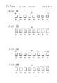
- FIGS. 7A and 7B are respectively diagrams used to explain an example of graphic pattern displayed by a fixed display element in FIG. 6 in the recording mode.
- FIGS. 8A and 8B are respectively diagrams used to explain another example of graphic pattern displayed by the fixed display element in FIG. 6 in the playback mode.
- FIG. 1 of the accompanying drawings shows in block form an arrangement of an embodiment of a magneto-optical disc apparatus to which the disc reproducing apparatus and recording apparatus according to the present invention is applied.
- a magneto-optical disc 2 is accommodated in a disc cartridge 3 .
- the magneto-optical disc 2 is rotated at a predetermined speed by a spindle motor 1 .
- An optical pickup 4 having an objective lens 6 is disposed under the magneto-optical disc 2 and a recording magnetic head 6 is disposed above the magneto-optical disc 2 in a confronting relation to the optical pickup 4 .
- the optical pickup 4 includes, in addition to the objective lens 5 , optical assembly parts such as a laser light source such as a laser diode or the like, a collimator lens for collimating a laser beam from the laser diode, a polarizing beam splitter for separating a reflected-back laser beam from the magneto-optical disc 2 from the laser beam traveling from the laser diode to the magneto-optical disc 2 , a cylindrical lens for processing the laser beam reflected from the magneto-optical disc 2 in an astigmatism fashion or the like, and a photodiode for detecting the laser beam reflected on the magneto-optical disc 2 or the like (components of the optical pickup 4 are not separately shown).
- a laser light source such as a laser diode or the like
- a collimator lens for collimating a laser beam from the laser diode
- a polarizing beam splitter for separating a reflected-back laser beam from the magneto-optical disc 2 from the laser
- a signal output from the photodiode (not shown) incorporated within the optical pickup 4 is input to an RF (radio frequency) amplifier 9 and thereby processed in a matrix fashion. Therefore, a focusing error signal based on an astigmatism method and a tracking error signal based on a push-pull method, for example, are generated from the RF amplifier 9 and then output to a servo control circuit 7 .
- the servo control circuit 7 comprises a focusing servo control circuit, a tracking servo control circuit, a spindle motor servo control circuit, a sled servo control circuit or the like (components of the servo control circuit 7 are not separately shown).
- the focusing servo control circuit effects the focusing servo on the optical system of the optical pickup 4 such that a focusing error signal becomes zero.
- the tracking servo control circuit effects the tracking servo on the optical system of the optical pickup 4 such that a tracking error signal becomes zero.
- the spindle motor servo control circuit controls the spindle motor 1 so that the spindle motor 1 rotates the magneto-optical disc 2 at a predetermined rotational speed.
- the sled servo control circuit controls a feeding motor 8 such that the optical pickup 4 and the magnetic head 6 are moved toward the magneto-optical disc 2 at its predetermined target track position specified by a system controller 18 .
- the servo control circuit 7 supplies the system controller 18 with information representative of operation conditions of respective parts that are controlled by the above respective servo control circuits.
- the RF amplifier 9 extracts from the output signal of the optical pickup 4 a signal corresponding to an address that was recorded on the magneto-optical disc 2 by wobbling the tracks and then outputs the same to an address decoder 11 .
- the address decoder 11 decodes an address from the input signal and outputs the decoded address to an encoder/decoder 10 .
- the RF amplifier 9 further supplies the encoder/decoder 10 with an RF signal and an a MO (magneto-optical) signal corresponding to the signal recorded on the magneto-optical disc 2 .
- the encoder/decoder 10 demodulates the MO signal or RF signal input from the RF amplifier 9 in an eight-to-fourteen system and also error-corrects the same.
- the MO signal or RF signal thus processed is stored in a DRAM (dynamic random access memory) 14 that is served as a vibration-isolating memory through a memory controller 13 .
- the DRAM 14 has a storage capacity of 4 Mbits, for example, and this storage capacity of the DRAM 14 corresponds to an audio signal having a duration of 12 seconds.
- Data read out from the DRAM 14 is supplied through the memory controller 13 to an encoder/decoder 15 for compressing and expanding an audio signal, in which it is decoded and then fed to a 16-bit digital-to-analog (D/A) converter 16 .
- Data, thus converted in the form of digital to analog data by the D/A converter 16 is output to a speaker (not shown) as an audio output.
- the encoder/decoder 15 includes a system that is disclosed in Japanese Laid-Open Patent Publication No. 3-112221.
- the audio signal can be compressed and expanded by the encoder/decoder 15 at high-efficiency without deteriorating the sound quality.
- An analog audio signal output from a microphone or tuner is supplied to a 16-bit analog-to-digital converter 17 , in which it is converted into digital audio data and then supplied to the encoder/decoder 15 , thereby being timebase-compressed to 1 ⁇ 5, for example.
- the audio data thus compressed by the encoder/decoder 15 is supplied through the memory controller 13 to the DRAM 14 , in which it is stored temporarily.
- Data read out from the DRAM 14 is supplied to the encoder/decoder 10 , in which it is added with an error-correction code and modulated in the EFM method and then fed to a head driver circuit 12 .
- the head driver circuit 12 drives the magnetic head 6 in response to the input signal.
- the system controller 18 is a microcomputer that comprises a CPU (central processing unit) for controlling operation of respective portions, a ROM (read-only memory) in which a control program used by the CPU is stored in advance, a RAM (random access memory) in which various data are stored temporarily and an I/O (input/output) interface through which various data are exchanged between the CPU and the external apparatus.
- a CPU central processing unit
- ROM read-only memory
- RAM random access memory
- I/O input/output
- the system controller 18 is connected to a key input operation unit 20 that is operated to input various operations.
- a display unit 19 that displays thereon operation conditions of respective portions.
- the key input operation unit 20 includes a mode selection key for switching the vibration isolating mode and the normal mode, in addition to fundamental operation keys such as a play key, a stop key or the like.
- the system controller 18 controls respective portions to set the recording mode.
- the analog audio signal input to the A/D converter 17 is converted into digital audio data in which one sample is formed of 16 bits and then fed to the encoder/decoder 15 for compressing the audio data.
- the encoder/decoder 15 timebase-compresses the input digital data to 1 ⁇ 5 in accordance with a predetermined rule.
- Digital data thus timebase-compressed by the encoder/decoder 15 is supplied though the memory controller 13 to the encoder/decoder 10 .
- the encoder/decoder 10 adds predetermined error-detection and error-correction codes to the input digital data and modulates the same in the EFM fashion.
- a signal encoded by the encoder/decoder 10 is supplied to the head driver circuit 12 and the head driver circuit 12 drives the recording magnetic head 6 in response to the encoded signal supplied thereto. Therefore, a magnetic field (of N or S polarity) is applied to the magneto-optical disc 12 in response to recording data.
- the system controller 18 controls the optical pickup 4 through the servo control circuit 7 so that the laser diode (not shown) incorporated in the optical pickup 4 generates a laser beam.
- This laser beam is radiated on and converged on the magneto-optical disc 2 through the objective lens 5 .
- An intensity of this laser beam is set to a value that holds the magneto-optical disc 2 at a temperature higher than a Curie temperature. Hence, data is recorded on the magneto-optical disc 2 in a magneto-optical fashion.
- the magneto-optical disc 2 When data is recorded on the magneto-optical disc 2 , the magneto-optical disc 2 is rotated by the spindle motor 1 at a predetermined speed.
- the servo control circuit 7 drives the feed motor 8 to move the optical pickup 4 along the radial direction of the magneto-optical disc 2 , whereby an information recording point is moved to a predetermined track on the magneto-optical disc 2 .
- the system controller 18 controls respective portions to set the playback mode.
- the servo control circuit 7 controls the optical pickup 4 so that the intensity of the laser beam emitted from the laser diode is set to be a value smaller than that in the recording mode. Therefore, even when radiated with the laser beam, the magneto-optical disc 2 can be prevented from being heated to greater than the Curie temperature and the recorded data can be prevented from being erased. Thus, the recorded data can be reproduced reliably.
- the RF amplifier 9 separates the MO signal from the output signal output by the optical pickup 4 and supplies the MO signal to the encoder/decoder 10 .
- the encoder/decoder 10 demodulates the input MO signal in an EFM fashion and error-corrects and error-detects the same.
- Data decoded by the encoder/decoder 10 is supplied through the memory controller 13 to the encoder/decoder 15 .
- the encoder/decoder 15 timebase-expands the input data five times so that the input data recovers its original timebase.
- Digital data decoded by the encoder/decoder 15 is supplied to a digital-to-analog (D/A) converter 16 , in which it is converted in the form of a digital to analog signal and supplied to a speaker or the like as the original analog audio signal.
- D/A digital-to-analog
- the recording operation on the magneto-optical disc 2 is not started until recording data of a predetermined amount is collected.
- the analog audio signal to be recorded is input continuously, the recording operation on the magneto-optical disc 2 is effected intermittently.
- digital audio data, intermittently reproduced from the magneto-optical disc 2 is timebase-expanded five times by the encoder/decoder 15 and output as a consecutive analog audio signal.
- the system controller 18 controls the memory controller 13 so that data to be recorded on the magneto-optical disc 2 or data reproduced from the magneto-optical disc 2 is temporarily stored in the DRAM 14 . Other operations are similar to those in the normal mode. The writing and reading of data in and from the DRAM 14 will be described below.
- the memory controller 13 controls the writing and reading of data in and from the DRAM 14 as shown in FIG. 2 .
- W depicts a write pointer
- R depicts a read pointer.
- the memory controller 13 continuously increments a write pointer W at speed corresponding to a data write and transfer rate (bit rate) to write data supplied from the encoder/decoder 15 in the DRAM 14 as shown in FIG. 2 .
- a read pointer R is incremented intermittently at speed corresponding to a data read-out transfer rate (higher than the write transfer rate). Then, the recorded data is read out from the DRAM 14 by k and then supplied to the encoder/decoder 10 .
- the system controller 18 controls the optical pickup 4 through the servo control circuit 7 so that the optical pickup 4 is repeatedly set in the standby mode until the position of the recording point reaches the predetermined position. Then, data can be continuously (not always continuously) recorded on successive tracks on the magneto-optical disc 2 .
- the DRAM 14 can constantly keep the data writing area larger than a predetermined amount so that, when the recording point is displaced from the correct position due to the external disturbance or the like, the system controller 18 detects such displacement of the recording point (displacement of the recording point can be detected by monitoring address data output from the address decoder 11 ). At that time, the servo control circuit 17 controls the optical pickup 4 so as to interrupt the recording operation on the magneto-optical disc 2 .
- the recording When the address is returned to the position at which the recording is interrupted, the recording is re-started. While the analog audio signal to be recorded is continuously input while the recording point is returned, such analog audio data is recorded in a vacant area of the DRAM 14 , thereby preventing the recording data from overflowing and being interrupted.
- the memory controller 13 controls the DRAM 14 as shown in FIG. 3 . More specifically, the memory controller 13 intermittently increments the write pointer W of the DRAM 14 at speed corresponding to a high transfer rate (speed corresponding to the read-out transfer rate in the recording mode) to write reproduced data, which was reproduced from the magneto-optical disc 2 and supplied thereto from the encoder/decoder 10 , in the DRAM 14 . Further, the memory controller 13 continuously increments the read pointer R at speed corresponding to a low transfer rate (speed corresponding to the write transfer rate in the recording mode), whereby data written in the DRAM 14 is read out and supplied to the encoder/decoder 15 .
- the writing on the DRAM 14 is stopped. Then, the amount of data written in the DRAM 14 (i.e., amount of data written in the area between the write pointer W and the read pointer R) becomes less than a predetermined amount L, the writing on the DRAM 14 is resumed.
- the writing on the DRAM 14 i.e., reproduction from the magneto-optical disc 2 ) is carried out intermittently.
- the system controller 18 urges the optical pickup 4 to be placed in the standby mode at the predetermined position when the playback operation is not carried out, similarly to the recording mode.
- the system controller 18 detects such displacement of the reproducing point and temporarily interrupts the reproducing operation of data from the magneto-optical disc 2 . Then, the system controller 18 monitors an address decoded by the address decoder 11 and moves the reproducing point to the original position. When the reproducing point is returned to the original position, the playback operation is resumed from the original position of the reproducing point. Data is continuously read out from the DRAM 14 until the reproducing point is returned to the original position, thereby preventing the audio signal output from the A/D converter 16 from being interrupted.
- FIG. 4 of the accompanying drawings schematically shows operation of the DRAM 14 upon playback.
- data reproduced from the magneto-optical disc 2 is intermittently reproduced from the magneto-optical disc 2 at a transfer rate of 1.4 Mbit/second, for example, and temporarily written in the 4M bit-DRAM 14 .
- Data written in the DRAM 14 is read out from the DRAM 14 at a transfer rate of 0.3Mbit/second and supplied to the encoder/decoder 15 .
- the encoder/decoder 15 timebase-expands the input data about five times and continuously outputs the thus processed data to the D/A converter 16 at a transfer rate of 1.4Mbit/second.
- the storage capacity of 4M bits of the DRAM 14 is equivalent to the reproducing time period of about 12 seconds so that, even when the reproducing point is shifted from the correct position due to the external disturbance or the like, if the reproducing point is returned to the original position within 12 seconds, then a reproduced sound can be prevented from being interrupted.
- the display unit 19 displays a message corresponding to the storage amount of the DRAM 14 under the control of the system controller 18 .
- fixed display elements C 1 , C 2 which express a container that urges the user to remember the storage capacity of the DRAM 14
- variable display elements D 1 , D 2 , . . . , D 15 and T disposed at the positions encircled by the fixed display elements C 1 , C 2 so as to display data amount (amount of data to be written) stored in the DRAM 14 .
- the leftmost portion in FIG. 5 indicates an example of display that an amount of data stored in the DRAM 14 is zero.
- the rightmost portion in FIG. 5 indicates an example of display showing the condition such that data are written in the DRAM 14 at its full storage capacity.
- the graphic pattern shown in FIG. 5 is not displayed on the display unit 19 in FIG. 1 .
- the vibration isolating mode is selected, the fixed display elements C 1 , C 2 representative of the containers that urges the user to remember the storage capacity of the DRAM 14 shown on the left end of FIG. 5 are displayed on the display unit 19 for the first time, whereafter the playback operation is started.
- playback data stored in the DRAM 14 is increased, only the variable display element T of the teardrop type is displayed initially.
- variable display elements D 15 and D 14 are displayed above the variable display element T that is disposed in the bottom of the container.
- the variable display elements D 13 , D 12 , D 11 are displayed above the variable display elements D 15 , D 14 .
- the number of variable display elements is increased in the upper direction from the bottom of the container.
- all the variable display elements T and D 15 to D 1 are displayed on the display unit 19 as shown on the right end of FIG. 5 .
- variable display element T blinks to let the user know that playback data is constantly passed through the DRAM 14 .
- An amount of data stored in the DRAM 14 can be conceptually explained with the image of “water in a bucket”, for example. That is, an amount of water corresponds to the amount of data. Since in the vibration isolating mode the variable display elements T and D 15 to D 1 are displayed within the fixed display elements C 1 , C 2 (buckets) which urge the user to remember the storage capacity of the DRAM 14 in response to the amount of data (water), the user can recognize the data amount relatively easily.
- the disc reproducing apparatus and recording apparatus cannot effect the function to prevent a reproduced sound from being interrupted.
- the graphic pattern shown on the left end of FIG. 5 is displayed on the display unit 19 , the user can visually confirm by the above displayed graphic pattern the state that the amount of data becomes zero. That is, the user can confirm from the change of the displayed graphic patterns shown in FIG. 5 that the DRAM 14 is operated effectively.
- the user can visually confirm that the reproduced sound is interrupted due to an external disturbance that exceeds the storage capacity of the DRAM 14 .
- the reproduced sound is interrupted under the condition such that the graphic pattern shown on the right end of FIG. 5 (i.e., a full buffer), for example, is displayed, the user can visually confirm that the DRAM 14 is not operated effectively.
- the system controller 18 detects the change of the amount of data stored in the DRAM 14 through the memory controller 13 .
- the system controller 18 determines on the basis of the increase or decrease of the data stored in the DRAM 14 that the DRAM 14 is effectively operated. Then, the system controller 18 allows the display unit 19 to display the change of the data amount.
- FIG. 6 of the accompanying drawings shows a second example of the graphic pattern displayed on the display unit 19 .
- a display element F of a so-called 7-segment type a serial number (No. 001) of the magneto-optical disc 2 , a playback time (00 m 01 s) and a title (HEY JOE) of a piece of music now being played are respectively displayed on the display unit 19 .
- a variable display element E is disposed under the display element F.
- This variable display element E comprises eight elements E 1 to E 8 any one of which can be energized in response to the above data amount of the DRAM 14 .
- a fixed display element G disposed on the right side of the variable display element E, is energized to indicate that the magneto-optical disc 2 is being played back.
- variable display element E carries out the display as shown in FIGS. 7A, 7 B or FIGS. 8A, 8 B of the accompanying drawings.
- FIGS. 7A, 7 B show the displayed state in the recording mode and FIGS. 8A, 8 B show the displayed state in the playback mode.
- the storage capacity M of the DRAM 14 is indicated by eight variable display elements E 1 to E 8 .
- the elements whose number corresponds to the amount of data stored in the DRAM 14 are energized and remaining elements are disabled.
- a contour portion of each variable display element E 1 to E 8 is constantly lit (variable display elements E 1 to E 8 can be considered as fixed display elements in this sense) regardless of the energized or disabled state thereof so that the user can visually confirm the total number of the elements (storage capacity of the DRAM 14 ) on the basis of the above display.
- three display elements E 6 to E 8 on the right side are energized and remaining five display elements E 1 to E 5 on the left side are disabled. Therefore, the user can visually confirm that a ratio of the amount of stored data is 3 ⁇ 8 at present.
- FIG. 7B shows the example such that the elements E 1 to E 5 corresponding to the capacity in which no data is stored are energized while the elements E 6 to E 8 corresponding to the capacity in which data are stored are disabled.
- This display can achieve effects similar to those of the display shown in FIG. 7 A.
- FIGS. 8A, 8 B show examples of the displayed condition in the playback mode.
- FIG. 8A to indicate the condition that data are stored in 3 ⁇ 8 of the total storage capacity M of the DRAM 14 , the three display elements E 1 to E 3 on the left side are energized and five display elements E 4 to E 8 on the right side are disabled.
- FIG. 8B shows the example such that, while the elements corresponding to the amount of stored data are disabled and elements corresponding to the amount of data which are not stored are energized.
- the display elements are energized sequentially from right to left.
- the display elements are sequentially energized from the left to right. If the direction in which the display elements are sequentially energized is changed, then the user can intuitively recognize the status of the display, i.e., whether the display is the display in the recording mode or in the playback mode.
- the display elements E 1 to E 8 can also display the level of the audio signal that is recorded on and reproduced from the magneto-optical disc 2 .
- the display of the level of the audio signal and the display of the amount of stored data can be selectively changed-over by operating the key input operation unit 20 .
- the amount of data stored in the memory is displayed so that the user can recognize the operation state of the memory intuitively and readily.
Landscapes
- Engineering & Computer Science (AREA)
- Signal Processing (AREA)
- Signal Processing For Digital Recording And Reproducing (AREA)
- Devices For Indicating Variable Information By Combining Individual Elements (AREA)
Priority Applications (1)
| Application Number | Priority Date | Filing Date | Title |
|---|---|---|---|
| US08/267,579 US6181653B1 (en) | 1991-11-25 | 1994-06-28 | Disc reproducing and recording apparatus with display of the amount of data in a buffer memory |
Applications Claiming Priority (8)
| Application Number | Priority Date | Filing Date | Title |
|---|---|---|---|
| JP3-309403 | 1991-11-25 | ||
| JP30940391 | 1991-11-25 | ||
| JP4-069588 | 1992-02-19 | ||
| JP6958892A JPH05234347A (ja) | 1992-02-19 | 1992-02-19 | ディスク記録再生装置 |
| JP28547492A JP3350976B2 (ja) | 1991-11-25 | 1992-09-30 | ディスク再生装置および記録装置 |
| JP4-285474 | 1992-09-30 | ||
| US97812192A | 1992-11-18 | 1992-11-18 | |
| US08/267,579 US6181653B1 (en) | 1991-11-25 | 1994-06-28 | Disc reproducing and recording apparatus with display of the amount of data in a buffer memory |
Related Parent Applications (1)
| Application Number | Title | Priority Date | Filing Date |
|---|---|---|---|
| US97812192A Continuation | 1991-11-25 | 1992-11-18 |
Publications (1)
| Publication Number | Publication Date |
|---|---|
| US6181653B1 true US6181653B1 (en) | 2001-01-30 |
Family
ID=27300082
Family Applications (1)
| Application Number | Title | Priority Date | Filing Date |
|---|---|---|---|
| US08/267,579 Expired - Lifetime US6181653B1 (en) | 1991-11-25 | 1994-06-28 | Disc reproducing and recording apparatus with display of the amount of data in a buffer memory |
Country Status (4)
| Country | Link |
|---|---|
| US (1) | US6181653B1 (de) |
| EP (1) | EP0544504B1 (de) |
| JP (1) | JP3350976B2 (de) |
| DE (1) | DE69222119T2 (de) |
Cited By (7)
| Publication number | Priority date | Publication date | Assignee | Title |
|---|---|---|---|---|
| US20030090975A1 (en) * | 2000-12-06 | 2003-05-15 | Satoshi Tsuchiya | Recording apparatus and recording method |
| US6693857B1 (en) * | 1999-11-04 | 2004-02-17 | Thomson Licensing S.A. | Data buffer management to enable apparent simultaneous record and playback from a rewritable digital disk |
| US20040066721A1 (en) * | 1996-08-06 | 2004-04-08 | Kazutaka Yamamoto | Optical disc apparatus |
| US20040123725A1 (en) * | 2002-12-27 | 2004-07-01 | Samsung Electronics Co., Ltd. | Playlist managing apparatus and method |
| KR100497913B1 (ko) * | 2002-01-11 | 2005-06-29 | 가부시키가이샤 히타치세이사쿠쇼 | 데이터 기록 장치, 재생 장치, 기록/재생 방법, 및 촬상장치 |
| US20110243064A1 (en) * | 2010-03-31 | 2011-10-06 | By Light Professional IT Services | Systems, methods and devices for convergent communications using remote keying |
| US20130314493A1 (en) * | 2011-03-30 | 2013-11-28 | Nec Casio Mobile Communications, Ltd. | Imaging apparatus, photographing guide displaying method for imaging apparatus, and non-transitory computer readable medium |
Families Citing this family (4)
| Publication number | Priority date | Publication date | Assignee | Title |
|---|---|---|---|---|
| US5418762A (en) * | 1992-12-09 | 1995-05-23 | Sony Corporation | Optical disk recording device having a pre-recording mode |
| DE69520302T2 (de) * | 1994-05-25 | 2001-08-09 | Victor Company Of Japan, Ltd. | Datenwiedergabegerät mit variabler Übertragungsrate |
| GB2326969B (en) * | 1997-07-02 | 2001-08-29 | Sanyo Electric Co | Disk playback device and method of terminating playback of disk |
| JP3834985B2 (ja) | 1998-01-30 | 2006-10-18 | 三菱電機株式会社 | 記録データ制御装置 |
Citations (12)
| Publication number | Priority date | Publication date | Assignee | Title |
|---|---|---|---|---|
| US3938105A (en) * | 1974-06-24 | 1976-02-10 | Honeywell Information Systems Inc. | Sequentially encoded data structures that support bidirectional scanning |
| US4322759A (en) * | 1970-03-27 | 1982-03-30 | Zenzefilis George E | Method and apparatus for recording and reproducing video |
| US4391530A (en) * | 1979-09-27 | 1983-07-05 | Casio Computer Co., Ltd. | Electronic timepiece |
| GB2136192A (en) | 1983-03-09 | 1984-09-12 | Philips Nv | Apparatus for reading an optically coded disc-shaped record carrier |
| US4796247A (en) * | 1986-06-07 | 1989-01-03 | Blaupunkt Werke Gmbh | Compact disc (CD) player and method of compensating for tracking jumps |
| US4860272A (en) * | 1986-09-19 | 1989-08-22 | Kabushiki Kaisha Toshiba | Erroneous track jump restoration apparatus for optical record disc player |
| US4872073A (en) * | 1988-09-02 | 1989-10-03 | Ampex Corporation | Apparatus for playback of magnetically recorded data having a variable input rate |
| US4896311A (en) * | 1985-10-03 | 1990-01-23 | Kabushiki Kaisha Toshiba | Disk apparatus |
| EP0429139A1 (de) | 1989-11-23 | 1991-05-29 | Koninklijke Philips Electronics N.V. | Informationsaufzeichen- und Informationslesesystem sowie Aufzeichnungsanordnung und Leseanordnung zur Verwendung in einem derartigen System |
| US5032927A (en) | 1988-03-01 | 1991-07-16 | Fuji Photo Film Co., Ltd. | Image signal recording apparatus capable of recording compressed image data together with audio data |
| WO1991011002A1 (fr) | 1990-01-19 | 1991-07-25 | Sony Corporation | Procedes d'enregistrement et de reproduction de donnees |
| US5212678A (en) * | 1989-11-23 | 1993-05-18 | U.S. Philips Corporation | System for recording and reading information on a record carrier at a constant scanning speed independent of the bit rate of such information |
-
1992
- 1992-09-30 JP JP28547492A patent/JP3350976B2/ja not_active Expired - Lifetime
- 1992-11-24 EP EP92310746A patent/EP0544504B1/de not_active Expired - Lifetime
- 1992-11-24 DE DE69222119T patent/DE69222119T2/de not_active Expired - Lifetime
-
1994
- 1994-06-28 US US08/267,579 patent/US6181653B1/en not_active Expired - Lifetime
Patent Citations (13)
| Publication number | Priority date | Publication date | Assignee | Title |
|---|---|---|---|---|
| US4322759A (en) * | 1970-03-27 | 1982-03-30 | Zenzefilis George E | Method and apparatus for recording and reproducing video |
| US3938105A (en) * | 1974-06-24 | 1976-02-10 | Honeywell Information Systems Inc. | Sequentially encoded data structures that support bidirectional scanning |
| US4391530A (en) * | 1979-09-27 | 1983-07-05 | Casio Computer Co., Ltd. | Electronic timepiece |
| GB2136192A (en) | 1983-03-09 | 1984-09-12 | Philips Nv | Apparatus for reading an optically coded disc-shaped record carrier |
| US4896311A (en) * | 1985-10-03 | 1990-01-23 | Kabushiki Kaisha Toshiba | Disk apparatus |
| US4796247A (en) * | 1986-06-07 | 1989-01-03 | Blaupunkt Werke Gmbh | Compact disc (CD) player and method of compensating for tracking jumps |
| US4860272A (en) * | 1986-09-19 | 1989-08-22 | Kabushiki Kaisha Toshiba | Erroneous track jump restoration apparatus for optical record disc player |
| US5032927A (en) | 1988-03-01 | 1991-07-16 | Fuji Photo Film Co., Ltd. | Image signal recording apparatus capable of recording compressed image data together with audio data |
| US4872073A (en) * | 1988-09-02 | 1989-10-03 | Ampex Corporation | Apparatus for playback of magnetically recorded data having a variable input rate |
| EP0429139A1 (de) | 1989-11-23 | 1991-05-29 | Koninklijke Philips Electronics N.V. | Informationsaufzeichen- und Informationslesesystem sowie Aufzeichnungsanordnung und Leseanordnung zur Verwendung in einem derartigen System |
| US5212678A (en) * | 1989-11-23 | 1993-05-18 | U.S. Philips Corporation | System for recording and reading information on a record carrier at a constant scanning speed independent of the bit rate of such information |
| WO1991011002A1 (fr) | 1990-01-19 | 1991-07-25 | Sony Corporation | Procedes d'enregistrement et de reproduction de donnees |
| EP0463183A1 (de) | 1990-01-19 | 1992-01-02 | Sony Corporation | Datenaufzeichnungs- und wiedergabeverfahren |
Cited By (13)
| Publication number | Priority date | Publication date | Assignee | Title |
|---|---|---|---|---|
| US7245569B2 (en) * | 1996-08-06 | 2007-07-17 | Ricoh Company, Ltd. | Optical disc apparatus |
| US20040066721A1 (en) * | 1996-08-06 | 2004-04-08 | Kazutaka Yamamoto | Optical disc apparatus |
| US6693857B1 (en) * | 1999-11-04 | 2004-02-17 | Thomson Licensing S.A. | Data buffer management to enable apparent simultaneous record and playback from a rewritable digital disk |
| US7324414B2 (en) | 2000-12-06 | 2008-01-29 | Sony Corporation | Apparatus and method of optical disk recording while detecting vibration |
| US7038980B2 (en) * | 2000-12-06 | 2006-05-02 | Sony Corporation | Optical disk recording apparatus and optical disk recording method |
| US20060098545A1 (en) * | 2000-12-06 | 2006-05-11 | Sony Corporation | Optical disk recording apparatus and optical disk recording method |
| US20030090975A1 (en) * | 2000-12-06 | 2003-05-15 | Satoshi Tsuchiya | Recording apparatus and recording method |
| KR100497913B1 (ko) * | 2002-01-11 | 2005-06-29 | 가부시키가이샤 히타치세이사쿠쇼 | 데이터 기록 장치, 재생 장치, 기록/재생 방법, 및 촬상장치 |
| US7227073B2 (en) * | 2002-12-27 | 2007-06-05 | Samsung Electronics Co., Ltd. | Playlist managing apparatus and method |
| US20040123725A1 (en) * | 2002-12-27 | 2004-07-01 | Samsung Electronics Co., Ltd. | Playlist managing apparatus and method |
| US20110243064A1 (en) * | 2010-03-31 | 2011-10-06 | By Light Professional IT Services | Systems, methods and devices for convergent communications using remote keying |
| US20130314493A1 (en) * | 2011-03-30 | 2013-11-28 | Nec Casio Mobile Communications, Ltd. | Imaging apparatus, photographing guide displaying method for imaging apparatus, and non-transitory computer readable medium |
| US9549122B2 (en) * | 2011-03-30 | 2017-01-17 | Nec Corporation | Imaging apparatus, photographing guide displaying method for imaging apparatus, and non-transitory computer readable medium |
Also Published As
| Publication number | Publication date |
|---|---|
| DE69222119T2 (de) | 1998-02-05 |
| EP0544504A3 (en) | 1993-09-08 |
| JPH05303876A (ja) | 1993-11-16 |
| JP3350976B2 (ja) | 2002-11-25 |
| EP0544504A2 (de) | 1993-06-02 |
| EP0544504B1 (de) | 1997-09-10 |
| DE69222119D1 (de) | 1997-10-16 |
Similar Documents
| Publication | Publication Date | Title |
|---|---|---|
| EP0310678B1 (de) | Plattenaufzeichnungs-/wiedergabegerät und plattenaufzeichnungs-/wiedergabemethode | |
| KR100213416B1 (ko) | 디스크 기록/재생 장치 | |
| EP1102264B1 (de) | Daten-Aufzeichnungsgerät und Daten-Wiedergabegerät | |
| US5532991A (en) | Recording and/or reproducing apparatus and method of controlling same | |
| EP0465053B1 (de) | Plattenauszeichnungs-/Wiedergabegerät | |
| US5487047A (en) | Magnetooptical recording apparatus for recording information in a lead-in region of a recording medium | |
| US6181653B1 (en) | Disc reproducing and recording apparatus with display of the amount of data in a buffer memory | |
| EP0597483B1 (de) | Verfahren zur Wiedergabe von Platten | |
| US5517477A (en) | Data recording method and data reproducing apparatus | |
| JPH10199213A (ja) | 情報記録再生装置 | |
| EP0464216B1 (de) | Verfahren zur datenaufzeichnung und wiedergabe | |
| US4916681A (en) | Apparatus for, and method of, recording undivided compositions in undivided form on a two-sided recording medium | |
| KR930009689B1 (ko) | 콤팩트 디스크 플레이어의 오기록 방지 방법 | |
| US5802026A (en) | Disk player for constant angular velocity reproduction of a disk | |
| US6493293B1 (en) | Disc controlling apparatus for displaying the status of playback information | |
| JP3239480B2 (ja) | 記録方式及び記録再生方式 | |
| KR100301329B1 (ko) | 디스크재생장치및기록장치 | |
| JPH06215483A (ja) | 記録装置 | |
| US4780771A (en) | High density signal recording and reproducing apparatus | |
| JP3196205B2 (ja) | ディスク記録装置及びディスク再生装置 | |
| JP3420229B2 (ja) | ディスク再生装置 | |
| JP3420230B2 (ja) | ディスク記録装置 | |
| JP3559930B2 (ja) | 情報再生装置 | |
| JP2001057054A (ja) | 記録装置および記録方法 | |
| JPH0877682A (ja) | 再生装置及び記録装置 |
Legal Events
| Date | Code | Title | Description |
|---|---|---|---|
| STCF | Information on status: patent grant |
Free format text: PATENTED CASE |
|
| CC | Certificate of correction | ||
| FPAY | Fee payment |
Year of fee payment: 4 |
|
| FPAY | Fee payment |
Year of fee payment: 8 |
|
| FEPP | Fee payment procedure |
Free format text: PAYOR NUMBER ASSIGNED (ORIGINAL EVENT CODE: ASPN); ENTITY STATUS OF PATENT OWNER: LARGE ENTITY Free format text: PAYER NUMBER DE-ASSIGNED (ORIGINAL EVENT CODE: RMPN); ENTITY STATUS OF PATENT OWNER: LARGE ENTITY |
|
| FPAY | Fee payment |
Year of fee payment: 12 |