US6202463B1 - Plug and mandrel bar for seamless steel pipe rolling operation for manufacturing seamless steel pipe - Google Patents
Plug and mandrel bar for seamless steel pipe rolling operation for manufacturing seamless steel pipe Download PDFInfo
- Publication number
- US6202463B1 US6202463B1 US09/214,935 US21493599A US6202463B1 US 6202463 B1 US6202463 B1 US 6202463B1 US 21493599 A US21493599 A US 21493599A US 6202463 B1 US6202463 B1 US 6202463B1
- Authority
- US
- United States
- Prior art keywords
- plug
- machine
- steel pipe
- seamless steel
- extremity end
- Prior art date
- Legal status (The legal status is an assumption and is not a legal conclusion. Google has not performed a legal analysis and makes no representation as to the accuracy of the status listed.)
- Expired - Fee Related
Links
- 229910000831 Steel Inorganic materials 0.000 title claims abstract description 75
- 239000010959 steel Substances 0.000 title claims abstract description 75
- 238000005096 rolling process Methods 0.000 title claims abstract description 67
- 238000004519 manufacturing process Methods 0.000 title claims abstract description 26
- 239000002344 surface layer Substances 0.000 claims abstract description 32
- 238000000034 method Methods 0.000 claims abstract description 19
- 238000005452 bending Methods 0.000 claims description 28
- 238000004080 punching Methods 0.000 claims description 16
- 229910010293 ceramic material Inorganic materials 0.000 claims 10
- 239000000919 ceramic Substances 0.000 abstract description 78
- 239000000463 material Substances 0.000 description 21
- 238000002474 experimental method Methods 0.000 description 12
- 239000000314 lubricant Substances 0.000 description 11
- PNEYBMLMFCGWSK-UHFFFAOYSA-N aluminium oxide Inorganic materials [O-2].[O-2].[O-2].[Al+3].[Al+3] PNEYBMLMFCGWSK-UHFFFAOYSA-N 0.000 description 10
- 239000002994 raw material Substances 0.000 description 9
- MCMNRKCIXSYSNV-UHFFFAOYSA-N Zirconium dioxide Chemical compound O=[Zr]=O MCMNRKCIXSYSNV-UHFFFAOYSA-N 0.000 description 8
- 238000005516 engineering process Methods 0.000 description 8
- 229910052581 Si3N4 Inorganic materials 0.000 description 7
- 229910052593 corundum Inorganic materials 0.000 description 7
- 238000010168 coupling process Methods 0.000 description 7
- 229910001845 yogo sapphire Inorganic materials 0.000 description 7
- 230000000694 effects Effects 0.000 description 6
- 230000006872 improvement Effects 0.000 description 6
- 229910000851 Alloy steel Inorganic materials 0.000 description 5
- XEEYBQQBJWHFJM-UHFFFAOYSA-N Iron Chemical compound [Fe] XEEYBQQBJWHFJM-UHFFFAOYSA-N 0.000 description 5
- VYPSYNLAJGMNEJ-UHFFFAOYSA-N Silicium dioxide Chemical compound O=[Si]=O VYPSYNLAJGMNEJ-UHFFFAOYSA-N 0.000 description 5
- 230000008878 coupling Effects 0.000 description 5
- 238000005859 coupling reaction Methods 0.000 description 5
- 229910052759 nickel Inorganic materials 0.000 description 5
- 239000000843 powder Substances 0.000 description 5
- 238000000227 grinding Methods 0.000 description 4
- 238000012545 processing Methods 0.000 description 4
- OKTJSMMVPCPJKN-UHFFFAOYSA-N Carbon Chemical compound [C] OKTJSMMVPCPJKN-UHFFFAOYSA-N 0.000 description 3
- 229910052804 chromium Inorganic materials 0.000 description 3
- 238000010438 heat treatment Methods 0.000 description 3
- 239000010410 layer Substances 0.000 description 3
- 230000003647 oxidation Effects 0.000 description 3
- 238000007254 oxidation reaction Methods 0.000 description 3
- 230000009467 reduction Effects 0.000 description 3
- 230000004044 response Effects 0.000 description 3
- 238000012360 testing method Methods 0.000 description 3
- 230000009471 action Effects 0.000 description 2
- 238000001816 cooling Methods 0.000 description 2
- 230000003247 decreasing effect Effects 0.000 description 2
- 238000011156 evaluation Methods 0.000 description 2
- 239000011521 glass Substances 0.000 description 2
- 229910002804 graphite Inorganic materials 0.000 description 2
- 239000010439 graphite Substances 0.000 description 2
- 238000002347 injection Methods 0.000 description 2
- 239000007924 injection Substances 0.000 description 2
- 230000004048 modification Effects 0.000 description 2
- 238000012986 modification Methods 0.000 description 2
- 229910052750 molybdenum Inorganic materials 0.000 description 2
- 239000002245 particle Substances 0.000 description 2
- 239000000377 silicon dioxide Substances 0.000 description 2
- 239000000853 adhesive Substances 0.000 description 1
- 229910045601 alloy Inorganic materials 0.000 description 1
- 239000000956 alloy Substances 0.000 description 1
- 239000012298 atmosphere Substances 0.000 description 1
- 229910001566 austenite Inorganic materials 0.000 description 1
- 239000011230 binding agent Substances 0.000 description 1
- KGBXLFKZBHKPEV-UHFFFAOYSA-N boric acid Chemical compound OB(O)O KGBXLFKZBHKPEV-UHFFFAOYSA-N 0.000 description 1
- 239000004327 boric acid Substances 0.000 description 1
- 229910052799 carbon Inorganic materials 0.000 description 1
- 239000011248 coating agent Substances 0.000 description 1
- 238000000576 coating method Methods 0.000 description 1
- 239000011365 complex material Substances 0.000 description 1
- 239000011162 core material Substances 0.000 description 1
- 238000011161 development Methods 0.000 description 1
- 229910003460 diamond Inorganic materials 0.000 description 1
- 239000010432 diamond Substances 0.000 description 1
- 238000005553 drilling Methods 0.000 description 1
- 229910052742 iron Inorganic materials 0.000 description 1
- 238000003801 milling Methods 0.000 description 1
- 238000000465 moulding Methods 0.000 description 1
- TWNQGVIAIRXVLR-UHFFFAOYSA-N oxo(oxoalumanyloxy)alumane Chemical compound O=[Al]O[Al]=O TWNQGVIAIRXVLR-UHFFFAOYSA-N 0.000 description 1
- 238000013001 point bending Methods 0.000 description 1
- 230000008569 process Effects 0.000 description 1
- 229910052814 silicon oxide Inorganic materials 0.000 description 1
- 238000005245 sintering Methods 0.000 description 1
- 238000004513 sizing Methods 0.000 description 1
- 239000010935 stainless steel Substances 0.000 description 1
- 229910001220 stainless steel Inorganic materials 0.000 description 1
- 239000004575 stone Substances 0.000 description 1
- 239000000758 substrate Substances 0.000 description 1
- 230000003746 surface roughness Effects 0.000 description 1
- 229910052721 tungsten Inorganic materials 0.000 description 1
- 230000000007 visual effect Effects 0.000 description 1
Images


Classifications
-
- B—PERFORMING OPERATIONS; TRANSPORTING
- B21—MECHANICAL METAL-WORKING WITHOUT ESSENTIALLY REMOVING MATERIAL; PUNCHING METAL
- B21B—ROLLING OF METAL
- B21B25/00—Mandrels for metal tube rolling mills, e.g. mandrels of the types used in the methods covered by group B21B17/00; Accessories or auxiliary means therefor ; Construction of, or alloys for, mandrels or plugs
Definitions
- This invention relates to a plug and a mandrel bar for a seamless steel pipe rolling operation and a method for manufacturing a seamless steel pipe, and more particularly a method for manufacturing a plug having as its outer shape a bullet-like shape, a rod-like member used for punching a hole at a steel piece, expanding a diameter of a pipe or extending a raw pipe which are installed as a tool of a pipe rolling machine such as a piercing machine, an elongating machine, a plug mill, a reel machine and a mandrel mill or the like and for manufacturing a seamless steel pipe using these materials.
- a pipe rolling machine such as a piercing machine, an elongating machine, a plug mill, a reel machine and a mandrel mill or the like
- the plug used in each of the aforesaid pipe rolling machines is properly called as a piercing plug, an elongating plug or the like by applying a name of the pipe rolling machine.
- the aforesaid rod-like member corresponds to a plug for another rolling machine and this is called as a mandrel bar.
- a Mannesman Pipe Manufacturing Method for example, at first a round steel piece heated up to a predetermined temperature (hereinafter called as a billet) is punched with the aforesaid plug by applying a slant type drilling machine called as a piercing machine and rolled to make a hollow raw pipe (hereinafter called as a hollow member). Then, the hollow member is rolled under application of a plug or a mandrel bar (hereinafter merely called as a bar) by the extending and rolling machine such as an elongating machine, a plug mill, a reel machine or a mandrel mill or the like in the same manner as that described above so as to reduce its wall thickness.
- a plug or a mandrel bar hereinafter merely called as a bar
- the hollow raw pipe rolled by a plug mill, a reel machine and a mandrel mill or the like is called as a shell.
- the plug is always exposed under a high temperature and a high load through a continuous contact with the heated billet or hollow member at the stage of punching and rolling operation performed by the aforesaid piercing machine, resulting in that the plug is quite easily worn out and melt lost.
- the plug since the plug was made of steel, the plug was heat treated at about 900 to 1000° C. as a countermeasure against a worn-out loss and a scale film of several 10 to several 100 ⁇ m was formed.
- the plug is merely endurable against several number of billets and its life is remarkably short.
- a life of the plug is merely 3 pieces/unit (the number of billets which can be punched and rolled with one plug is three).
- Sho 62-238011 has a proposal that a core material of the plug is made of ceramics and a metallic powder layer is hot pressed in isotropic pressure (normally called as an HIP processing).
- HIP processing hot pressed in isotropic pressure
- the plug having such a structure as above shows a disadvantage that a coupling of the raw materials is not kept during rolling operation and its life becomes shorter than that of the prior art.
- the official gazette of Japanese Patent Laid-Open No. Hei 2-156037 has a proposal that there is provided a plug having a superior heat-resistant characteristic composed of a sintered member having a hard phase (a borite thermet) and a coupling phase having mainly Ni, Mo.
- a plug having a superior heat-resistant characteristic composed of a sintered member having a hard phase (a borite thermet) and a coupling phase having mainly Ni, Mo.
- the official gazette of Japanese Patent Laid-Open No. Sho 60-137511 has a proposal about a plug for manufacturing a seamless steel pipe in which the extremity end of ceramics is fixed to the steel substrate of the plug.
- the plug shows a different action against a pressed member in response to the specified location such as the extremity end, the work section and the reeling section or the like to be illustrated later.
- the punching and rolling operation at the piercing machine is carried out such that the billet is punched at the extremity end, the produced raw pipe is rapidly decreased in its wall thickness at the work section and then the wall thickness of the raw pipe is adjusted at the reeling section.
- the technology for injecting the lubricant from the extremity end of the plug shows a problem that the injection hole at the extremity end is clogged and in turn the technology for coating lubricant before punching and rolling operation shows a problem that only a required amount of lubricant can be uniformly coated at the surface of the plug.
- these both technologies have a common economical problem of increasing cost in manufacturing a pipe under the application of lubricant and so they may not employed in view of their industrial application.
- a life of the plug or the bar in a punching type rolling machine (such as a plug mill, a mandrel mill or the like) which may be sufficiently adapted can not be attained in the same manner as that described above.
- the present inventors have vigorously studied about an extension of life of the plugs and bars for use in manufacturing a seamless steel pipe.
- the study was carried out such that as the rolled material, the billet of high alloy steel was selected in the model mill of which size was reduced to about 1 ⁇ 3 of that of the actual machine, various kinds of experiments of punching and rolling as well as extending and rolling were performed and then the attained results were confirmed afterwards by the actual machine.
- the countermeasure based on the method of using the plug together with lubricant shows a problem of which resolution is quite difficult such as a clogging at the injection hole caused by lubricant or its increased cost.
- the improvement caused by modification of material quality of the plug needs a certain amount of improvement under utilization of a recent development or an improved raw material.
- the present invention accomplishing these objects is constructed as follows.
- the first one of the present invention relates to a plug for rolling a seamless steel pipe which is used for punching a hole in a steel piece or adjusting an inner diameter or an outer diameter of a punched raw pipe, of which outer appearance shape is of a bullet-shape and comprised of an extremity end part, a work part, a reeling part and a parallel part characterized in that at least a surface layer of the aforesaid extremity end and a surface layer of the work part is made of ceramics.
- the second one of the present invention relates to a plug for rolling a seamless steel pipe in which the first one of the present invention is added with the fact that at least the surface layer of the aforesaid reeling part is made of ceramics.
- the third one of the present invention relates to a plug for rolling a seamless steel pipe which is used for punching a hole in a steel piece or adjusting an inner diameter or an outer diameter of a punched raw pipe, of which outer appearance shape is of a bullet-shape characterized in that an entire assembly of the aforesaid plug is made of ceramics.
- the fourth one of the present invention relates to a mandrel bar for use in rolling a seamless steel pipe in which it is used for adjusting an inner diameter or an outer diameter of a raw pipe, its shape is of a rod-like member and it is comprised of an extremity end part and a work part characterized in that at least the surface layer of the aforesaid extremity end part and the surface layer of the work part is made of ceramics.
- the fifth one of the present invention relates to a mandrel bar for use in rolling a seamless steel pipe in which it is used for adjusting an inner diameter or an outer diameter of a raw pipe and its shape is of a rod-like member characterized in that an entire assembly of the aforesaid mandrel bar is made of ceramics.
- the sixth one of the present invention relates to a mandrel bar for use in rolling a seamless steel pipe in which it is installed in a piercing machine and the aforesaid ceramics used in the first to the third ones of the present invention has a bending strength of more than 200 MPa at a temperature of 1200° C.
- the seventh one of the present invention relates to a mandrel bar for use in rolling a seamless steel pipe in which the aforesaid ceramics related to the sixth one of the present invention further has a bending strength of more than 200 MPa at a temperature of 1200° C.
- the eighth one of the present invention relates to a mandrel bar for use in rolling a seamless steel pipe in which the aforesaid ceramics related to the seventh one of the present invention further has a bending strength of more than 200 MPa at a temperature of 1300° C.
- the ninth one of the present invention relates to a mandrel bar for use in rolling a seamless steel pipe in which it is installed at an elongating machine or a plug mill and the aforesaid ceramics related to the first to third ones of the present invention further has a bending strength of more than 200 MPa at a temperature of 800° C.
- the tenth one of the present invention relates to a mandrel bar for use in rolling a seamless steel pipe in which it is installed at an elongating machine or a plug mill and the aforesaid ceramics related to the ninth one of the present invention further has a bending strength of more than 200 MPa at a temperature of 1000 to 1200° C.
- the eleventh one of the present invention relates to a mandrel bar for use in rolling a seamless steel pipe in which it is installed at a reel machine and the aforesaid ceramics related to the first to the third ones of the present invention further has a bending strength of more than 200 MPa at a temperature of 800° C.
- the twelfth one of the present invention relates to a mandrel bar for use in rolling a seamless steel pipe in which it is installed at a reel machine and the aforesaid ceramics related to the eleventh one of the present invention further has a bending strength of more than 200 MPa at a temperature of 800 to 1200° C.
- the thirteenth one of the present invention relates to a method for manufacturing a seamless steel pipe characterized in that a piercing machine is provided with a plug related to any one of the first to third ones and the sixth to eighth ones of the present invention and a steel piece is punched and rolled with the aforesaid plug.
- the fourteenth one of the present invention relates to a method for manufacturing a seamless steel pipe characterized in that a piercing machine is provided with a plug related to any one of the first to third ones and the sixth to eighth ones of the present invention and a steel piece is punched and rolled with the aforesaid plug.
- the fifteenth one of the present invention relates to a method for manufacturing a seamless steel pipe characterized in that a reel machine is provided with a plug related to any one of the first to third and eleventh to twelfth ones of the present invention and the aforesaid raw pipe is rolled by the aforesaid plug.
- the sixteenth one of the present invention relates to a method for manufacturing a seamless steel pipe characterized in that a plug mill is provided with a plug related to any one of the first to third ones of the present invention and the aforesaid raw pipe is rolled by the aforesaid plug.
- the seventeenth one of the present invention relates to a method for manufacturing a seamless steel pipe characterized in that a mandrel mill is provided with a mandrel bar related to any one of the fourth or fifth one of the present invention and the aforesaid raw pipe is rolled by the aforesaid mandrel bar.
- the present invention is constructed such that as raw material for the plug and the bar for a seamless steel pipe, ceramics is employed, resulting in that a life of these members is substantially improved.
- time required for performing a replacing work for these members is shortened and its productivity is remarkably improved more than that of the prior art.
- FIG. 1 is a view for showing an outer appearance shape of a plug of a piercing machine.
- FIG. 2 is a view for showing an outer appearance shape of a plug of an elongating machine.
- FIG. 3 is a view for showing an outer appearance shape of a plug of a plug mill machine.
- FIG. 4 is a view for showing an outer appearance shape of a plug of a reel machine.
- FIG. 5 is a view for showing an outer appearance shape of a mandrel bar.
- FIGS. 6 ( a )- 6 ( b ) are views for showing an outer appearance shape of a plug of the present first invention.
- FIGS. 7 ( a )- 7 ( b ) are views for showing an outer appearance shape of a plug of the present second invention.
- FIG. 8 is a view for showing a relation between a plug life of a plug of a piercing machine (as compared with that of the prior art) and a bending strength of ceramics.
- FIG. 9 is a view for showing a relation between a plug life of a plug of an elongating machine (as compared with that of the prior art) and a bending strength of ceramics.
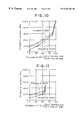
- FIG. 10 is a view for showing a relation between a plug life of a plug of a plug mill machine (as compared with that of the prior art) and a bending strength of ceramics.
- FIG. 11 is a view for showing a relation between a plug life of a plug of a reel machine (as compared with that of the prior art) and a bending strength of ceramics.
- a plug 1 of a piercing machine is constructed such that each of segments of the plug is defined as an extremity end section 10 (a length: 3 mm, R 10 mm), a work section 11 (a length: 40 mm), a reeling section 12 (a length: 50 mm, a slant angle 3.25°) and a parallel section 13 (a length: 15 mm, ⁇ 42 mm) and each of these sections is discriminated by its action.
- extremity end section 10 a length: 3 mm, R 10 mm
- a work section 11 a length: 40 mm
- a reeling section 12 a length: 50 mm, a slant angle 3.25°
- a parallel section 13 a length: 15 mm, ⁇ 42 mm
- the extremity end section 10 is a part where a hole is punched at the central part of the billet
- the work section 11 is a part where a pipe wall thickness is reduced with a clearance being left against the roll
- the reeling section 12 is a part where a pipe wall thickness is finished with a clearance being against the roll
- the parallel section 13 is a part where a removal of the hollow member from the plug is made smooth.
- the plug 1 of the piercing machine a length of the extremity section 5 mm, R 10 mm, a length of the work section 30 mm, a length of the reeling section 45 mm, a slant angle 3.75°, a length of parallel section 15 mm, ⁇ 48 mm
- the plug 3 of a plug mill in FIG. 3 (a forward or rearward symmetrical shape, the extremity end section 2 mm, R 5 mm, a length of the work section 5 mm, a length of the reeling section 10 mm, a slant angle 10°, a length of parallel section 20 mm, ⁇ 49 mm)
- the mandrel bar 5 in FIG. 5 forms a rod-like member in which the plug and the plug bar supporting the plug are integrally assembled (a length of the extremity end section 3 mm, R 26.5 mm, a length of the work section 3000 mm, ⁇ 53 mm).
- a pipe wall thickness at a part of the mandrel bar of which outer appearance shape is approximately parallel is reduced, so that the parallel part of its outer appearance of the mandrel bar of the present invention is called as a work section.
- the plug corresponding to the present invention, four kinds of ceramics powder of SiC, ZnO 2 , Al 2 O 3 , Si 3 N 4 were used as the aforesaid ceramics. Then, the plug was manufactured in such a way that each of these ceramics powder was molded individually, baked, and then finished into the shapes shown in FIGS. 1 and 2 to 5 by a grinding operation.
- the molding was performed such that the ceramics powder was mixed with sintered member such as glass, finished into the shape of plug (rough shape in view of shrinkage caused by baking), the baking was carried out in baking and solidifying within a furnace (an atmospheric furnace or an atmospheric control or isohydraulic furnace or the like) and the grinding was performed with a diamond grinding stone to make a grinding finish.
- the plug of the present invention may be kept at a state in which it is not ground finished, but it is left in its baked condition in view of rolling condition.
- the billet of SUS304 with ⁇ 50 mm heated up to 1250° C. was rolled by a model piercing machine into a hollow member with an outer diameter of ⁇ 55 mm. After this operation, this hollow member was cooled with air and passed in sequence through the following two steps of ⁇ circle around (1) ⁇ and ⁇ circle around (2) ⁇ to make a shell member. Then, a life of the plug and the bar used in each of the model mills was evaluated.
- the plug of the piercing machine and the plug of the elongating machine are made of casted steel of 0.3 wt. % C—0.3 wt. % Cr—1 wt. % Ni and oxidation scale is generated at the surface by a heat treatment.
- the mandrel bar corresponds to the JIS standards (SKT6), this is also processed by a heat treatment to form an oxidation scale at the surface, thereafter lubricant of graphite system is coated on it.
- the plug of the plug mill is made of casted steel with 1.5 wt. % C—18 wt. % Cr—1.5 wt. % Ni, an oxidation scale is produced at the surface by a heat treatment and lubricant of graphite system is coated on it.
- the plug of reeling machine is made of casted iron of 3 wt. % C—0.6 wt. % Cr—0.4 wt. % Ni system and this is left without being heat treated while it is machined.
- Table 1 indicates a life of each of the plug and the bar.
- the life is evaluated in reference to the number (called as a durable number) of rolled members (billet, hollow member or shell) which are rolled until one plug or bar is worn out under its continuous application in use and the worn-out member is replaced with another member.
- the present invention as the present third and fifth inventions, required at first that the entire plug and bar are made of ceramics. Accordingly, it can be expected that, if the actual plug and bar for use in rolling the seamless steel pipe are manufactured in such a way as described above, the life of these members can be reached up to such a level as one which could be attained.
- the plug having the outer appearance shape shown in FIG. 1 is used as the plug of the elongating machine and the plug of the reel machine, for example, it can be expected that, if each of the members corresponding to the outer appearance shape shown in FIGS. 2 and 3 (the extremity end section 10 and the work section 11 or the reeling section 12 is also added) is replaced with ceramics, the plug has an approximate same life as that of the plug of which entire material is made of ceramics.
- the effect attained by ceramics is assumed to be caused by the fact that deformation at the surface of the plug and melt loss under a high temperature are scarcely found as compared with that of the scaled steel, it may also be applicable that only the surface layer except the inner part of the plug, i.e. the portion processed with ceramics is made of ceramics.
- the inner part of the plug is made of raw material of steel in the same manner as that of the prior art.
- the present inventors applied to a rolling experiment a plug of a piercing machine in which the extremity end section 10 and the work section 11 shown in FIG. 6 ( a ) indicating a plug section are made of ceramics (hatched line), the surface layer section of 6 mm at each of the extremity end section 10 and the work section 11 shown in FIG. 6 ( b ) is made of ceramics (hatched line) and the remaining sections are made of material quality of the prior art product.
- the plug section the present inventors applied to a rolling experiment a plug of a piercing machine in which the extremity end section 10 to the reel section 12 shown in FIG.
- FIG. 7 ( a ) is made of ceramics (hatched line) and only the surface layer of 5 mm at each of the extremity end section 10 to the reel section 12 shown in FIG. 7 ( b ) is made of ceramics (hatched line) and their inner sections as well as other remaining sections are made of material quality of the prior art product. They correspond to the present first and second inventions. Further, the size of the entire plug and the conditions of experiment are the same as those of the aforesaid experiment.
- silica alumina heat-resistant adhesive agent (silica: silicon oxide, alumina: aluminum oxide) was used for connecting the ceramics (hatched line) with the prior art steel member (other than the hatched line) If such a coupling as above is carried out, the different raw materials are hardly peeled off from each other during its use even though the plug or the bar having the complex structure is applied. Further, the present invention is not only limited to this coupling method, but also other coupling methods such as a sintering fit and a screw coupling or the like may be applied.
- the present first to second and fourth inventions are made on the basis of this technical concept, if they are applied to the manufacturing of the seamless steel pipe in place of the aforesaid present third and fifth inventions as required, they may provide the similar effects to that of the present third and fifth inventions. That is, in order to attain the plug and the bar having a sufficient longer life than that of the prior art, it is necessary that at least a part ranging from the extremity end of the plug to the work section is formed by ceramics.
- the thickness of the surface layer section is more than 3 mm at the extremity end to the work section and the reel section shows more than 3 mm at its interface with the work section and more than 1 mm at its interface with the parallel section. If not, it is not preferable due to the fact that it may not be durable against a tensile force generated inside (at an interface side with the steel material) the ceramic section under an application of an external load and it may be damaged.
- the present inventors performed the high temperature bending test (JIS R 1601 Three-Point Bending Test) for the ceramics in concurrent with the aforesaid rolling experiment, arranged the results and attained a relation between the ceramic bending strength and the life of the plug. In this case, each of the bending strengths of the ceramics is changed by attaining various states of forming and baking conditions.
- JIS R 1601 Three-Point Bending Test JIS R 1601 Three-Point Bending Test
- the forming conditions are a combination of ceramics crystalline particle shape (from flake to particle, or spherical shape), a grain size and a mixed glass type binder (alumina system, boric acid and others, or their complex state) and as the baking conditions, there are provided a holding temperature (700° to 1600° C.), a cooling speed, atmosphere and pressurizing force or the like.
- FIGS. 8, 9 , 10 and 11 illustrate a relation between a life of each of the plug of a piercing machine, the plug of an elongating machine, the plug of a plug mill and the plug of a reel machine (against the prior art) and a ceramics bending strength in this sequence, respectively.
- the bending strength at 1000° C. for example, is expressed as “a strength at 1000° C.”.
- the present sixth to twelfth inventions have been accomplished on the basis of the result of a high temperature bending test for such ceramics, wherein the ceramics of the plugs in each of the present first to third inventions are restricted under the preferable high temperature bending strength in response to an applied rolling machine, such as a piercing machine, an elongating machine and a reel machine, for example.
- an applied rolling machine such as a piercing machine, an elongating machine and a reel machine, for example.
- the life of the plug of the piercing machine is improved as a bending strength of the applied ceramics is increased. Then, the extension of life is increased at a value more than 200 MPa of a strength at 1200° C. and further the life of more than fifty times of that of the prior art product under a condition of more than 400 MPa of a strength at 1200° C. or more than 200 MPa of a strength at 1300° C. can be attained.
- the applied ceramics is Si 3 N 4 , for example.
- the present sixth invention is the plug of the piercing machine in which a high temperature bending strength of ceramics has a preferable range more than 200 MPa at 1200° C.
- the present seventh invention is the plug of the piercing machine having a strength of more than 400 MPa at 1200° C.
- the present eighth invention is the plug of the piercing machine having a strength of more than 200 MPa at 1300° C.
- the life of the plug of the elongating machine is improved as a bending strength of the applied ceramics is increased.
- the extension of life of it can be increased at a strength of more than 200 MPa at 800° C., and further the life of more than fifty times of that of the prior art product can be attained at a strength of more than 200 MPa at 1000° C.
- the rolling temperature during rolling of the elongating machine does not exceed 1200° C.
- the applied ceramics is ZnO 2 , for example.
- the life of the plug mill is improved as the bending strength of the applied ceramics is increased. Then, the extension of life at a strength of more than 200 MPa at 800° C. is increased and a life more than thirty times of that of the prior art product can be attained at a strength of more than 200 MPa at 1000° C. In general, there occurs no possibility that the rolling temperature at the time of rolling operation of the plug mill exceeds 1200° C.
- the applied ceramics is SiC, for example.
- the present ninth invention defined it more than 200 MPa at 800° C. and as a further preferable range, the present tenth invention defined it more than 200 MPa at 1000 to 1200° C.
- the life of the reel machine is improved as the bending strength of the applied ceramics is increased. Then, the extension of life at a strength of more than 200 MPa at 800° C. is increased and a life more than hundred times of that of the prior art product can be attained at a strength of more than 200 MPa at 1000° C. In general, there occurs no possibility that the rolling temperature at the time of rolling operation of the reel machine exceeds 1000° C.
- the applied ceramics is Al 2 O 3 , for example.
- the present eleventh invention defined it more than 200 MPa at 800° C. and as a further range which is more suitable for actual case, the present twelfth invention defined it more than 200 MPa at 800 to 1200° C.
- the present thirteenth invention relates to a method in which the plug of any of the present first to third, and sixth to eighth inventions is applied to the piercing machine so as to make a hole at the billet and then the billet is rolled, the processings at the subsequent to the hollow member may be carried out in any method of rolling operation. That is, it may also be applicable that all the plugs or bars in the present invention are used in the rolling machine subsequent to the elongating machine and the well-known prior art product may be used.
- the present fourteenth invention is operated such that the plugs of the present first to third and ninth to tenth inventions are applied to the elongating machine so as to roll the hollow member, wherein the punching stage at the piercing machine in the prior stage or the processing in subsequent stages is not restricted in particular.
- the present fifteenth invention is operated such that the plugs of any ones of the present first to third and eleventh to twelfth inventions are applied to the reel machine so as to roll the hollow member, wherein the present sixteenth invention is additionally operated such that the plugs of any one of the present first to third and ninth to tenth inventions are installed at the plug mill so as to roll the hollow member and the present seventeenth invention is operated such that the bar of the present fourth or fifth invention is installed at the mandrel mill so as to roll the hollow member.
- all the inventions do not restrict either the plug or the bar in particular to the product of the present invention during the processing other than that of the target rolling machine.
- the seamless steel pipe is manufactured under application of either the plug or the bar of the present invention having a remarkable longer life than that of the prior art product, so that there may be generated various useful effects in industry such as a cost reduction caused by a decreased unit of tool, and an improved productivity caused by reduction of frequent replacement of the tool or the like.
- Each of ceramic powders of four kinds of ceramics such as SiC, ZnO 2 , Al 2 O 3 , and Si 3 N 4 was press formed individually and baked to adjust a strength at 1000° C. to the aforesaid values of 1000 Mpa, 1000 MPa, 450 MPa, and 1000 MPa, respectively. Then, each of the raw materials was finished into a product in which the material shows an outer appearance shape of each of the entire ceramic plugs shown in FIGS. 1 to 5 with an enlarged size of expanded rate, another product partially made of ceramics, a plug and a bar in which a part of the surface layer except the inner side is made of ceramics and then they were used in the following examples 1 and 2.
- Billet ( ⁇ 175 mm) made of high alloy steel having a higher deformation resistance than that of 9 wt. % Cr steel was rolled in sequence by the plugs shown in FIGS. 1 to 5 in the piercing machine and the mandrel mill with its expansion rate being three times so as to manufacture the seamless steel pipe.
- the mandrel bars were used at both piercing machine and mandrel mill in which a surface layer depth of 35 mm down to the plug of the piercing machine and the work section (the outer appearance parallel section) entirely made of ceramics up to the parallel section of the present invention was made of ceramics.
- Billet ( ⁇ 350 mm) made of high alloy steel having a higher deformation resistance than that of 16 wt. % Cr steel was rolled in sequence by the plugs shown in FIGS. 1 to 5 in the piercing machine, an elongating machine, a plug mill and a reel machine with its expansion rate being set to 6.5 so as to manufacture the seamless steel pipe.
- the plugs of the present invention were used at all the aforesaid rolling machines.
- the entire piercing machine used the plug in which the entire assembly up to the reel section was made of ceramics
- the elongating machine used the plug in which the surface layer depth down to the work section of 80 mm was made of ceramics
- the plug mill used the plug in which the entire surface layer depth of 70 mm was made of ceramics
- the reel machine used the plug in which the surface layer depth of 25 mm down to the reel section was made of ceramics.
Landscapes
- Engineering & Computer Science (AREA)
- Mechanical Engineering (AREA)
- Reduction Rolling/Reduction Stand/Operation Of Reduction Machine (AREA)
Applications Claiming Priority (3)
| Application Number | Priority Date | Filing Date | Title |
|---|---|---|---|
| JP8349228A JPH10180315A (ja) | 1996-12-27 | 1996-12-27 | 継目無鋼管圧延用プラグおよび継目無鋼管の製造方法 |
| JP8-349228 | 1996-12-27 | ||
| PCT/JP1997/004741 WO1998029204A1 (fr) | 1996-12-27 | 1997-12-22 | Tampon filete et mandrin pour laminage de tube metallique sans soudure et procede de fabrication d'un tube metallique sans soudure |
Publications (1)
| Publication Number | Publication Date |
|---|---|
| US6202463B1 true US6202463B1 (en) | 2001-03-20 |
Family
ID=18402353
Family Applications (1)
| Application Number | Title | Priority Date | Filing Date |
|---|---|---|---|
| US09/214,935 Expired - Fee Related US6202463B1 (en) | 1996-12-27 | 1997-12-22 | Plug and mandrel bar for seamless steel pipe rolling operation for manufacturing seamless steel pipe |
Country Status (8)
| Country | Link |
|---|---|
| US (1) | US6202463B1 (pt) |
| EP (1) | EP1010477B1 (pt) |
| JP (1) | JPH10180315A (pt) |
| KR (1) | KR100403061B1 (pt) |
| CN (1) | CN1191889C (pt) |
| BR (1) | BR9711434A (pt) |
| DE (1) | DE69729488T2 (pt) |
| WO (1) | WO1998029204A1 (pt) |
Cited By (9)
| Publication number | Priority date | Publication date | Assignee | Title |
|---|---|---|---|---|
| US20050211571A1 (en) * | 2002-06-28 | 2005-09-29 | Jurgen Schulein | Electrochemical detection method and device |
| US20050210944A1 (en) * | 2002-12-12 | 2005-09-29 | Hirotsugu Nakaike | Making method for seamless metallic tube |
| US20070157691A1 (en) * | 2004-06-18 | 2007-07-12 | Sumio Iida | Process for producing seamless steel pipe |
| US7383710B2 (en) * | 2004-03-11 | 2008-06-10 | Sumitomo Metal Industries, Ltd. | Seamless tube piercing/rolling apparatus, and seamless tube producing therewith |
| CN102284777A (zh) * | 2010-06-17 | 2011-12-21 | 上海宝钢设备检修有限公司 | 无缝钢管穿孔机顶头表面堆焊强化的方法 |
| CN103658185A (zh) * | 2013-11-28 | 2014-03-26 | 苏州踵力重型机械有限公司 | 无缝钢管高效穿孔顶头 |
| DE102014000461A1 (de) * | 2014-01-14 | 2015-07-16 | Hua Guo | Innenwerkzeug für die Herstellung nahtloser Stahlrohre |
| US20150258591A1 (en) * | 2013-01-11 | 2015-09-17 | Nippon Steel & Sumitomo Metal Corporation | Plug for hot tube-making |
| RU2584620C1 (ru) * | 2012-07-20 | 2016-05-20 | Ниппон Стил Энд Сумитомо Метал Корпорейшн | Оправка прошивного стана |
Families Citing this family (10)
| Publication number | Priority date | Publication date | Assignee | Title |
|---|---|---|---|---|
| CN1086965C (zh) * | 1999-10-19 | 2002-07-03 | 赵士英 | 无缝钢管轧制用芯棒生产的新工艺技术 |
| DE102005044777A1 (de) * | 2005-09-20 | 2007-03-29 | Sms Meer Gmbh | Verfahren und Walzwerk zur Herstellung eines nahtlosen Rohres |
| DE102007037736B4 (de) * | 2007-08-09 | 2012-11-15 | Kocks Technik Gmbh & Co. Kg | Dorn oder Dornstange für ein Rohrherstellungsverfahren und Verwendung solch eines Dorns oder solch einer Dornstange |
| EP2198984B1 (en) | 2007-11-01 | 2016-12-14 | Nippon Steel & Sumitomo Metal Corporation | Piercing plug, method for regenerating piercing plug, and regeneration facility line for piercing plug |
| EP2837434B1 (en) * | 2012-04-11 | 2018-01-17 | Nippon Steel & Sumitomo Metal Corporation | Plug used in piercing machine and plug regeneration method |
| JP5273272B1 (ja) * | 2012-04-25 | 2013-08-28 | 新日鐵住金株式会社 | 穿孔圧延用プラグの製造方法 |
| JP5445724B1 (ja) | 2012-08-28 | 2014-03-19 | 新日鐵住金株式会社 | 穿孔プラグ及び穿孔プラグの製造方法 |
| CN106336238B (zh) * | 2016-08-30 | 2019-06-14 | 江苏南山冶金机械制造有限公司 | 一种高强度耐高温防裂穿孔机顶头 |
| CN111875384A (zh) * | 2020-08-11 | 2020-11-03 | 中钢集团洛阳耐火材料研究院有限公司 | 一种无缝钢管热穿孔用碳化硅顶头的制备方法 |
| CN112077306B (zh) * | 2020-08-20 | 2021-11-19 | 华中科技大学 | 激光选区熔覆强化无缝钢管穿孔顶头的方法及得到的顶头 |
Citations (16)
| Publication number | Priority date | Publication date | Assignee | Title |
|---|---|---|---|---|
| JPS51133167A (en) | 1975-05-15 | 1976-11-18 | Nippon Steel Corp | Method of producing seamless tube |
| JPS6030964A (ja) | 1983-07-29 | 1985-02-16 | 三菱電機株式会社 | 冷凍装置 |
| JPS60137511A (ja) | 1983-12-27 | 1985-07-22 | Nippon Kokan Kk <Nkk> | 継目無管製造用プラグ |
| JPS60159156A (ja) | 1984-01-27 | 1985-08-20 | Shinhoukoku Seitetsu Kk | 継目無し鋼管の穿孔および拡管用芯金合金 |
| JPS60208458A (ja) | 1984-03-31 | 1985-10-21 | Shinhoukoku Seitetsu Kk | 継目なし鋼管の穿孔および拡管用芯金合金 |
| JPS62170479A (ja) | 1986-01-23 | 1987-07-27 | Sumitomo Metal Ind Ltd | 熱間工具 |
| JPS62238011A (ja) | 1986-04-07 | 1987-10-19 | Nippon Steel Corp | 鋼管圧延機用芯金 |
| JPS62244505A (ja) | 1986-04-17 | 1987-10-24 | Nippon Kokan Kk <Nkk> | 継目無管製造用プラグ |
| JPS63203205A (ja) | 1987-02-17 | 1988-08-23 | Sumitomo Metal Ind Ltd | 穿孔機用プラグ |
| JPH01180712A (ja) | 1987-12-28 | 1989-07-18 | Sumitomo Metal Ind Ltd | 金属穿孔具 |
| JPH02156037A (ja) | 1988-12-09 | 1990-06-15 | Nippon Steel Corp | 耐熱穿孔プラグ |
| JPH02268909A (ja) | 1989-04-12 | 1990-11-02 | Nkk Corp | 継目無し鋼管製造用プラグ |
| US5031434A (en) * | 1989-02-28 | 1991-07-16 | Nkk Corporation | Plug for manufacturing seamless steel pipe |
| JPH03165904A (ja) | 1989-11-22 | 1991-07-17 | Nippon Steel Corp | 穿孔用プラグ |
| JPH0585242A (ja) | 1991-09-30 | 1993-04-06 | Nissan Motor Co Ltd | シート支持装置 |
| JPH05138213A (ja) | 1991-11-21 | 1993-06-01 | Kawasaki Steel Corp | 継目無鋼管穿孔プラグの潤滑方法 |
Family Cites Families (1)
| Publication number | Priority date | Publication date | Assignee | Title |
|---|---|---|---|---|
| JPS6030964Y2 (ja) * | 1981-02-25 | 1985-09-17 | 新日本製鐵株式会社 | 穿孔圧延用プラグ |
-
1996
- 1996-12-27 JP JP8349228A patent/JPH10180315A/ja active Pending
-
1997
- 1997-12-22 KR KR10-1999-7002096A patent/KR100403061B1/ko not_active Expired - Fee Related
- 1997-12-22 US US09/214,935 patent/US6202463B1/en not_active Expired - Fee Related
- 1997-12-22 BR BR9711434A patent/BR9711434A/pt not_active IP Right Cessation
- 1997-12-22 CN CNB971978573A patent/CN1191889C/zh not_active Expired - Fee Related
- 1997-12-22 EP EP97949197A patent/EP1010477B1/en not_active Expired - Lifetime
- 1997-12-22 WO PCT/JP1997/004741 patent/WO1998029204A1/ja not_active Ceased
- 1997-12-22 DE DE69729488T patent/DE69729488T2/de not_active Expired - Fee Related
Patent Citations (16)
| Publication number | Priority date | Publication date | Assignee | Title |
|---|---|---|---|---|
| JPS51133167A (en) | 1975-05-15 | 1976-11-18 | Nippon Steel Corp | Method of producing seamless tube |
| JPS6030964A (ja) | 1983-07-29 | 1985-02-16 | 三菱電機株式会社 | 冷凍装置 |
| JPS60137511A (ja) | 1983-12-27 | 1985-07-22 | Nippon Kokan Kk <Nkk> | 継目無管製造用プラグ |
| JPS60159156A (ja) | 1984-01-27 | 1985-08-20 | Shinhoukoku Seitetsu Kk | 継目無し鋼管の穿孔および拡管用芯金合金 |
| JPS60208458A (ja) | 1984-03-31 | 1985-10-21 | Shinhoukoku Seitetsu Kk | 継目なし鋼管の穿孔および拡管用芯金合金 |
| JPS62170479A (ja) | 1986-01-23 | 1987-07-27 | Sumitomo Metal Ind Ltd | 熱間工具 |
| JPS62238011A (ja) | 1986-04-07 | 1987-10-19 | Nippon Steel Corp | 鋼管圧延機用芯金 |
| JPS62244505A (ja) | 1986-04-17 | 1987-10-24 | Nippon Kokan Kk <Nkk> | 継目無管製造用プラグ |
| JPS63203205A (ja) | 1987-02-17 | 1988-08-23 | Sumitomo Metal Ind Ltd | 穿孔機用プラグ |
| JPH01180712A (ja) | 1987-12-28 | 1989-07-18 | Sumitomo Metal Ind Ltd | 金属穿孔具 |
| JPH02156037A (ja) | 1988-12-09 | 1990-06-15 | Nippon Steel Corp | 耐熱穿孔プラグ |
| US5031434A (en) * | 1989-02-28 | 1991-07-16 | Nkk Corporation | Plug for manufacturing seamless steel pipe |
| JPH02268909A (ja) | 1989-04-12 | 1990-11-02 | Nkk Corp | 継目無し鋼管製造用プラグ |
| JPH03165904A (ja) | 1989-11-22 | 1991-07-17 | Nippon Steel Corp | 穿孔用プラグ |
| JPH0585242A (ja) | 1991-09-30 | 1993-04-06 | Nissan Motor Co Ltd | シート支持装置 |
| JPH05138213A (ja) | 1991-11-21 | 1993-06-01 | Kawasaki Steel Corp | 継目無鋼管穿孔プラグの潤滑方法 |
Cited By (17)
| Publication number | Priority date | Publication date | Assignee | Title |
|---|---|---|---|---|
| US20050211571A1 (en) * | 2002-06-28 | 2005-09-29 | Jurgen Schulein | Electrochemical detection method and device |
| CN100404151C (zh) * | 2002-12-12 | 2008-07-23 | 住友金属工业株式会社 | 无缝金属管的制造方法 |
| US20050210944A1 (en) * | 2002-12-12 | 2005-09-29 | Hirotsugu Nakaike | Making method for seamless metallic tube |
| US6988387B2 (en) * | 2002-12-12 | 2006-01-24 | Sumitomo Metal Industries, Ltd. | Making method for seamless metallic tube |
| US7506526B2 (en) | 2004-03-11 | 2009-03-24 | Sumitomo Metal Industries, Ltd. | Seamless tube piercing/rolling plug, and seamless tube producing method using same |
| US7383710B2 (en) * | 2004-03-11 | 2008-06-10 | Sumitomo Metal Industries, Ltd. | Seamless tube piercing/rolling apparatus, and seamless tube producing therewith |
| US20080134742A1 (en) * | 2004-03-11 | 2008-06-12 | Tomio Yamakawa | Seamless tube piercing/rolling plug, and seamless tube producing method using same |
| US7308812B2 (en) * | 2004-06-18 | 2007-12-18 | Sumitomo Metal Industries, Ltd. | Process for producing seamless steel pipe |
| US20070157691A1 (en) * | 2004-06-18 | 2007-07-12 | Sumio Iida | Process for producing seamless steel pipe |
| CN102284777A (zh) * | 2010-06-17 | 2011-12-21 | 上海宝钢设备检修有限公司 | 无缝钢管穿孔机顶头表面堆焊强化的方法 |
| RU2584620C1 (ru) * | 2012-07-20 | 2016-05-20 | Ниппон Стил Энд Сумитомо Метал Корпорейшн | Оправка прошивного стана |
| US10150147B2 (en) | 2012-07-20 | 2018-12-11 | Nippon Steel & Sumitomo Metal Corporation | Piercing plug |
| US20150258591A1 (en) * | 2013-01-11 | 2015-09-17 | Nippon Steel & Sumitomo Metal Corporation | Plug for hot tube-making |
| US9352370B2 (en) * | 2013-01-11 | 2016-05-31 | Nippon Steel & Sumitomo Metal Corporation | Plug for hot tube-making |
| CN103658185A (zh) * | 2013-11-28 | 2014-03-26 | 苏州踵力重型机械有限公司 | 无缝钢管高效穿孔顶头 |
| DE102014000461A1 (de) * | 2014-01-14 | 2015-07-16 | Hua Guo | Innenwerkzeug für die Herstellung nahtloser Stahlrohre |
| DE102014000461B4 (de) * | 2014-01-14 | 2017-01-05 | Hua Guo | Innenwerkzeug für die Herstellung nahtloser Stahlrohre |
Also Published As
| Publication number | Publication date |
|---|---|
| DE69729488T2 (de) | 2005-06-09 |
| JPH10180315A (ja) | 1998-07-07 |
| EP1010477A4 (en) | 2002-06-05 |
| CN1230138A (zh) | 1999-09-29 |
| DE69729488D1 (de) | 2004-07-15 |
| BR9711434A (pt) | 1999-08-24 |
| KR20000036084A (ko) | 2000-06-26 |
| KR100403061B1 (ko) | 2003-10-24 |
| WO1998029204A1 (fr) | 1998-07-09 |
| EP1010477A1 (en) | 2000-06-21 |
| CN1191889C (zh) | 2005-03-09 |
| EP1010477B1 (en) | 2004-06-09 |
Similar Documents
| Publication | Publication Date | Title |
|---|---|---|
| US6202463B1 (en) | Plug and mandrel bar for seamless steel pipe rolling operation for manufacturing seamless steel pipe | |
| US5252130A (en) | Apparatus which comes in contact with molten metal and composite member and sliding structure for use in the same | |
| KR102118543B1 (ko) | 브리켓 롤 및 그 제조방법 | |
| KR20120041241A (ko) | 얇은 열간 압연 스트립 제조 장치 및 그 방법 | |
| KR100338572B1 (ko) | 박냉연강대압연용복합롤및그제조방법 | |
| JPH07185635A (ja) | 圧延ライン用セラミックス製ガイド | |
| KR930007138B1 (ko) | 오스테나이트계 스테인레스강의 냉간압연 스트립 및 시이트의 제조방법 | |
| US5406825A (en) | Forging die | |
| EP1283079A1 (en) | Composite roll of cemented carbide, and steel hot-rolling method using the same | |
| CN106424501A (zh) | 基于包套的难变形材料多向锻压加工方法 | |
| JP2006181628A (ja) | 厚鋼板の圧延方法および厚鋼板の製造方法 | |
| JP3512720B2 (ja) | 圧延設備用表層改質ロール及び表層改質冷間圧延ロール並びに圧延設備用ロールの表面改質方法 | |
| JP2008246562A (ja) | 熱間圧延方法 | |
| EP2060334A1 (en) | METHOD OF USING Cr-PLATED MANDREL BAR FOR HOT ROLLING | |
| JP2004195518A (ja) | 連続熱間圧延方法 | |
| JP3172483B2 (ja) | 金属帯板圧延用複合ロールとその製造方法 | |
| JP2002224703A (ja) | 形鋼の圧延方法 | |
| JP2004195515A (ja) | ステンレス鋼の熱間圧延方法 | |
| JP2002224715A (ja) | 厚鋼板の圧延方法 | |
| JP2006122976A (ja) | 熱間圧延方法及びそれを用いた熱延金属帯の製造方法 | |
| JPH08206708A (ja) | 傾斜圧延用プラグ及びその製造方法 | |
| JPH0563252B2 (pt) | ||
| JP2002224717A (ja) | 鋼の熱間圧延方法 | |
| JP2007160338A (ja) | 熱間加工用工具および継目無鋼管の製造方法 | |
| JP2002102908A (ja) | 金属帯の冷間圧延方法 |
Legal Events
| Date | Code | Title | Description |
|---|---|---|---|
| AS | Assignment |
Owner name: KAWASAKI STEEL CORPORATION, JAPAN Free format text: ASSIGNMENT OF ASSIGNORS INTEREST;ASSIGNORS:YORIFUJI, AKIRA;TOYOOKA, TAKAAKI;KANAYAMA, TARO;REEL/FRAME:009853/0951 Effective date: 19990113 |
|
| CC | Certificate of correction | ||
| FPAY | Fee payment |
Year of fee payment: 4 |
|
| REMI | Maintenance fee reminder mailed | ||
| LAPS | Lapse for failure to pay maintenance fees | ||
| STCH | Information on status: patent discontinuation |
Free format text: PATENT EXPIRED DUE TO NONPAYMENT OF MAINTENANCE FEES UNDER 37 CFR 1.362 |
|
| FP | Lapsed due to failure to pay maintenance fee |
Effective date: 20090320 |