US6202863B1 - Sucker rod cradle apparatus - Google Patents
Sucker rod cradle apparatus Download PDFInfo
- Publication number
- US6202863B1 US6202863B1 US09/038,580 US3858098A US6202863B1 US 6202863 B1 US6202863 B1 US 6202863B1 US 3858098 A US3858098 A US 3858098A US 6202863 B1 US6202863 B1 US 6202863B1
- Authority
- US
- United States
- Prior art keywords
- rods
- cradle
- base frame
- sucker
- arms
- Prior art date
- Legal status (The legal status is an assumption and is not a legal conclusion. Google has not performed a legal analysis and makes no representation as to the accuracy of the status listed.)
- Expired - Fee Related
Links
- 125000006850 spacer group Chemical group 0.000 claims abstract description 55
- 239000000356 contaminant Substances 0.000 claims abstract description 5
- 230000003014 reinforcing effect Effects 0.000 claims description 7
- 238000000034 method Methods 0.000 description 14
- 229910000831 Steel Inorganic materials 0.000 description 3
- 239000000463 material Substances 0.000 description 3
- 239000002184 metal Substances 0.000 description 3
- 239000003129 oil well Substances 0.000 description 3
- 239000010959 steel Substances 0.000 description 3
- 238000005452 bending Methods 0.000 description 2
- 238000011109 contamination Methods 0.000 description 2
- 230000001419 dependent effect Effects 0.000 description 2
- 230000000994 depressogenic effect Effects 0.000 description 1
- 239000007788 liquid Substances 0.000 description 1
- 238000004519 manufacturing process Methods 0.000 description 1
- 229910001092 metal group alloy Inorganic materials 0.000 description 1
- 238000012986 modification Methods 0.000 description 1
- 230000004048 modification Effects 0.000 description 1
- 239000003208 petroleum Substances 0.000 description 1
- 230000001012 protector Effects 0.000 description 1
- 238000005086 pumping Methods 0.000 description 1
- 238000011084 recovery Methods 0.000 description 1
Images




Classifications
-
- E—FIXED CONSTRUCTIONS
- E21—EARTH OR ROCK DRILLING; MINING
- E21B—EARTH OR ROCK DRILLING; OBTAINING OIL, GAS, WATER, SOLUBLE OR MELTABLE MATERIALS OR A SLURRY OF MINERALS FROM WELLS
- E21B19/00—Handling rods, casings, tubes or the like outside the borehole, e.g. in the derrick; Apparatus for feeding the rods or cables
- E21B19/14—Racks, ramps, troughs or bins, for holding the lengths of rod singly or connected; Handling between storage place and borehole
- E21B19/15—Racking of rods in horizontal position; Handling between horizontal and vertical position
-
- B—PERFORMING OPERATIONS; TRANSPORTING
- B65—CONVEYING; PACKING; STORING; HANDLING THIN OR FILAMENTARY MATERIAL
- B65D—CONTAINERS FOR STORAGE OR TRANSPORT OF ARTICLES OR MATERIALS, e.g. BAGS, BARRELS, BOTTLES, BOXES, CANS, CARTONS, CRATES, DRUMS, JARS, TANKS, HOPPERS, FORWARDING CONTAINERS; ACCESSORIES, CLOSURES, OR FITTINGS THEREFOR; PACKAGING ELEMENTS; PACKAGES
- B65D88/00—Large containers
- B65D88/02—Large containers rigid
- B65D88/12—Large containers rigid specially adapted for transport
- B65D88/122—Large containers rigid specially adapted for transport with access from above
- B65D88/123—Large containers rigid specially adapted for transport with access from above open top
-
- B—PERFORMING OPERATIONS; TRANSPORTING
- B65—CONVEYING; PACKING; STORING; HANDLING THIN OR FILAMENTARY MATERIAL
- B65D—CONTAINERS FOR STORAGE OR TRANSPORT OF ARTICLES OR MATERIALS, e.g. BAGS, BARRELS, BOTTLES, BOXES, CANS, CARTONS, CRATES, DRUMS, JARS, TANKS, HOPPERS, FORWARDING CONTAINERS; ACCESSORIES, CLOSURES, OR FITTINGS THEREFOR; PACKAGING ELEMENTS; PACKAGES
- B65D88/00—Large containers
- B65D88/02—Large containers rigid
- B65D88/12—Large containers rigid specially adapted for transport
- B65D88/129—Transporter frames for containers
Definitions
- This invention relates in general to sucker rods used in oil well recovery and more particularly to a sucker rod cradle apparatus for handling, storing and transporting sucker rods.
- Sucker rods are typically used in oil well pumping operations to stroke or drive the pump located near the bottom of the well bore and subsequently facilitate the withdrawal of oil from the production zone or reservoir.
- Several such rods must be coupled together to form a sucker rod string and therefore, dependent on the depth, large numbers of such rods must be handled, stored and transported to various oil well sites on a regular basis.
- a common method for the handling, storage and transporting of sucker rods comprises layering and stacking the sucker rods between wooden boards approximately 2.5′′ wide by 30′′ in length with each board having grooves to space and hold a capacity of 15 rods. The boards are spaced at five standardized increments along the length of a sucker rod which is typically 25 feet.
- Subsequent layers or tiers of 15 rods each are then added by using another five boards along the length of the rod directly above the lower five boards.
- a typical bundle of 60 sucker rods comprising four layers or tiers of 15 rods each is produced in this manner.
- the final step is the addition of a fifth top board to each column of boards in such a manner that the 15 grooves fit into the top tier of rods.
- the five columns of five boards each are then strapped together using steel banding.
- a novel apparatus has been developed for the handling, storage and transporting of sucker rods.
- the apparatus overcomes the disadvantages of the previously used methods for bundling, handling, storing and transporting sucker rods.
- the present apparatus significantly enhances the protection of all sucker rods placed within from damage and also provides a level of contamination containment far greater than is currently being practised by the oil industry in general when removing used rods from a well.
- the apparatus of the present invention allows for the use of steel banding to make individual bundles of rods, it is not necessary to band the rods.
- the apparatus makes it possible to store, add or remove and transport sucker rods without the need to unbundle or rebundle any rods. This significantly reduces the amount of labour and related costs currently required to handle the rods.
- a sucker rod cradle for the storage, handling and transportation of rods, the apparatus comprises in combination:
- a base frame having a pocket means for engagement with corresponding fork means of a forklift;
- cradle arms spaced at intervals along the length of the base frame, the cradle arms extending substantially perpendicular to the base frame to contain rods stacked therein, and
- the cradle arms having means for receiving the ends of corresponding spacer means for spacing rods.
- FIG. 1 is a perspective view showing a sucker rod cradle apparatus in accordance with the preferred embodiment of the present invention
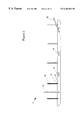
- FIG. 2 is a side elevational view of the apparatus in accordance with the preferred embodiment of the present invention.
- FIG. 3 is an vertical sectional view of the cradle arms, base frame and drip pan profile in accordance with the preferred embodiment of the present invention
- FIGS. 4A and B are horizontal and vertical sectional views of the lifting bars in accordance with a preferred embodiment of the present invention.
- FIG. 6 is a horizontal sectional view of a cradle arm in accordance with the preferred embodiment of the present invention.
- FIG. 7 is a perspective view showing a sucker rod cradle apparatus in accordance with the second embodiment of the invention.
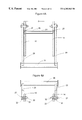
- FIG. 8A is a side elevational view and derail of the apparatus in accordance with The second embodiment of the invention.
- FIG. 8B is a detail side view of the fork lift pockets
- FIG. 9 is a vertical sectional view of the cradle arms and base frame in accordance with the second embodiment of the invention.
- FIG. 10A is a horizontal sectional view and detail of the loading apparatus in accordance with the second embodiment of the invention.
- FIG. 10B is a side elevational view of a bracket as used in the apparatus of FIG. 10 A.
- FIG. 11 is a vertical sectional view of the interconnecting beam and the cradle arm base pocket in accordance with the second embodiment of the invention.
- FIG. 12 is a horizontal sectional view of a cradle arm in accordance with the second embodiment of the invention.
- FIG. 13 is a side elevational view of the sucker rod spacer in accordance with both the first and second embodiments of the invention.
- FIG. 14 is a horizontal sectional view of the bundle spacer in accordance with both the present and second embodiments of the invention.
- FIG. 15 is a partial perspective view of rods stored in the cradle.
- the sucker rod cradle apparatus 10 is shown in FIGS. 1 and 2.
- the apparatus comprises a base frame which in accordance with this particular embodiment has spaced apart parallel beams 12 and 14 , interconnected by a plurality of cross members 24 .
- the base frame may be constructed in other ways to provide a base or platform on which the rods are stacked.
- the base frame may be slightly longer than the length of the sucker rods, this being approximately 25 feet.
- the base frame, in particular, the spaced apart beams 12 and 14 preferably have aligned pairs of pockets 16 and 18 within inverted channels 17 and 19 . In this view the drip pans 15 are removed except for the one covering channel 19 .
- These pockets 16 and 18 are designed to engage with corresponding forks on a fork lift and provide a quick and easy method of handling and moving the cradle.
- the apparatus has a plurality of upright cradle arms 20 spaced at substantially regular intervals along the length of and connected to the base frame.
- the cradle arms 20 extend perpendicular from the beams 12 and 14 preferably at the cross members 24 , and are designed to contain the vertical columns of sucker rods spacers 30 and optional bundle spacers 28 of FIGS. 13 and 14.
- the cradle arms 20 have opposing channels 22 for receiving the ends of corresponding sucker rod spacers 30 and optional bundle spacers 28 .
- the channels allow one to slide the spacers down through the opposing members and capture the spacer ends as rods are placed thereon. This arrangement is described in more detail with regard to FIG. 15 .
- the vertical cradle arms 20 have a horizontal reinforcing base member 24 , a plurality of vertically opposing channel members 22 , and a plurality of horizontally opposing channel members 25 on top of which and within which the first rod spacer and subsequently the first layer or tier of sucker rods is placed.
- the horizontal base members 24 are located between and preferably welded to beams 12 and 14 .
- the horizontally opposing channel members 25 are located at the base of, between and adjacent to the vertical cradle arms 20 and directly below the vertically opposing channels 22 forming the base pocket.
- a drip pan 15 is located in a recessed position between and adjacent beams 12 and 14 and within each segmented length created by the plurality of horizontal base members 24 .
- the pan has a plugged drain hole 13 .
- the drip pan 15 is recessed between and along the length of beams 12 and 14 and acts to help contain any contaminating material that may drip from used rods when placed in the cradle apparatus.
- contaminating materials include but are not limited to oil and oil derivatives.
- the drip pans 15 can be of various widths and lengths in order to be mounted to the cradle apparatus. It is understood by those skilled in the art, that several drip pans in succession can be positioned between arms 20 along the entire length of the cradle apparatus. Alternatively, a single elongated drip pan can be mounted to the cradle apparatus.
- Each pan has a plugged drain hole 13 shown also in FIG. 3 to permit draining of any liquid contaminants into a suitable reservoir.
- the pivoting U-shaped lifting arms 23 or 26 is mounted through and to the outside of beams 12 and 14 to permit in the alternative, moving the cradle with a crane.
- Each respective lifting bars 23 and 26 can rotate toward the center of the cradle apparatus in order to be easily attached to a crane or picker using relatively short cables or slings.
- the pivoting lifting bars 23 and 26 can also rotate out, over and past the ends of the cradle apparatus in order to facilitate the placement of, or removal of sucker rods and in this position provide additional protection to the ends of the rods.
- Each dependent arm 29 of the U-shaped lifting bars is anchored pivotally to The beams 12 and 14 by pins 27 which pass through independent sleeves 32 and 39 permanently fastened within their respective members. Each pin 27 is then held in place using a nut, bolt and washer assembly 33 .
- the horizontal reinforcing base member 24 has horizontally opposing channel members 25 in which the first sucker rod spacer 30 is placed.
- the horizontally opposing channels 25 can accommodate banding (if desired) by passing the banding beneath the spacer 30 and through the depressed portion or banding gap 27 .
- FIG. 6 illustrates the banding slot 21 located between the cradle arms 20 and the opposing channels 22 .
- the bundle spacer is a substantially elongated rectangular shaped member having ends which fit into the vertically opposing channels 22 on the cradle arms 20 .
- the bundle spacer 28 also includes flat bars 35 welded spaced apart in the base of the spacer so when sucker rod spacer is positioned in the bundle spacer 28 , the flat bars 35 provide a gap through which banding may pass when fabricating a bundle.
- These bundle spacer can be used to separate an appropriate number of tiers of sucker rods if desired. The number of tiers of rods being typically twelve to sixteen as capacity for each cradle.
- FIG. 13 shows a sucker rod spacer 30 which is also elongated and rectangular and designed to fit within the vertically opposing channels 22 of the cradle arms 20 and as well in the base of the bundle spacer 28 .
- the sucker rod spacer 30 has a plurality of grooves 32 along one longitudinal surface in which the sucker rods are set resulting in even placement and spacing so that the sucker rods are independently spaced and therefore do not touch each other. In this manner they are not damaged.
- the sucker rod spacer has 15 grooves in which an equivalent number of sucker rods can be placed.
- the sucker rod spacer can be made with larger diameter or smaller diameter grooves to accommodate a fewer or a greater number of rods per tier.
- FIG. 7 A second embodiment of the invention is shown in FIG. 7 .
- the base frame has beams made from interconnected spaced apart members 34 and 36 as shown again in FIG. 8 A.
- the spaced apart members 34 and 36 have aligned pairs of pockets 16 and 18 within inverted channels 17 and 19 as detailed in FIG. 8 B.
- the cradle arms 20 have a pair of spaced apart horizontal reinforcing base members 40 and 42 on top of which the first sucker rod spacer and subsequent first tier of sucker rods is placed. These spaced apart horizontal reinforcing base members are themselves reinforced with a vertical spacer member 46 located substantially at the center of base members 40 and 42 .
- FIG. 10A there are no pivoting arms mounted on the outside of the beams 34 and 36 .
- the ends of the beams 34 and 36 are integral and connected by a bracket 41 as per FIG. 10B to a horizontal bar 38 onto which a lifting apparatus such as a winch line can be attached.
- the bracket 41 has a rounded recess 43 and brace 45 welded to bar 38 to complete the connection.
- the horizontal bar projects beyond the rod ends to protect the ends of the sucker rods stacked within the apparatus.
- the horizontal reinforcing base member 40 is an upright channel member in which the first sucker rod spacer 30 is inserted.
- the upright channel accommodates banding (if desired) by passing the banding beneath the spacer 30 and through opening 41 defined by spaced apart flat bar 49 .
- FIG. 12 illustrates the banding slot 21 contained within the cradle arm 20 of the second embodiment.
- a first layer of sucker rods rest on spacer 30 with grooves 32 facing up are positioned one into each of the five base pockets on top of each cross member 25 and between the vertical channels 22 created by the cradle arms incrementally positioned along the entire length of the beams.
- a fist layer 50 or tier comprising fifteen sucker rods in total is placed into the grooves of each of the five sucker rod spacers 30 .
- Another layer of sucker rod spacers 30 also with the grooves 32 facing up, are then positioned between the channels 22 of the cradle arms 20 on top of the first tier of rods.
- a second layer 52 or tier of sucker rods is then set into the grooves of the second layer of sucker rod spacers 30 . This process is repeated until the cradle reaches its capacity of 180 to 240 sucker rods. If desired optional bundle spacers 28 may be inserted after the completion of every fourth layer or tier of sucker rods in a similar fashion as the sucker rod spacers so as to facilitate the capability of bundling.
- the apparatus of the present invention is designed to stack and hold approximately 180 to 240 rods, it is understood by those skilled in the art that the apparatus can be made larger or smaller to accommodate a fewer or greater number of rods or accommodate shorter or longer types of rods. It is also understood by those skilled in the art that the apparatus can hold a variety of rods including plain, coated, guided or tapered rods all with the same efficiency, ease and protection.
- the apparatus can be made of any type of metal or metal alloy. It is preferred that the apparatus be made of steel or similar material.
- the beams, cradle arms, lifting arms and all of the other elements of the apparatus are preferably welded together in order for the apparatus to be strong and sturdy.
- the novel sucker rod cradle apparatus of the present invention is considered to be in accordance with the recommendations and specifications contained in the American Petroleum Institutes manuals A.P.I. 11-B and 11-BR for the care and handling of oilfield sucker rods and should therefore be considered as a unique device for handling, storing and transporting sucker rods.
- the design of the apparatus provides protection to both the sucker rods and the environment, from damage and contamination respectively, and has the engineered capacity to hold and transport at one time up to four times the normal number of rods without the risk of damage to any rods.
- the apparatus has built-in methods by which it can be moved, loaded or unloaded, thus eliminating the need for additional specialized handling equipment
- This unique apparatus eliminates the need to bundle rods which in turn makes the handling of the rods easier, faster and more cost efficient.
- the apparatus does, if required, allow for the creation of bundles all of which will be to the same standard spacing and dimensions. As a result any bundles of rods removed from the apparatus will be stackable in the preferred “board on board”method when stacking bundles.
Landscapes
- Engineering & Computer Science (AREA)
- Mechanical Engineering (AREA)
- Life Sciences & Earth Sciences (AREA)
- Geology (AREA)
- Mining & Mineral Resources (AREA)
- Physics & Mathematics (AREA)
- Environmental & Geological Engineering (AREA)
- Fluid Mechanics (AREA)
- General Life Sciences & Earth Sciences (AREA)
- Geochemistry & Mineralogy (AREA)
- Stacking Of Articles And Auxiliary Devices (AREA)
- Load-Engaging Elements For Cranes (AREA)
Applications Claiming Priority (2)
| Application Number | Priority Date | Filing Date | Title |
|---|---|---|---|
| CA002199653A CA2199653A1 (fr) | 1997-03-11 | 1997-03-11 | Support de transport pour tiges de pompage |
| CA2199653 | 1997-03-11 |
Publications (1)
| Publication Number | Publication Date |
|---|---|
| US6202863B1 true US6202863B1 (en) | 2001-03-20 |
Family
ID=4160145
Family Applications (1)
| Application Number | Title | Priority Date | Filing Date |
|---|---|---|---|
| US09/038,580 Expired - Fee Related US6202863B1 (en) | 1997-03-11 | 1998-03-11 | Sucker rod cradle apparatus |
Country Status (2)
| Country | Link |
|---|---|
| US (1) | US6202863B1 (fr) |
| CA (1) | CA2199653A1 (fr) |
Cited By (20)
| Publication number | Priority date | Publication date | Assignee | Title |
|---|---|---|---|---|
| US6471075B2 (en) * | 2001-02-08 | 2002-10-29 | Richard J. Robichaux | Adjustable pipe rack |
| US6481082B1 (en) * | 2000-08-28 | 2002-11-19 | 768885 Alberta Ltd. | Portable continuous sucker rod manufacturing process |
| US6591988B2 (en) | 2001-01-19 | 2003-07-15 | Cardinal Glass Industries, Inc. | Material handling for the insulating glass industry |
| US20030190227A1 (en) * | 2002-01-15 | 2003-10-09 | Paul Trpkovski | Methods and apparatus for handling fragile bars |
| US20040134868A1 (en) * | 2003-01-09 | 2004-07-15 | Robertson David H. | Moveable storage and display rack for rolled flooring materials |
| WO2005073498A1 (fr) * | 2004-01-28 | 2005-08-11 | Max Streicher Gmbh & Co. Kg Aa | Ratelier a tiges ou a tubes pour une installation de forage |
| US20060169617A1 (en) * | 2005-01-20 | 2006-08-03 | Knight Oil Tools, Inc. | Modular pipe basket |
| US20070119800A1 (en) * | 2003-03-13 | 2007-05-31 | Cornish Jason P | Stacking system |
| US20130272836A1 (en) * | 2005-08-23 | 2013-10-17 | Integris Rentals, L.L.C. | Pipeline Pig Storage Rack Apparatus |
| CN104066922A (zh) * | 2012-01-18 | 2014-09-24 | 伊特里克公司 | 钻井管件储仓系统及该系统的使用方法 |
| US20150183359A1 (en) * | 2013-12-31 | 2015-07-02 | Guardian Industries Corp. | Platform shipping rack cart for glass sheets |
| US20160001976A1 (en) * | 2013-02-12 | 2016-01-07 | Murata Machinery, Ltd. | Storage shelf |
| US20170370092A1 (en) * | 2016-06-28 | 2017-12-28 | The United States Of America As Represented By The Secretary Of The Navy | System and Method for the Rapid Installation of a Portable Building in a Confined Vertically Inaccessible Location |
| US20180037403A1 (en) * | 2015-06-15 | 2018-02-08 | Japan-China East North Products Co., Ltd. | Shipping container |
| US20180066500A1 (en) * | 2013-07-22 | 2018-03-08 | Trc Services, Inc. | Inspection methods for reprocessng non-metallic oilfield tools |
| US20190202600A1 (en) * | 2017-12-29 | 2019-07-04 | Aaron Burke | Free-standing modular frame and liner for holding liquid in a shipping container |
| US10464750B2 (en) | 2017-11-17 | 2019-11-05 | Mark Alan Pruskauer | Rack and hoist system |
| US20220349267A1 (en) * | 2021-04-28 | 2022-11-03 | Rod Deployment Systems, Llc | Rod handling system |
| US11560775B2 (en) * | 2019-10-01 | 2023-01-24 | Brandon Bullock | Catwalk fluid and ground protection recovery system |
| US20250136358A1 (en) * | 2023-11-01 | 2025-05-01 | Rod Deployment Systems, Llc | Rod crate |
Families Citing this family (4)
| Publication number | Priority date | Publication date | Assignee | Title |
|---|---|---|---|---|
| CN100398415C (zh) * | 2004-07-23 | 2008-07-02 | 中国国际海运集装箱(集团)股份有限公司 | 用于运输大型圆柱状货物的平台式集装箱 |
| DE202010010891U1 (de) | 2010-07-30 | 2010-10-21 | B+F Baumaschinen Und Factoring Ag | Transportpalette |
| PL241053B1 (pl) * | 2020-06-09 | 2022-07-25 | Wojskowa Akademia Techniczna Im Jaroslawa Dabrowskiego | Platforma do transportu kolejowo-drogowego zwłaszcza dłużycy drewnianej i metalowej |
| CN117468873B (zh) * | 2023-12-29 | 2024-06-04 | 天津市正方科技发展有限公司 | 一种自动化输送系统及一种自动化修井机 |
Citations (17)
| Publication number | Priority date | Publication date | Assignee | Title |
|---|---|---|---|---|
| US2459627A (en) * | 1947-06-30 | 1949-01-18 | Drexel M Cox | Tubing rack |
| US2703178A (en) * | 1950-10-31 | 1955-03-01 | David C Corn | Well gasing rack |
| US3365085A (en) * | 1965-10-04 | 1968-01-23 | Wilson Mfg Co | Pipe hauling and dispensing apparatus |
| US3400828A (en) * | 1966-12-12 | 1968-09-10 | May James | Rack for slender articles |
| US3452887A (en) * | 1967-08-04 | 1969-07-01 | Beloit Corp | Apparatus for loading and transporting tree-length logs |
| US3537599A (en) * | 1968-01-26 | 1970-11-03 | Richard S Jay | Material container |
| US3563392A (en) * | 1969-05-28 | 1971-02-16 | Wilson John H | Pipe racking platforms for drilling rig masts and the like |
| US3581907A (en) * | 1968-10-30 | 1971-06-01 | Pucel Enterprises Inc | Rack frame |
| US3870165A (en) * | 1973-02-01 | 1975-03-11 | Jan Hendrik Besijn | Racking board |
| US3945497A (en) * | 1973-08-27 | 1976-03-23 | Norman Goldetsky | Storage appliance |
| US4380297A (en) * | 1980-02-27 | 1983-04-19 | Ingram Corporation | Pipe storage system |
| US4725179A (en) * | 1986-11-03 | 1988-02-16 | Lee C. Moore Corporation | Automated pipe racking apparatus |
| US4729537A (en) * | 1986-12-16 | 1988-03-08 | Turner Jack F | Pipe-chock |
| US4787788A (en) * | 1986-06-02 | 1988-11-29 | B.V. Industriele Handelsondernedming, Etc. | Device for carrying bombs |
| US5188503A (en) * | 1990-06-15 | 1993-02-23 | Bas Teknik Ab | Magazine for storing and transferring metal rods |
| US5411360A (en) * | 1993-10-19 | 1995-05-02 | Libbey-Owens-Ford Co. | Apparatus for transporting sheet material |
| US5476282A (en) * | 1991-09-17 | 1995-12-19 | Dahl; Gary-Michael | Convertible transport cart |
-
1997
- 1997-03-11 CA CA002199653A patent/CA2199653A1/fr not_active Abandoned
-
1998
- 1998-03-11 US US09/038,580 patent/US6202863B1/en not_active Expired - Fee Related
Patent Citations (17)
| Publication number | Priority date | Publication date | Assignee | Title |
|---|---|---|---|---|
| US2459627A (en) * | 1947-06-30 | 1949-01-18 | Drexel M Cox | Tubing rack |
| US2703178A (en) * | 1950-10-31 | 1955-03-01 | David C Corn | Well gasing rack |
| US3365085A (en) * | 1965-10-04 | 1968-01-23 | Wilson Mfg Co | Pipe hauling and dispensing apparatus |
| US3400828A (en) * | 1966-12-12 | 1968-09-10 | May James | Rack for slender articles |
| US3452887A (en) * | 1967-08-04 | 1969-07-01 | Beloit Corp | Apparatus for loading and transporting tree-length logs |
| US3537599A (en) * | 1968-01-26 | 1970-11-03 | Richard S Jay | Material container |
| US3581907A (en) * | 1968-10-30 | 1971-06-01 | Pucel Enterprises Inc | Rack frame |
| US3563392A (en) * | 1969-05-28 | 1971-02-16 | Wilson John H | Pipe racking platforms for drilling rig masts and the like |
| US3870165A (en) * | 1973-02-01 | 1975-03-11 | Jan Hendrik Besijn | Racking board |
| US3945497A (en) * | 1973-08-27 | 1976-03-23 | Norman Goldetsky | Storage appliance |
| US4380297A (en) * | 1980-02-27 | 1983-04-19 | Ingram Corporation | Pipe storage system |
| US4787788A (en) * | 1986-06-02 | 1988-11-29 | B.V. Industriele Handelsondernedming, Etc. | Device for carrying bombs |
| US4725179A (en) * | 1986-11-03 | 1988-02-16 | Lee C. Moore Corporation | Automated pipe racking apparatus |
| US4729537A (en) * | 1986-12-16 | 1988-03-08 | Turner Jack F | Pipe-chock |
| US5188503A (en) * | 1990-06-15 | 1993-02-23 | Bas Teknik Ab | Magazine for storing and transferring metal rods |
| US5476282A (en) * | 1991-09-17 | 1995-12-19 | Dahl; Gary-Michael | Convertible transport cart |
| US5411360A (en) * | 1993-10-19 | 1995-05-02 | Libbey-Owens-Ford Co. | Apparatus for transporting sheet material |
Cited By (35)
| Publication number | Priority date | Publication date | Assignee | Title |
|---|---|---|---|---|
| US6481082B1 (en) * | 2000-08-28 | 2002-11-19 | 768885 Alberta Ltd. | Portable continuous sucker rod manufacturing process |
| US20040007489A1 (en) * | 2001-01-19 | 2004-01-15 | Cardinal Glass Industries, Ltd. | Material handling for the insulating glass industry |
| US6591988B2 (en) | 2001-01-19 | 2003-07-15 | Cardinal Glass Industries, Inc. | Material handling for the insulating glass industry |
| US6471075B2 (en) * | 2001-02-08 | 2002-10-29 | Richard J. Robichaux | Adjustable pipe rack |
| US20060002785A1 (en) * | 2002-01-15 | 2006-01-05 | Cardinal Ig Company | Methods and apparatus for handling fragile bars |
| US6962476B2 (en) | 2002-01-15 | 2005-11-08 | Cardinal Ig Company | Methods and apparatus for handling fragile bars |
| US20030190227A1 (en) * | 2002-01-15 | 2003-10-09 | Paul Trpkovski | Methods and apparatus for handling fragile bars |
| US20040134868A1 (en) * | 2003-01-09 | 2004-07-15 | Robertson David H. | Moveable storage and display rack for rolled flooring materials |
| US6854606B2 (en) * | 2003-01-09 | 2005-02-15 | David H. Robertson | Moveable storage and display rack for rolled flooring materials |
| US20070119800A1 (en) * | 2003-03-13 | 2007-05-31 | Cornish Jason P | Stacking system |
| WO2005073498A1 (fr) * | 2004-01-28 | 2005-08-11 | Max Streicher Gmbh & Co. Kg Aa | Ratelier a tiges ou a tubes pour une installation de forage |
| US20060169617A1 (en) * | 2005-01-20 | 2006-08-03 | Knight Oil Tools, Inc. | Modular pipe basket |
| US7922011B2 (en) * | 2005-01-20 | 2011-04-12 | Knight Oil Tools, Inc. | Modular pipe basket |
| US20150090681A1 (en) * | 2005-08-23 | 2015-04-02 | Integris Rentals, L.L.C. | Pipeline Pig Storage Rack Apparatus |
| US20130272836A1 (en) * | 2005-08-23 | 2013-10-17 | Integris Rentals, L.L.C. | Pipeline Pig Storage Rack Apparatus |
| US8794456B2 (en) * | 2005-08-23 | 2014-08-05 | Integris Rentals, L.L.C. | Pipeline pig storage rack apparatus |
| CN104066922A (zh) * | 2012-01-18 | 2014-09-24 | 伊特里克公司 | 钻井管件储仓系统及该系统的使用方法 |
| CN104066922B (zh) * | 2012-01-18 | 2017-06-06 | 伊特里克公司 | 钻井管件储仓系统及该系统的使用方法 |
| US9359135B2 (en) * | 2013-02-12 | 2016-06-07 | Murata Machinery, Ltd. | Storage shelf |
| US20160001976A1 (en) * | 2013-02-12 | 2016-01-07 | Murata Machinery, Ltd. | Storage shelf |
| US20180066500A1 (en) * | 2013-07-22 | 2018-03-08 | Trc Services, Inc. | Inspection methods for reprocessng non-metallic oilfield tools |
| US10781666B2 (en) * | 2013-07-22 | 2020-09-22 | Trc Services, Inc. | Inspection methods for reprocessing non-metallic oilfield tools |
| US20150183359A1 (en) * | 2013-12-31 | 2015-07-02 | Guardian Industries Corp. | Platform shipping rack cart for glass sheets |
| US9145083B2 (en) * | 2013-12-31 | 2015-09-29 | Guardian Industries Corp. | Platform shipping rack cart for glass sheets |
| US20180037403A1 (en) * | 2015-06-15 | 2018-02-08 | Japan-China East North Products Co., Ltd. | Shipping container |
| US10315839B2 (en) * | 2015-06-15 | 2019-06-11 | Japan-China East North Products Co., Ltd. | Shipping container |
| US20170370092A1 (en) * | 2016-06-28 | 2017-12-28 | The United States Of America As Represented By The Secretary Of The Navy | System and Method for the Rapid Installation of a Portable Building in a Confined Vertically Inaccessible Location |
| US9945114B2 (en) * | 2016-06-28 | 2018-04-17 | The United States Of America As Represented By Secretary Of The Navy | System and method for the rapid installation of a portable building in a confined vertically inaccessible location |
| US10464750B2 (en) | 2017-11-17 | 2019-11-05 | Mark Alan Pruskauer | Rack and hoist system |
| US20190202600A1 (en) * | 2017-12-29 | 2019-07-04 | Aaron Burke | Free-standing modular frame and liner for holding liquid in a shipping container |
| US10870514B2 (en) * | 2017-12-29 | 2020-12-22 | Integrated Treatment Systems, Llc | Free-standing modular frame and liner for holding liquid in a shipping container |
| US11560775B2 (en) * | 2019-10-01 | 2023-01-24 | Brandon Bullock | Catwalk fluid and ground protection recovery system |
| US20220349267A1 (en) * | 2021-04-28 | 2022-11-03 | Rod Deployment Systems, Llc | Rod handling system |
| US11661803B2 (en) * | 2021-04-28 | 2023-05-30 | Rod Deployment Systems, Llc | Rod handling system |
| US20250136358A1 (en) * | 2023-11-01 | 2025-05-01 | Rod Deployment Systems, Llc | Rod crate |
Also Published As
| Publication number | Publication date |
|---|---|
| CA2199653A1 (fr) | 1998-09-11 |
Similar Documents
| Publication | Publication Date | Title |
|---|---|---|
| US6202863B1 (en) | Sucker rod cradle apparatus | |
| US6860694B2 (en) | Horizontal pipe handling device | |
| US5833289A (en) | Modular storage system for stacking cylindrical loads | |
| US20140027395A1 (en) | Modular pipe basket | |
| US20050074307A1 (en) | Multilength tubular transporter | |
| US3050206A (en) | Load handling system | |
| US4045071A (en) | System for transporting and storing long extrusions | |
| US4952114A (en) | Device for transporting adjusting frames for scaffolding | |
| US4565289A (en) | Method and apparatus for loading tubular objects | |
| AU613652B2 (en) | A storage device, the use of an operating device and an operating device | |
| US4828311A (en) | Metal form pallet | |
| EP0897867B1 (fr) | Proçédé et dispositif pour empiler des bûchettes sur des palettes | |
| US2472843A (en) | Material handling device | |
| CA2231930C (fr) | Berceau pour tiges de pompage | |
| WO2012052282A1 (fr) | Casier à bobines avec barres de retenue | |
| CZ290134B6 (cs) | Stojan na skladování a/nebo přepravu svazků skleněných tabulí | |
| US3759403A (en) | Storage system | |
| US3997210A (en) | Lift cradle for sheet material | |
| CN218986805U (zh) | 一种用于仓储搬运机器人的托盘 | |
| KR102246075B1 (ko) | 물품거치유닛을 포함하는 물품창고관리시스템 | |
| US5660025A (en) | Method for producing cargo units and arrangement for same | |
| SU1093627A1 (ru) | Контейнер дл кольцеобразных изделий | |
| SU1206190A1 (ru) | Контейнер | |
| JPH0128040Y2 (fr) | ||
| JPS5919026Y2 (ja) | パイプ類結束装置 |
Legal Events
| Date | Code | Title | Description |
|---|---|---|---|
| AS | Assignment |
Owner name: G & P ENTERPRISES, LTD., CANADA Free format text: ASSIGNMENT OF ASSIGNORS INTEREST;ASSIGNOR:GRENIER, PETER;REEL/FRAME:009260/0750 Effective date: 19980506 |
|
| FPAY | Fee payment |
Year of fee payment: 4 |
|
| FPAY | Fee payment |
Year of fee payment: 8 |
|
| REMI | Maintenance fee reminder mailed | ||
| LAPS | Lapse for failure to pay maintenance fees | ||
| STCH | Information on status: patent discontinuation |
Free format text: PATENT EXPIRED DUE TO NONPAYMENT OF MAINTENANCE FEES UNDER 37 CFR 1.362 |
|
| FP | Lapsed due to failure to pay maintenance fee |
Effective date: 20130320 |