US6236734B1 - Detection of defects in glass - Google Patents
Detection of defects in glass Download PDFInfo
- Publication number
- US6236734B1 US6236734B1 US09/194,399 US19439998A US6236734B1 US 6236734 B1 US6236734 B1 US 6236734B1 US 19439998 A US19439998 A US 19439998A US 6236734 B1 US6236734 B1 US 6236734B1
- Authority
- US
- United States
- Prior art keywords
- camera
- frame
- window glass
- glass
- building
- Prior art date
- Legal status (The legal status is an assumption and is not a legal conclusion. Google has not performed a legal analysis and makes no representation as to the accuracy of the status listed.)
- Expired - Fee Related
Links
- 230000007547 defect Effects 0.000 title claims abstract description 22
- 239000011521 glass Substances 0.000 title claims description 45
- 238000001514 detection method Methods 0.000 title description 4
- 239000005357 flat glass Substances 0.000 claims abstract description 27
- 238000000034 method Methods 0.000 claims description 28
- 238000001454 recorded image Methods 0.000 claims 1
- 239000004575 stone Substances 0.000 abstract description 35
- WWNBZGLDODTKEM-UHFFFAOYSA-N sulfanylidenenickel Chemical compound [Ni]=S WWNBZGLDODTKEM-UHFFFAOYSA-N 0.000 abstract description 18
- 238000013461 design Methods 0.000 description 3
- 238000005286 illumination Methods 0.000 description 3
- 239000012535 impurity Substances 0.000 description 3
- 238000004519 manufacturing process Methods 0.000 description 3
- 230000000007 visual effect Effects 0.000 description 3
- 206010034156 Pathological fracture Diseases 0.000 description 2
- 208000005250 Spontaneous Fractures Diseases 0.000 description 2
- 239000004411 aluminium Substances 0.000 description 2
- XAGFODPZIPBFFR-UHFFFAOYSA-N aluminium Chemical compound [Al] XAGFODPZIPBFFR-UHFFFAOYSA-N 0.000 description 2
- 229910052782 aluminium Inorganic materials 0.000 description 2
- 230000000694 effects Effects 0.000 description 2
- 238000012423 maintenance Methods 0.000 description 2
- 238000012986 modification Methods 0.000 description 2
- 230000004048 modification Effects 0.000 description 2
- 230000003287 optical effect Effects 0.000 description 2
- 229920001084 poly(chloroprene) Polymers 0.000 description 2
- 239000005341 toughened glass Substances 0.000 description 2
- 241001479434 Agfa Species 0.000 description 1
- 208000010392 Bone Fractures Diseases 0.000 description 1
- 206010017076 Fracture Diseases 0.000 description 1
- 230000003213 activating effect Effects 0.000 description 1
- 230000006835 compression Effects 0.000 description 1
- 238000007906 compression Methods 0.000 description 1
- 230000001419 dependent effect Effects 0.000 description 1
- 238000007689 inspection Methods 0.000 description 1
- 239000003550 marker Substances 0.000 description 1
- 239000000463 material Substances 0.000 description 1
- 238000005259 measurement Methods 0.000 description 1
- 239000000155 melt Substances 0.000 description 1
- 238000003909 pattern recognition Methods 0.000 description 1
- 230000000750 progressive effect Effects 0.000 description 1
- 238000003908 quality control method Methods 0.000 description 1
- 230000000284 resting effect Effects 0.000 description 1
- 125000006850 spacer group Chemical group 0.000 description 1
- 238000012546 transfer Methods 0.000 description 1
Images



Classifications
-
- G—PHYSICS
- G01—MEASURING; TESTING
- G01N—INVESTIGATING OR ANALYSING MATERIALS BY DETERMINING THEIR CHEMICAL OR PHYSICAL PROPERTIES
- G01N21/00—Investigating or analysing materials by the use of optical means, i.e. using sub-millimetre waves, infrared, visible or ultraviolet light
- G01N21/84—Systems specially adapted for particular applications
- G01N21/88—Investigating the presence of flaws or contamination
- G01N21/95—Investigating the presence of flaws or contamination characterised by the material or shape of the object to be examined
- G01N21/958—Inspecting transparent materials or objects, e.g. windscreens
-
- G—PHYSICS
- G01—MEASURING; TESTING
- G01N—INVESTIGATING OR ANALYSING MATERIALS BY DETERMINING THEIR CHEMICAL OR PHYSICAL PROPERTIES
- G01N21/00—Investigating or analysing materials by the use of optical means, i.e. using sub-millimetre waves, infrared, visible or ultraviolet light
- G01N21/84—Systems specially adapted for particular applications
- G01N21/88—Investigating the presence of flaws or contamination
Definitions
- This invention relates to a method and apparatus for detection of defects in glass.
- the invention is directed to a method and apparatus for locating nickel sulphide stones in tempered plate glass, although the invention is not limited to this particular use.
- Nickel sulphide (NiS) stones are sometimes found as impurities in glass. It is known that such nickel sulphide stones cause spontaneous fracture in toughened window glass. The spontaneous fracture can cause serious problems in high-rise office buildings, where large areas of glass are used.
- NiS NiS is not a common impurity in glass and when it does occur, the stones range in size from 0.1 to 0.6 mm. It is believed that any nickel sulphide stone of diameter greater than 70 ⁇ m is capable of breaking toughened glass, but stones smaller than 70 ⁇ m do not normally break the glass.
- the method was conducted entirely on site, and hence was dependent on weather conditions. Secondly, the method was tedious and time consuming. Thirdly, the method did not located all problematic NiS stones, possibly due to lack of concentration by the person examining the windows as a result of tedium and uncomfortable environment.
- the present invention provides a method of detecting defects in window glass, comprising the steps of
- the film images can be examined subsequently in more comfortable surroundings. The film images can therefore be examined more easily, and more accurately.
- the observer since the photographic film images are magnified for examination, the observer has the advantage of magnification in detecting defects in glass (as compared with direct visual observation of the glass as described in our earlier patent application).
- the photographing step is performed using a camera mounted on a frame which is releasably fixed to the building containing the window glass being examined.
- the frame may be suitably fixed to the window mullions.
- the camera frame is located in the building maintenance unit (BMU), but is fixed relative to the window during photography.
- BMU building maintenance unit
- the window glass is illuminated by a light source carried on the BMU which also carries the operator.
- FIG. 1 is a schematic side elevation of apparatus for photographing window glass on site
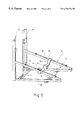
- FIG. 2 is a perspective view of the camera frame used in the apparatus of FIG. 1,
- FIG. 3 is a side elevation of the camera frame of FIG. 2, with means for fixing the frame to the window mullions,
- FIG. 4 is a schematic perspective view of the means for fixing the camera frame to the window mullions.
- FIG. 5 is a fragmentary view of the camera fixed to the camera frame of FIG. 3 .
- FIG. 1 The apparatus used for photographing window glass is shown in FIG. 1.
- a light box 11 is attached to a building maintenance unit (BMU) and contains a suitable light source such as a set of fluorescent tubes, and is covered with a diffuser. The light distribution across the diffuser should be as uniform as possible.
- a camera 12 is supported in a frame 13 in the BMU, below the light box 11 . The camera 12 and frame 13 are transported up and down the side of the building on the BMU. During the actual photography however, the camera frame 13 is locked to the side of the building by locating a suitable attachment (described below) within the window mullions. The operator stands within the BMU cradle.
- Photographic photography is performed at night, or in a darkened enclosure, to minimise effects of ambient light.
- the light reflected from the window 14 displays a uniform white background.
- small stones or defects cast a dark shadow.
- the stone appears as a double image.
- the first image is a direct image of the stone and the second image is the reflection of the stone in the back of the glass.
- the photographs are taken with focus set at the surface of the glass while the window 14 is illuminated by the light box 11 . All images are taken with the camera 12 set at the same working distance so that the overall object magnification is the same in all cases.
- the angle of tilt of the camera body, and the distance from the window to the front of the camera lens is determined by the choice of camera lens and the required size of the area photographed in each photographic exposure. The selection of specific values for camera tilt and working distance are discussed further below.
- the optimal camera working distance gives a demagnification of window to film of about 9 to 1 (on average).
- an image scanning device such as a microfiche reader
- a microfiche reader is then used to scan the films for defects.
- the microfiche reader has a 17 mm lens fitted and provides a magnification of 42 ⁇ .
- the overall magnification of window to observed film in fiche reader is therefore 42/9, or about 4.5 times. That is, the image on the fiche reader is 4.5 times actual size on the glass. Therefore the observer has a 4.5 times advantage in seeing defects in the glass as compared with direct visual observation of the glass as taught in PCT/AU93/00498.
- the camera of camera is determined by a need to maintain the window surface in focus over the whole image and to capture the maximum amount of information on each photograph.
- Wide format cameras have an advantage over 35 mm cameras as they use a larger film area and therefore capture more information per photograph. Because the photographs are taken at an oblique angle rather than straight-on to the window, it is necessary to tilt the camera lens in order to maintain the whole image in focus.
- a FUJI GX680 II camera was used since it has lens tilt capability and uses 120 roll film with a film area of 76 by 55 mm (four and half times the area of 35 mm film).
- the largest possible area of glass should be captured on each photographic film while still having enough resolution to see a stone of 70 ⁇ m size.
- a field on the glass of 600 mm width satisfies the resolution criterion while providing a reasonably large area of view.
- Lenses of short focal length are most desirable since with a short focal distance it is possible to bring the camera close to the glass and thus reduce the size of the frame required to hold the camera.
- lenses of very short focal length were found to have curved focus fields such that the images of the glass were unfocussed at the edges of the image field.
- the lens of shortest focal length that was found to have a suitably flat focal field was a 125 mm lens. For a 125 mm lens with a camera tilt angle of 30° and a horizontal field of 600 mm, the lens to window distance is 1018 mm.
- the lens tilt can be found empirically by focussing to the centre of the screen and adjusting the lens tilt until both bottom and top of the image are in focus at the same time.
- the amount of lens tilt required may also be calculated by using a ray tracing method.
- the lens tilt set empirically was found to be 3.2°. Within measurement error, the calculated tilt is equivalent to the empirical tilt setting).
- the camera 12 is therefore mounted on a camera frame 13 which is adapted to be releasably affixed to the building.
- the design of the camera frame 13 is shown schematically in FIG. 2, and in more detail in FIGS. 3, 4 , 5 .
- the frame 13 fixes the camera 12 at a set position and angle from the window 11 to be photographed.
- the frame 13 is attached to mullion tracks on the building. (On a building without mullion tracks, any suitable alternative method for attaching the frame to the building may be used).
- the frame 13 has several advantageous features, including
- the frame is affixed to the window by a set of four pneumatic rams.
- the rams pull up against clamps located within the mullion guides on the building.
- the frame has an adjustable width (adjustable distance between the uprights which clamp to the mullions, FIG. 2) to suit various window widths.
- the camera is mounted on a cross-beam which may slide back and forth.
- the camera in the back position is at the correct distance for photography.
- the camera is able to be moved forward so that the film may be changed by an operator standing within the BMU.
- FIG. 2 A schematic of the frame is shown in FIG. 2 .
- the frame is suitably built from a light material such as aluminium.
- Front and rear cross-beams 15 , 16 are welded at one end to the base member 17 of a triangular frame, and are slot and bolted at the other end to the base member 18 of a parallel triangular frame, to allow for adjustment of the frame spacing to individual window widths.
- the camera support 12 is mounted on a cross-beam 19 which is slot and bolted on both ends to respective slides 20 , 21 which ride on slide rails 22 , 23 of the triangular frames.
- the arrangement of the camera support cross-beam 19 is such that the camera 12 sits as low as possible within the frame 13 .
- the frame 13 is shown in greater detail in FIG. 3 .
- the camera 12 (drawn schematically) is shown in position on the frame, and also it is shown in more detail separately.
- the camera is at a tilt of 30° from the horizontal. Of the 30°, the design of the frame itself sets the camera slide at 18° from the horizontal. The remainder of the 30° is set by placing a spacer 26 on the camera support 19 which pivots the camera on that support.
- the camera 12 is normally secured to the support using its tripod attachment.
- the camera support and camera assembly can slide back and forth on a roller rail system 27 .
- the two rollers on each rail are bolted together using a 300 mm long piece of 100 ⁇ 12 mm plate.
- Each ram 30 is fixed to a set of two tie-rods 31 .
- the arrangement of the rams and tie-rods is shown schematically in FIG. 4 .
- Each tie rod 31 has a T-shaped end.
- the other end of the tie-rod is threaded and has an aluminium alignment knob 32 screwed onto it.
- the alignment knobs 32 are locked in position with locking nuts.
- the tie rods 31 are inserted into the mullion guides between the two windows with the T-shaped ends set vertically. The T ends are then rotated 90° so that the T ends are captive in the gap between the windows.
- Each of the alignment knobs has a hole drilled at one side so that an alignment pin 33 may be passed through both the top and bottom alignment knobs 32 of a particular ram assembly (FIG. 4 ). The alignment pin 33 locks the tie-rods 31 against any rotation so that the T ends remain in a horizontal position within the mullion guides.
- the tie rods 31 pass through slots in the upright members 24 , 25 of the transfer frames.
- the uprights 24 , 25 are slotted for two reasons. First, the slots are wide enough to allow the T ends on the tie rods to be pulled back through the uprights so that they will not catch on anything when the BMU is being launched over the side of the building. Secondly, although the uprights are set at a spacing which corresponds to the window width, the mullion tracks are not exactly straight and the slots allow some lateral movement of the tie-rods to compensate for the small differences in spacing of the mullion tracks as the frame is moved down the building.
- each ram push to lock on.
- the body of each ram is bolted to a ram support 34 .
- the thrust shaft 36 of each ram 30 is attached to a plate 37 through which the tie rods 31 are inserted.
- the tie rods are located in the mullion guides as described in the previous paragraph and turned. Compressed air is applied to the rams so that the ram thrusters 36 push out to cause the tie-rods 31 to be pulled outwards, which in turn, causes the T ends to pull up against the mullion guides at the back of the windows. This action pulls the frame against the front of the windows.
- the uprights 24 , 25 suitably have 3 mm thick neoprene rubber sheet covering the surface facing the window so that the uprights will not damage the window surface.
- the neoprene rubber provides a high friction surface which ensures that the frame does not slip when it is attached to the window.
- the rams 30 are bi-directional so that they may be released merely by reversing the direction of the compressed air.
- the air-lines are so arranged so that the camera frame can be disassembled if necessary.
- the air from the compressor passes through a four-way valve which is fixed to the front cross bar. By turning the handle on the four-way valve through 90° it is possible to reverse the air flow to the rams and so switch them from “off” to “on” and vice versa.
- the light box 11 is fixed to the BMU cradle in a position relative to the camera as shown in FIG. 1 .
- the light box is placed so as to provide illumination of the glass viewed by the camera (without obstructing the camera view of the window). To obtain the most even illumination the light box is tilted to 30° from the vertical.
- the camera is arranged to be as low as possible in the frame so that the light can also be kept as low as possible.
- window widths of up to 1800 mm three cameras 12 are required to order to be able to photograph the entire window width in a single session.
- the tie-rods are located the in mullion tracks, rotated and locked.
- the frame is now attached to the mullion tracks so that it cannot come away, although the tie-rods may slide down the tracks as the BMU cradle is lowered.
- the frame is lifted clear of the BMU cradle and fixed to the building by activating the pneumatic rams. After each photograph the pneumatic rams are released and the BMU is moved down into position for the next photograph.
- the films are viewed in a microfiche reader, typically in a viewing room, and scanned for defects.
- the film carriage of a conventional fiche reader is modified so that it will take 120 roll film, and has a guide track added.
- the guide track moves the film 6 mm horizontally at each step and 4.5 mm vertically at each row. These correspond to distances of 250 mm horizontally and 190 mm vertically on the fiche screen.
- the fiche screen has dimensions of 350 by 270 mm and such steps present each section of film in turn for examination and ensure that there is ample overlap between adjacent fields. Viewing on the fiche screen gives a 4.5 times advantage as compared with viewing the glass directly.
- Each 250 mm by 190 mm area on the fiche screen corresponds to an area of 54 mm by 40 mm on the actual window.
- the defects appear as white dot-pairs on the negatives.
- the defects appear as black dots when viewed directly by the camera, but this is a negative film so the contrast is reversed).
- the dot-pairs may appear as strong white dots or as weak white dots depending on the size of the stones in the window. Having scanned one section of film, the examiner moves the film carriage to the next point on the guide track, and so on until all the film has been scanned.
- the dot-pair distance is given by the formula:
- T is either the glass thickness or the distance of the stone from the back of the glass
- ⁇ is the light-to-film angle
- n is the refractive index of the glass.
- the light-to-film angle varies from point to point on the film although it has an average value of 30° (the camera tilt angle).
- a chart may be compiled for dot-pair distances (D) for marks on the surface of the glass for all film positions on the fiche guide track.
- the dot-pair distance chart is compiled from a photograph of a window which has had a set of marks placed on it with marker pen.
- the spacing between the dots is measured and is compared with the spacing expects for a mark on the surface of the glass. If the spacing is the same as that expected for a mark on the surface of the glass, these dots are ignored. However, if the spacing is less than expected for a surface mark, the position of the dot-pair is recorded on a log sheet. An x,y calibration chart is then used to relate the x,y position of the defect on the film to an x,y position on the window. The depth-in-glass of the defect is calculated by taking the ration of the spacing of the dot-pair to the spacing expected for a mark on the surface of the glass. If the depth-in-glass ratio is between 20% and 80%, the stone is in the tension zone of the toughened glass and could cause glass fracture. If the ratio is not between 20% and 80% the stone is in the compression zone and is of no particular interest.
- the abovedescribed technique was trialled on 72 windows, and appeared to find all stones of 70 ⁇ m diameter and greater.
- the results of the photographic method were checked visually using two times magnification on four of the 72 windows. The photographic method was found to have located all stones that could be found in the most careful visual examination.
- the progressive photography of window glass on a building may be automated or semi-automated, using computer control.
- a microprocessor control circuit may be used to repeatedly release the tie rods, raise or lower the camera frame a predetermined distance, reapply the tie rods and fix the frame relative to the window, take photographs, and repeat the process until an entire column of windows has been photographed.
- the optical examination of the photographic film images may be performed, either on site or elsewhere, by automated or semi-automated inspection apparatus.
- Such apparatus can use software to perform pattern recognition to locate pairs of images on the film corresponding to NiS stones and their reflections.
- the frame On a building without mullion tracks, the frame may be suitably attached to the building by use of vacuum pads which are affixed to the windows on either side of the window to be photographed.
- the vacuum pads can be activated using a vacuum pump carried on the BMU.
- step of photographing portions of the glass onto photographic film can be replaced by capturing images of the glass portions in digital data form (e.g. using a digital camera) providing that the required degree of resolution is achieved.
Landscapes
- Physics & Mathematics (AREA)
- Health & Medical Sciences (AREA)
- Life Sciences & Earth Sciences (AREA)
- Chemical & Material Sciences (AREA)
- Analytical Chemistry (AREA)
- Biochemistry (AREA)
- General Health & Medical Sciences (AREA)
- General Physics & Mathematics (AREA)
- Immunology (AREA)
- Pathology (AREA)
- Investigating Materials By The Use Of Optical Means Adapted For Particular Applications (AREA)
Applications Claiming Priority (3)
| Application Number | Priority Date | Filing Date | Title |
|---|---|---|---|
| AUPO0235A AUPO023596A0 (en) | 1996-05-31 | 1996-05-31 | Detection of defects in glass |
| AUP00235 | 1996-05-31 | ||
| PCT/AU1997/000336 WO1997046869A1 (en) | 1996-05-31 | 1997-05-28 | Detection of defects in glass |
Publications (1)
| Publication Number | Publication Date |
|---|---|
| US6236734B1 true US6236734B1 (en) | 2001-05-22 |
Family
ID=3794554
Family Applications (1)
| Application Number | Title | Priority Date | Filing Date |
|---|---|---|---|
| US09/194,399 Expired - Fee Related US6236734B1 (en) | 1996-05-31 | 1997-05-28 | Detection of defects in glass |
Country Status (6)
| Country | Link |
|---|---|
| US (1) | US6236734B1 (id) |
| CN (1) | CN1220730A (id) |
| AU (1) | AUPO023596A0 (id) |
| ID (1) | ID17118A (id) |
| WO (1) | WO1997046869A1 (id) |
| ZA (1) | ZA974482B (id) |
Cited By (5)
| Publication number | Priority date | Publication date | Assignee | Title |
|---|---|---|---|---|
| US20020057339A1 (en) * | 2000-10-20 | 2002-05-16 | S&S X-Ray Products, Inc. | High resolution sheet metal scanner with independent tracking light source |
| US20030222002A1 (en) * | 2002-06-03 | 2003-12-04 | Meyer David S. | Methods and systems for small parts inspection |
| US20080060383A1 (en) * | 2005-01-12 | 2008-03-13 | Glassiq Gmbh & Co. Kg | Method for Examining the Presence of Nickle Sulphide Inclusions in Tempered Safety Glass and Method Therefor |
| DE102014005932A1 (de) | 2014-04-25 | 2015-10-29 | Boraident Gmbh | Verfahren und Vorrichtung zur Selektion und Detektion von Nickelsulfid-Einschlüssen in Glas |
| CN112858228A (zh) * | 2021-01-22 | 2021-05-28 | 西安应用光学研究所 | 一种大尺寸光学窗口零件透射分辨率测量装置及测量方法 |
Families Citing this family (8)
| Publication number | Priority date | Publication date | Assignee | Title |
|---|---|---|---|---|
| JP5418983B2 (ja) * | 2010-02-26 | 2014-02-19 | 旭硝子株式会社 | 矩形板状物の割れ検査方法及び検査装置 |
| CN106248684B (zh) | 2015-06-03 | 2019-12-17 | 法国圣戈班玻璃公司 | 用于检测透明基底的内部瑕疵的光学装置及方法 |
| CN109332100A (zh) * | 2018-12-26 | 2019-02-15 | 苏州富强科技有限公司 | 双阀点胶装置 |
| CN112906422A (zh) * | 2019-11-15 | 2021-06-04 | 孙兴珍 | 状态数据实时鉴别系统 |
| CN110907474A (zh) * | 2019-12-10 | 2020-03-24 | 江苏奥蓝工程玻璃有限公司 | 一种玻璃镀膜视觉检测用缺陷采集装置 |
| CN111948227B (zh) * | 2020-08-15 | 2021-10-12 | 深圳市信濠光电科技股份有限公司 | 一种触摸屏裂纹检测仪 |
| CN113189126A (zh) * | 2021-04-30 | 2021-07-30 | 河北南玻玻璃有限公司 | 一种浮法玻璃微小固体疵点的检测分析方法 |
| CN118330194B (zh) * | 2024-06-13 | 2024-08-30 | 山东鲁玻玻璃科技有限公司 | 一种硼硅玻璃制造用监测分析系统 |
Citations (7)
| Publication number | Priority date | Publication date | Assignee | Title |
|---|---|---|---|---|
| US4076426A (en) * | 1976-06-29 | 1978-02-28 | Rca Corporation | Method for inspecting cathode-ray-tube window for objectionable cord |
| US4160601A (en) | 1978-02-24 | 1979-07-10 | Nasa | Biocontamination and particulate detection system |
| EP0282687A2 (en) | 1987-03-20 | 1988-09-21 | Nippon Kokan Kabushiki Kaisha | Intrapipe spot examination pig device |
| US5073707A (en) * | 1990-05-24 | 1991-12-17 | Laser Labs, Inc. | Window-transmittance meter having entrance detector |
| WO1994008229A1 (en) | 1992-09-29 | 1994-04-14 | The University Of Queensland | Detection of defects in glass |
| JPH08304048A (ja) | 1995-04-28 | 1996-11-22 | Toppan Printing Co Ltd | 凹凸欠陥検査装置 |
| US5841530A (en) * | 1995-12-29 | 1998-11-24 | Orfield Lab Inc | Industrial viewing station for inspection of defects |
-
1996
- 1996-05-31 AU AUPO0235A patent/AUPO023596A0/en not_active Abandoned
-
1997
- 1997-05-22 ZA ZA9704482A patent/ZA974482B/xx unknown
- 1997-05-28 ID IDP971807A patent/ID17118A/id unknown
- 1997-05-28 CN CN97195131A patent/CN1220730A/zh active Pending
- 1997-05-28 US US09/194,399 patent/US6236734B1/en not_active Expired - Fee Related
- 1997-05-28 WO PCT/AU1997/000336 patent/WO1997046869A1/en not_active Ceased
Patent Citations (7)
| Publication number | Priority date | Publication date | Assignee | Title |
|---|---|---|---|---|
| US4076426A (en) * | 1976-06-29 | 1978-02-28 | Rca Corporation | Method for inspecting cathode-ray-tube window for objectionable cord |
| US4160601A (en) | 1978-02-24 | 1979-07-10 | Nasa | Biocontamination and particulate detection system |
| EP0282687A2 (en) | 1987-03-20 | 1988-09-21 | Nippon Kokan Kabushiki Kaisha | Intrapipe spot examination pig device |
| US5073707A (en) * | 1990-05-24 | 1991-12-17 | Laser Labs, Inc. | Window-transmittance meter having entrance detector |
| WO1994008229A1 (en) | 1992-09-29 | 1994-04-14 | The University Of Queensland | Detection of defects in glass |
| JPH08304048A (ja) | 1995-04-28 | 1996-11-22 | Toppan Printing Co Ltd | 凹凸欠陥検査装置 |
| US5841530A (en) * | 1995-12-29 | 1998-11-24 | Orfield Lab Inc | Industrial viewing station for inspection of defects |
Cited By (8)
| Publication number | Priority date | Publication date | Assignee | Title |
|---|---|---|---|---|
| US20020057339A1 (en) * | 2000-10-20 | 2002-05-16 | S&S X-Ray Products, Inc. | High resolution sheet metal scanner with independent tracking light source |
| US6958769B2 (en) * | 2000-10-20 | 2005-10-25 | S&S X-Ray Products, Inc. | High resolution sheet metal scanner with independent tracking light source |
| US20030222002A1 (en) * | 2002-06-03 | 2003-12-04 | Meyer David S. | Methods and systems for small parts inspection |
| US6879389B2 (en) | 2002-06-03 | 2005-04-12 | Innoventor Engineering, Inc. | Methods and systems for small parts inspection |
| US20080060383A1 (en) * | 2005-01-12 | 2008-03-13 | Glassiq Gmbh & Co. Kg | Method for Examining the Presence of Nickle Sulphide Inclusions in Tempered Safety Glass and Method Therefor |
| DE102014005932A1 (de) | 2014-04-25 | 2015-10-29 | Boraident Gmbh | Verfahren und Vorrichtung zur Selektion und Detektion von Nickelsulfid-Einschlüssen in Glas |
| WO2015162303A1 (de) | 2014-04-25 | 2015-10-29 | Boraident Gmbh | Verfahren und vorrichtung zum erkennen von nickelsulfid-einschlüssen in einer glasplatte |
| CN112858228A (zh) * | 2021-01-22 | 2021-05-28 | 西安应用光学研究所 | 一种大尺寸光学窗口零件透射分辨率测量装置及测量方法 |
Also Published As
| Publication number | Publication date |
|---|---|
| CN1220730A (zh) | 1999-06-23 |
| ZA974482B (en) | 1997-12-29 |
| ID17118A (id) | 1997-12-04 |
| WO1997046869A1 (en) | 1997-12-11 |
| AUPO023596A0 (en) | 1996-06-27 |
Similar Documents
| Publication | Publication Date | Title |
|---|---|---|
| US6236734B1 (en) | Detection of defects in glass | |
| TWI264532B (en) | Substrate inspection device | |
| US5367174A (en) | Defect detecting device for two-layer parts, in particular for solar cells | |
| JP5348765B2 (ja) | 平板状透明体の微小凹凸欠陥検査方法及び装置 | |
| US5991038A (en) | Surface pattern unevenness detecting method and apparatus | |
| CN214097211U (zh) | 一种透明平板玻璃的缺陷检测装置 | |
| KR101015807B1 (ko) | 표면 검사 장치 및 표면 검사 방법 | |
| JPS61256237A (ja) | 周期性パタ−ンの欠陥検査方法 | |
| AU732132B2 (en) | Detection of defects in glass | |
| EP0985140B1 (de) | Linsen-prüfgerät | |
| CN213209949U (zh) | 显示面板缺陷检测装置 | |
| EP0338442B1 (en) | A method and apparatus for the inspection of specularly reflective surfaces | |
| CN211402165U (zh) | 外观瑕疵检测装置 | |
| CN211877794U (zh) | 一种管线环焊缝宏观金相拍摄分析装置 | |
| KR101391312B1 (ko) | 백라이트유닛 불량검사용 카메라 조립체 | |
| JP2000258583A (ja) | 沸騰水型核燃料集合体の燃料棒ギャップ測定装置 | |
| CN218823993U (zh) | 显示面板光学检测装置 | |
| CN116297540A (zh) | 检测设备 | |
| CN211374539U (zh) | 外观瑕疵检测装置 | |
| KR100748108B1 (ko) | 음극선관용 패널의 검사장치 및 그 방법 | |
| DE19823844C1 (de) | Linsen-Prüfgerät | |
| JP2021148794A (ja) | 透過光学系の検査装置 | |
| KR102631780B1 (ko) | 가변 및 오토 타입 필름 처짐 검사기 | |
| JP3357967B2 (ja) | レンチキュラーレンズシートの欠陥検査装置 | |
| CN223139430U (zh) | 一种专业检测不透光壳件内外观的视觉检测设备 |
Legal Events
| Date | Code | Title | Description |
|---|---|---|---|
| AS | Assignment |
Owner name: QUEENSLAND, UNIVERSITY OF, THE, AUSTRALIA Free format text: ASSIGNMENT OF ASSIGNORS INTEREST;ASSIGNOR:BARRY, JOHN COTTER;REEL/FRAME:009852/0307 Effective date: 19981127 |
|
| REMI | Maintenance fee reminder mailed | ||
| LAPS | Lapse for failure to pay maintenance fees | ||
| STCH | Information on status: patent discontinuation |
Free format text: PATENT EXPIRED DUE TO NONPAYMENT OF MAINTENANCE FEES UNDER 37 CFR 1.362 |
|
| FP | Lapsed due to failure to pay maintenance fee |
Effective date: 20050522 |