US626149A - L desmarais - Google Patents
L desmarais Download PDFInfo
- Publication number
- US626149A US626149A US626149DA US626149A US 626149 A US626149 A US 626149A US 626149D A US626149D A US 626149DA US 626149 A US626149 A US 626149A
- Authority
- US
- United States
- Prior art keywords
- needles
- warp
- threads
- cylinders
- weft
- Prior art date
- Legal status (The legal status is an assumption and is not a legal conclusion. Google has not performed a legal analysis and makes no representation as to the accuracy of the status listed.)
- Expired - Lifetime
Links
Images


Classifications
-
- D—TEXTILES; PAPER
- D03—WEAVING
- D03C—SHEDDING MECHANISMS; PATTERN CARDS OR CHAINS; PUNCHING OF CARDS; DESIGNING PATTERNS
- D03C15/00—Pattern cards or chains
- D03C15/04—Cards or paper perforated to indicate pattern
-
- D—TEXTILES; PAPER
- D03—WEAVING
- D03C—SHEDDING MECHANISMS; PATTERN CARDS OR CHAINS; PUNCHING OF CARDS; DESIGNING PATTERNS
- D03C3/00—Jacquards
- D03C3/02—Single-lift jacquards
Definitions
- Our invention relates to looms for weaving ornamented or figured fabrics, and has for its object to provide a machine of the aboveindicatedclass which will enable the length and width of the design or pattern to be varied without varying the pattern-band or selecting mechanism which controls the production of the design.
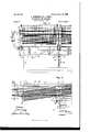
- FIG. 1 is a side elevation, partly in section, of our improved weaving apparatus.
- Fig.1 is the continuation of Fig. 1.
- Fig. 2 is a plan of the same from above.
- Fig. 2 is the continuation of Fig. 2.
- Fig. 3 is acrosssection on line 3 30f Fig. 1.
- Fig. 4 shows separately one of the heddles or needles used in the apparatus.
- Fig. 5 is a longitudinal section and plan of a nipper which may be used instead of shuttles; and
- Figs. 6 and 7 are respectively a longitudinal section and a transverse section on an enlarged scale, (the section Fig. 7 being taken on line 7 7 of Fig. 2,) showing the details of some of the working parts of the apparatus.
- A is a perforated metallic cylinder, which may be repeated or duplicated a certain number of times according to the pattern to be woven in the length of the apparatus.
- a and A are two A and A.
- the size of the perforations and their distance from each other are arbitrary; but in all cases they are of equal size and distributed uniformly over the entire surface of the cylinder or cylinders.
- Figs. 6 and 7 is a cloth or canvas band substituted for the ruled paper of the cardsetting such as used in Jacquard looms and made sufficiently transparent to allow the perforations of the cylinder A to be seen through it. It is pierced with holes at places where the warp-threads have to be lowered, such holes being arranged to correspond with perforations in the cylinders. As will be seen, some of these perforations are covered by a non-perforated part of the band or cover. This cover B completely surrounds the cylinder and is suitably secured thereon.
- C C are the needles, through the eyes a of which, Fig. 4, are passed the warp-threads 00.
- These needles which are operated with an ascending and descending movement, are equal in number to the perforations in one longitudinal row of the cylinder and are arranged vertically above the axis thereof. They are provided at several places with guides formed of perforated metallic bars (1 d d Two of the metallic bars d d are carried on a frame D, actuated, as hereinafter described with a reciprocating rectilinear movement.
- the bar cl is a fixture, and above it is a solid metallic cross-bar d serving as aback-stop forthe needles C.
- the intervals between the metallic bars d d and between the bar (1 and cross-bar d can be regulated as desired by means of the rods e e on which they are screwed, one set of which rods connects the frame D to the mechanism which operates it and the other set being firmlysecured in the support E of the cylindersAA.
- the rods 6 serve also as guides for the frame D and the rods e pass through a guide at their lower part.
- the vertical alternating movement of the frame D is obtained by means of a set of bellcrank levers f f", fulerumed on the support E, and linksfconnecting said levers,the outer arms of the levers f being attached to the rods 6 and the inner ends of the levers f are drawn downward by a spring G, secured to a head G, carried by the lower end of one of the rods 0 and loosely engaged by the inner ends of the levers f, while a lever g, Fig. 3,
- Thedriving-shaft H extends toward one end of the apparatus, where it carries a hand-wheel V or pulleys for power-driving. Foreach weft the driving-shaft is arranged to make one complete revolution.
- the support E of the cylinders turns on a pivot I in a pedestal 1 of any suitable construction rigidly secured upon the lower.
- ratchet-wheels a On the perforated cylinders A A are secured ratchet-wheels a, Figs. 2, G, and 7, with which pawls engage, operated by cams m on the driving-shaft II.
- This mechanism has for its object to cause an intermittent rotation of the cylinders A A, and in order that the rows of perforations thereof may arrive in succession under the needles 0 the teeth of the ratchet-wheels correspond with the spacing of the rows of perforations.
- L is a roller or beam from which the warpthreads are unwound, and these threads pass through the needle-eyes c, the tension of the warp-threads being maintained by asprin g r, acting on the roller L.
- M is the cloth-roller upon which the woven fabric is wound.
- the taking off is controlled by an endless screw it upon the shaft II, operating a helical wheel it, upon the axis of which is wound a cord Z Z, passing over a pulley n keyed upon the axle of the roller M.
- the speed of winding may be accelerated or retarded according to the reduction required in the woof. It will be obvious that if the speed of winding or of moving the fabric longitudinally of the warp is reduced while the number of wefts inserted per minute remains the same the wefts will be closer together than if the speed of winding is increased while the number of weft insertions per minute remains constant.
- the distance between the wefts can be reduced or increased, as desired.
- N is the beater-comb, Fig. 3, hinged at 0, through which the warp-threads are passed.
- a spring 0' constantly withdraws the beatercomb toward the roller M, while it is drawn in the opposite direction by a cord attached to a lever 17, operated by means of a cam 11, keyed on the driving-shaft H.
- the above-described first part of our apparatus operates as follows:
- the warp-threads m, unwound from the roller L, are passed through the needles 0 and the beatencomb N and secured at their ends on the clothroller M.
- the cylinders A A are inclined according to the desired reduction in the width of the fabric, and the speed of winding on the roller M is adjusted according to this reduction, so that when the fabric is narrowed the wefts will be brought closer together in the same ratio as the warp-threads, whereby the original design will be produced upon a smaller scale.
- the driving-shaft H is turned in such a manner that the frame D, and consequently the needles C, are raised, all the warp-threads being thus lifted.
- One turn of the shaft II is then made, causing the frame D to be lowered by means of its cam h, and the needles 0, which come over the uncovered perforations of the cylinders A, pass into them, while the other needles remain raised by sliding in the retaining-band F.
- a shed is then formed between the needles and the beater-comb N.
- a weft is passed through this shed by means of the usual shuttles or by means of the particular weft-nippers hereinafter described, and the weft is forced against those previously inserted by the action of the beater-comb N.
- a corresponding quantity of fabric is wound upon the roller M.
- the frame D is afterward raised, so as to lift the needles engaged in the cylinder or cylinders, and these latter by reason of their click mechanism turn so as to present a new row of perforations to the needles 0.
- This set of operations is repeated at each turn of the driving-shaft H until all the rows of perforations of the cylinders have passed in succession under the needles.
- the warp-threads may be differently raised and lowered or selected. This depends solely on the cover or cloth band B around the cylinder, which cover is adapted to the particular fabric to be produced.
- any suitable shuttle or other mechanism may be employed, We prefer, however, the mechanism to be described presently,which is particularly adapted for the purpose of producing a sample that is, a fabric which while having no border or selvage will exhibit the same design or pattern as the complete fabric.
- a support 0 secured upon the pedestal 1 of the apparatus is arranged to revolve a circular plate P, carrying a series of springspindles holding as many reels q of different colors as may be required.
- a tubular elastic needle 5 is provided on the plate P, so as to permit a portion of thread to extend through it.
- a weftnipper S, Fig. 5 formed of a metallic rod terminating in a clip .9, is arranged to travel horizontally to and from the plate in a guide Q, placed on the support 0, in such a manner as to prevent the nipper from turning on its
- the nipper is operated by a camu, Fig.
- the weft-nipper S (or the'shuttle used in its stead) as a rule has a thickness of only two or three millimeters, so that it can readily carry the ,weft through the shed.
- the scissors are operated in any suitable manner for instance, by means of projections .2 on the beater-comb N, which move the springpressed blade o toward the stationary blade U2, which is secured to the support 0.
- the scissors 'v o are located adjacent to the outermost warp-threads.
- the beater-comb N is, Fig. l, at the left of the weft-inserting device and of the frame 0.
- the beater-comb moves to the right, and in so doing its projections z weftclose to those previously inserted and reaches the position shown in Fig. l.
- the weft-threads moved automatically by .the rollers may be presented indiscriminately to the clip, or' by turning the plate P by hand the reel of the right color may be brought opposite the clip 8.
- the fabric produced by using the above-described nipper has no border or selvage, but
- a loom comprising means for holding the warp in a predetermined direction, a pattern-cylinder extending longitudinally of the warp and carrying warp needles or heddles,
- a loom having means for holding the warp-threads, and a series of movable heddles or needles for individually raising and lowering the warp-threads, said heddles or needles being carried in one and the same plane to form a longitudinal row or Series,
- said series of needles being mounted to turn bodily about an axis standing at an angle to the plane of the warp-threads, whereby the series of needles may be caused to assume a line more or less oblique relatively to the direction of the warp-threads.
- a weaving apparatus having means for .holding the warps in a predetermined direction, a frame mounted to swing about an axis approximately perpendicular to said dire-ction, a series of needles or the like carried 1) I11 testimony whereof we have signed our said frame and engaging the warps to bring names to this specification in the presence of [0 them into the loweror upper position to form two subscribing witnesses.
Landscapes
- Engineering & Computer Science (AREA)
- Textile Engineering (AREA)
- Woven Fabrics (AREA)
Description
No. 626,149. Patented May 30, I899. L. DESMABAIS & L. CANAL.
APPARATUS FOB WEAVING.
(Application filed Dec. 10, 1896.) (No Model.) 4 Sheets-Shoat Fly 1.
I (El/T0175. W/ TAIE's jw a er No. 626,149. Patented May 30, I899. L. DESMARAIS &. L. CANAL. APPARATUS FER WEAVING.
(Application filed Dec. 10, 1896.) (\No Model.) 4 Sheets-Sheet 2.
fly. 1.
N INVENTORS, wrmzssrs. 5914mm m: NORRIS vz-rzns co. PHOTD-LITHO.WASH1NG7ON, n c.
No. 626,149. Patented May 30, I899.
L. DESMARAIS &. L. CANAL.
APPARATUS FOR WEAVING.
(Application filed Dec. 10, 1896.) (No Model.)
4 Sheets-Sheet 3.
. 7 I I v A j g W/77VESSES, gilgmmfls.
E nrronurs ms norms Pzrzas cu. Pnmaumm-wumnaw n. Q
No. 626,l49. Patented May 30, I899. L. DESMARAIS & L. CANAL.
APPARATUS FOR WEAVING.
(Application filed Dec; 10, 1898.) I 1 (No Model.) 4 Sheets-Sheat 4.
I H H! llllll l MI VE N T0175.
. -WW 0% %M WITNESSES,
, u c. THE nonms PEYERS co, vucroumu, wAsnmo'rou U ITED STATES,
P TENT OFFICE.
LFO'N DESMARAIS AND LOUIS CANAL, OF PARIS, FRANCE.
APPARATUS FOR WEAVING.
SPECIFICATION forming part of Letters Patent No. 626,149, dated May 30, 1899.
Application filed December 10, 1896. Serial No. 615,114. (No model.)
To all whom it may concern:
Be it known that we, LEON DESMARAIS, manufacturer, and LOUIS CANAL, engineer, citizens of the French Republic, residing at Paris, France, have invented an Apparatus for Weaving all Kinds of Textile Materials, of which the following is a specification, and for which patents have been obtained in France, No. 258,916, dated August 18, 1896; in Belgium, No. 124,533, dated November 11, 1896; in Great Britain,No. 25,663, dated November 14, 1896; in Austria, No. 46/5,015, dated November 1.6, 1896; in Germany, No. 98,299, dated November16, 1896; in Spain, No. 19,963, dated November 19, 1896; in Switzerland, No. 13,774, dated February 11, 1897, and in Italy, No. 43,856, dated February 19, 1897.
Our invention relates to looms for weaving ornamented or figured fabrics, and has for its object to provide a machine of the aboveindicatedclass which will enable the length and width of the design or pattern to be varied without varying the pattern-band or selecting mechanism which controls the production of the design.
To this end our invention consists of certain features of construction, as will be hereinafter described and claimed.
In order to clearly explain the construction and working of our apparatus, reference is made in the following description to the accompanyingidrawings, upon which- Figure 1 is a side elevation, partly in section, of our improved weaving apparatus. Fig.1 is the continuation of Fig. 1. Fig. 2 is a plan of the same from above. Fig. 2 is the continuation of Fig. 2. Fig. 3 is acrosssection on line 3 30f Fig. 1. Fig. 4 shows separately one of the heddles or needles used in the apparatus. Fig. 5 is a longitudinal section and plan of a nipper which may be used instead of shuttles; and Figs. 6 and 7 are respectively a longitudinal section and a transverse section on an enlarged scale, (the section Fig. 7 being taken on line 7 7 of Fig. 2,) showing the details of some of the working parts of the apparatus.
In Figs. 1, 1, 2, 2, and 3, A is a perforated metallic cylinder, which may be repeated or duplicated a certain number of times according to the pattern to be woven in the length of the apparatus. As shown'in the drawings, by way of example,there are two A and A. In the case of several cylinders they are arranged in longitudinal succession and mounted on axes in friction-bearings. The size of the perforations and their distance from each other are arbitrary; but in all cases they are of equal size and distributed uniformly over the entire surface of the cylinder or cylinders.
B, Figs. 6 and 7, is a cloth or canvas band substituted for the ruled paper of the cardsetting such as used in Jacquard looms and made sufficiently transparent to allow the perforations of the cylinder A to be seen through it. It is pierced with holes at places where the warp-threads have to be lowered, such holes being arranged to correspond with perforations in the cylinders. As will be seen, some of these perforations are covered by a non-perforated part of the band or cover. This cover B completely surrounds the cylinder and is suitably secured thereon.
C C are the needles, through the eyes a of which, Fig. 4, are passed the warp-threads 00. These needles, which are operated with an ascending and descending movement, are equal in number to the perforations in one longitudinal row of the cylinder and are arranged vertically above the axis thereof. They are provided at several places with guides formed of perforated metallic bars (1 d d Two of the metallic bars d d are carried on a frame D, actuated, as hereinafter described with a reciprocating rectilinear movement. The bar cl is a fixture, and above it is a solid metallic cross-bar d serving as aback-stop forthe needles C. It will be seen that the intervals between the metallic bars d d and between the bar (1 and cross-bar d can be regulated as desired by means of the rods e e on which they are screwed, one set of which rods connects the frame D to the mechanism which operates it and the other set being firmlysecured in the support E of the cylindersAA. The rods 6 serve also as guides for the frame D and the rods e pass through a guide at their lower part. It will be seen that the frames carrying the needles always remain in the same relation to the axes of the cylinders that is, they move in unison with said cylinders when the latter are adjustedso that their axes will assume different inclinations relatively to the direction of the warp-threads. For the sake of clearness we have shown only two warps in the drawings. For the same reason we have represented the cylinders A A in Figs. 1 and 1 as disposed with their axes parallel to the direction of the warps;
ment of the frame D, unless resistance is offered to the needles, in which case they simply slide within the said band.
The vertical alternating movement of the frame D is obtained by means of a set of bellcrank levers f f", fulerumed on the support E, and linksfconnecting said levers,the outer arms of the levers f being attached to the rods 6 and the inner ends of the levers f are drawn downward by a spring G, secured to a head G, carried by the lower end of one of the rods 0 and loosely engaged by the inner ends of the levers f, while a lever g, Fig. 3,
and a cam 71 Fig. 2, keyed on the driving- 1 shaft 11, draw the head G upward. Thedriving-shaft H extends toward one end of the apparatus, where it carries a hand-wheel V or pulleys for power-driving. Foreach weft the driving-shaft is arranged to make one complete revolution.
The support E of the cylinders turns on a pivot I in a pedestal 1 of any suitable construction rigidly secured upon the lower.
frame K of the apparatus, by which arrangement the support and cylinders are .allowed to be turned to an oblique position to an extent proportionate to the reduction to be obtained in the warpthat is, in the width of the fabric the position required being regulated by means of studs 10 w, engaging in grooved segments y y, formed on the support E and having as their center the axis of the pivot I.
On the perforated cylinders A A are secured ratchet-wheels a, Figs. 2, G, and 7, with which pawls engage, operated by cams m on the driving-shaft II. This mechanism has for its object to cause an intermittent rotation of the cylinders A A, and in order that the rows of perforations thereof may arrive in succession under the needles 0 the teeth of the ratchet-wheels correspond with the spacing of the rows of perforations.
L is a roller or beam from which the warpthreads are unwound, and these threads pass through the needle-eyes c, the tension of the warp-threads being maintained by asprin g r, acting on the roller L.
M is the cloth-roller upon which the woven fabric is wound. The taking off is controlled by an endless screw it upon the shaft II, operating a helical wheel it, upon the axis of which is wound a cord Z Z, passing over a pulley n keyed upon the axle of the roller M. By taking off the pulley n and substituting another pulley of different diameter the speed of winding may be accelerated or retarded according to the reduction required in the woof. It will be obvious that if the speed of winding or of moving the fabric longitudinally of the warp is reduced while the number of wefts inserted per minute remains the same the wefts will be closer together than if the speed of winding is increased while the number of weft insertions per minute remains constant. Thus by increasing or decreasing the winding-speed while leaving constant the number of wefts inserted per minute the distance between the wefts can be reduced or increased, as desired.
N is the beater-comb, Fig. 3, hinged at 0, through which the warp-threads are passed. A spring 0' constantly withdraws the beatercomb toward the roller M, while it is drawn in the opposite direction by a cord attached to a lever 17, operated by means of a cam 11, keyed on the driving-shaft H.
The above-described first part of our apparatus operates as follows: The warp-threads m, unwound from the roller L, are passed through the needles 0 and the beatencomb N and secured at their ends on the clothroller M. The cylinders A A are inclined according to the desired reduction in the width of the fabric, and the speed of winding on the roller M is adjusted according to this reduction, so that when the fabric is narrowed the wefts will be brought closer together in the same ratio as the warp-threads, whereby the original design will be produced upon a smaller scale. The driving-shaft H is turned in such a manner that the frame D, and consequently the needles C, are raised, all the warp-threads being thus lifted. One turn of the shaft II is then made, causing the frame D to be lowered by means of its cam h, and the needles 0, which come over the uncovered perforations of the cylinders A, pass into them, while the other needles remain raised by sliding in the retaining-band F. A shed is then formed between the needles and the beater-comb N. A weft is passed through this shed by means of the usual shuttles or by means of the particular weft-nippers hereinafter described, and the weft is forced against those previously inserted by the action of the beater-comb N. A corresponding quantity of fabric is wound upon the roller M. The frame D is afterward raised, so as to lift the needles engaged in the cylinder or cylinders, and these latter by reason of their click mechanism turn so as to present a new row of perforations to the needles 0. This set of operations is repeated at each turn of the driving-shaft H until all the rows of perforations of the cylinders have passed in succession under the needles. At each set of ITO operations the warp-threads may be differently raised and lowered or selected. This depends solely on the cover or cloth band B around the cylinder, which cover is adapted to the particular fabric to be produced.
It will be readily understood that the combination of the movements of the needles and of the cylinders allows the manufacture of all kinds of fabrics, which up to the present only the use of the jacquard mechanism has been able to produce.
For inserting the weft any suitable shuttle or other mechanism may be employed, We prefer, however, the mechanism to be described presently,which is particularly adapted for the purpose of producing a sample that is, a fabric which while having no border or selvage will exhibit the same design or pattern as the complete fabric.
axis.
Upon a support 0, secured upon the pedestal 1 of the apparatus, is arranged to revolve a circular plate P, carrying a series of springspindles holding as many reels q of different colors as may be required. For each reel a tubular elastic needle 5 is provided on the plate P, so as to permit a portion of thread to extend through it. Opposite the plate a weftnipper S, Fig. 5, formed of a metallic rod terminating in a clip .9, is arranged to travel horizontally to and from the plate in a guide Q, placed on the support 0, in such a manner as to prevent the nipper from turning on its The nipper is operated by a camu, Fig. 3, and a set of compound levers u and cords or runners a passing over suitably-arranged pulleysj When the nipper S comes up to the plate P, its clip 5' slides over the corresponding needle .9 and grips the weftthread, which by the return movement is drawn out and crosses the warp. It is then conveyed to the place it is to occupy in the fabric by the beater-comb N, previously referred to. At the same moment scissors o '0 out the weft-thread at both ends, and after the formation of another shed the nipper S is again passed through the warp and seizes a new weft-thread, which is similarly placed in position by the beater-comb, and so on. The weft-nipper S (or the'shuttle used in its stead) as a rule has a thickness of only two or three millimeters, so that it can readily carry the ,weft through the shed. The scissors are operated in any suitable manner for instance, by means of projections .2 on the beater-comb N, which move the springpressed blade o toward the stationary blade U2, which is secured to the support 0. The scissors 'v o are located adjacent to the outermost warp-threads. At the time the weft is inserted the beater-comb N is, Fig. l, at the left of the weft-inserting device and of the frame 0. Then the beater-comb moves to the right, and in so doing its projections z weftclose to those previously inserted and reaches the position shown in Fig. l.
The weft-threads moved automatically by .the rollers may be presented indiscriminately to the clip, or' by turning the plate P by hand the reel of the right color may be brought opposite the clip 8.
The fabric produced by using the above-described nipper has no border or selvage, but
as only a sample is required this is not ma terial, and the character of the fabric may readily be judged from the sampling. The process, it may be added, is extremely simple.
In conclusion, we do not limit ourselves to the forms and dimensions shown on the drawings, and, moreover, we reserve the right to produce the various mechanical movements necessary for the working of our apparatus in any other way than that described, as the principle on which our invention is based will not be thereby affected.
Having thus described our invention, we claim as new and desire to secure by Letters Patent 1 1. A loom comprising means for holding the warp in a predetermined direction, a pattern-cylinder extending longitudinally of the warp and carrying warp needles or heddles,
means for rotating said cylinder, the cylin-/ forming mechanism, and means for inserting the weft.
3. The combination of a perforated rotary cylinder, a frame movable toward and from the cylinder and carrying a resilient mate-- rial, and needles passed through and movably held Joy the resilient material, substantially as described.
4:. A loom, having means for holding the warp-threads, and a series of movable heddles or needles for individually raising and lowering the warp-threads, said heddles or needles being carried in one and the same plane to form a longitudinal row or Series,
said series of needles being mounted to turn bodily about an axis standing at an angle to the plane of the warp-threads, whereby the series of needles may be caused to assume a line more or less oblique relatively to the direction of the warp-threads.
5. A weaving apparatus having means for .holding the warps in a predetermined direction, a frame mounted to swing about an axis approximately perpendicular to said dire-ction, a series of needles or the like carried 1) I11 testimony whereof we have signed our said frame and engaging the warps to bring names to this specification in the presence of [0 them into the loweror upper position to form two subscribing witnesses.
a shed, the series of needles forming a row LEON DESMARAIS.
5 normally at an angle with thedireetionof the LOUIS CANAL.
warps, and mechanism for selecting the nee- Witnesses: dles, said mechanism being carried by said LEON FRANOKEN,
frame, substantially as described. A EDWARD '1. MACLEAN.
Publications (1)
| Publication Number | Publication Date |
|---|---|
| US626149A true US626149A (en) | 1899-05-30 |
Family
ID=2694751
Family Applications (1)
| Application Number | Title | Priority Date | Filing Date |
|---|---|---|---|
| US626149D Expired - Lifetime US626149A (en) | L desmarais |
Country Status (1)
| Country | Link |
|---|---|
| US (1) | US626149A (en) |
Cited By (3)
| Publication number | Priority date | Publication date | Assignee | Title |
|---|---|---|---|---|
| US2469200A (en) * | 1946-09-11 | 1949-05-03 | Matweeff Paul | Harness motion for looms |
| US2558284A (en) * | 1948-09-01 | 1951-06-26 | Patrick A Whitaker | Heddle control for looms |
| US2725900A (en) * | 1952-12-22 | 1955-12-06 | Winfred P Leuszler | Loom having drum controlled heddles |
-
0
- US US626149D patent/US626149A/en not_active Expired - Lifetime
Cited By (3)
| Publication number | Priority date | Publication date | Assignee | Title |
|---|---|---|---|---|
| US2469200A (en) * | 1946-09-11 | 1949-05-03 | Matweeff Paul | Harness motion for looms |
| US2558284A (en) * | 1948-09-01 | 1951-06-26 | Patrick A Whitaker | Heddle control for looms |
| US2725900A (en) * | 1952-12-22 | 1955-12-06 | Winfred P Leuszler | Loom having drum controlled heddles |
Similar Documents
| Publication | Publication Date | Title |
|---|---|---|
| EP0263392B1 (en) | Tetraaxial woven fabrics and tetraaxial weaving machine thereof | |
| US4429722A (en) | Method and apparatus for weaving fabrics of novel construction | |
| US3016068A (en) | Loom for weaving non-cylindrical fabrics | |
| US6257283B1 (en) | Method and apparatus for manufacturing textile articles with an underlying warp and an additional warp | |
| US1665274A (en) | Attachement for looms | |
| US2247760A (en) | Loom and method of weaving | |
| US245259A (en) | crompton | |
| US566551A (en) | veyron | |
| US3481370A (en) | Selective weft depositors for shuttleless looms | |
| US423780A (en) | Warp-knitting machine | |
| US1889076A (en) | Loom | |
| US3636988A (en) | Apparatus and method for weaving fabric with intricate pile formations | |
| US2542677A (en) | Lappet loom | |
| US2232312A (en) | Toy loom | |
| USRE24949E (en) | Method of and apparatus for weaving | |
| US642740A (en) | Loom for weaving pile fabrics. | |
| US2860664A (en) | Method of and apparatus for weaving high and low pile fabrics | |
| GB2078795A (en) | Combined knitting and weaving process for fabric forming | |
| US3256913A (en) | Crossing formation on fabrics | |
| US2725900A (en) | Loom having drum controlled heddles | |
| US2587009A (en) | Reciprocating reed for loom lay | |
| US719666A (en) | Needle-loom. | |
| US617859A (en) | Intermediate-selvage-forming mechanism for looms | |
| US706072A (en) | Loom for weaving tufted pile fabrics. | |
| US547884A (en) | Loom for weaving cane |