US6289749B1 - Thrust sensor assembly - Google Patents
Thrust sensor assembly Download PDFInfo
- Publication number
- US6289749B1 US6289749B1 US09/485,009 US48500900A US6289749B1 US 6289749 B1 US6289749 B1 US 6289749B1 US 48500900 A US48500900 A US 48500900A US 6289749 B1 US6289749 B1 US 6289749B1
- Authority
- US
- United States
- Prior art keywords
- compression plate
- plate means
- pad
- sensor assembly
- shaft
- Prior art date
- Legal status (The legal status is an assumption and is not a legal conclusion. Google has not performed a legal analysis and makes no representation as to the accuracy of the status listed.)
- Expired - Lifetime
Links
Images


Classifications
-
- H—ELECTRICITY
- H02—GENERATION; CONVERSION OR DISTRIBUTION OF ELECTRIC POWER
- H02K—DYNAMO-ELECTRIC MACHINES
- H02K11/00—Structural association of dynamo-electric machines with electric components or with devices for shielding, monitoring or protection
-
- F—MECHANICAL ENGINEERING; LIGHTING; HEATING; WEAPONS; BLASTING
- F16—ENGINEERING ELEMENTS AND UNITS; GENERAL MEASURES FOR PRODUCING AND MAINTAINING EFFECTIVE FUNCTIONING OF MACHINES OR INSTALLATIONS; THERMAL INSULATION IN GENERAL
- F16K—VALVES; TAPS; COCKS; ACTUATING-FLOATS; DEVICES FOR VENTING OR AERATING
- F16K37/00—Special means in or on valves or other cut-off apparatus for indicating or recording operation thereof, or for enabling an alarm to be given
- F16K37/0025—Electrical or magnetic means
- F16K37/0041—Electrical or magnetic means for measuring valve parameters
-
- F—MECHANICAL ENGINEERING; LIGHTING; HEATING; WEAPONS; BLASTING
- F16—ENGINEERING ELEMENTS AND UNITS; GENERAL MEASURES FOR PRODUCING AND MAINTAINING EFFECTIVE FUNCTIONING OF MACHINES OR INSTALLATIONS; THERMAL INSULATION IN GENERAL
- F16K—VALVES; TAPS; COCKS; ACTUATING-FLOATS; DEVICES FOR VENTING OR AERATING
- F16K37/00—Special means in or on valves or other cut-off apparatus for indicating or recording operation thereof, or for enabling an alarm to be given
- F16K37/0075—For recording or indicating the functioning of a valve in combination with test equipment
- F16K37/0083—For recording or indicating the functioning of a valve in combination with test equipment by measuring valve parameters
-
- G—PHYSICS
- G01—MEASURING; TESTING
- G01L—MEASURING FORCE, STRESS, TORQUE, WORK, MECHANICAL POWER, MECHANICAL EFFICIENCY, OR FLUID PRESSURE
- G01L5/00—Apparatus for, or methods of, measuring force, work, mechanical power, or torque, specially adapted for specific purposes
- G01L5/0061—Force sensors associated with industrial machines or actuators
-
- G—PHYSICS
- G01—MEASURING; TESTING
- G01L—MEASURING FORCE, STRESS, TORQUE, WORK, MECHANICAL POWER, MECHANICAL EFFICIENCY, OR FLUID PRESSURE
- G01L5/00—Apparatus for, or methods of, measuring force, work, mechanical power, or torque, specially adapted for specific purposes
- G01L5/12—Apparatus for, or methods of, measuring force, work, mechanical power, or torque, specially adapted for specific purposes for measuring axial thrust in a rotary shaft, e.g. of propulsion plants
-
- B—PERFORMING OPERATIONS; TRANSPORTING
- B60—VEHICLES IN GENERAL
- B60G—VEHICLE SUSPENSION ARRANGEMENTS
- B60G2204/00—Indexing codes related to suspensions per se or to auxiliary parts
- B60G2204/10—Mounting of suspension elements
- B60G2204/11—Mounting of sensors thereon
- B60G2204/115—Wheel hub bearing sensors
-
- H—ELECTRICITY
- H02—GENERATION; CONVERSION OR DISTRIBUTION OF ELECTRIC POWER
- H02K—DYNAMO-ELECTRIC MACHINES
- H02K7/00—Arrangements for handling mechanical energy structurally associated with dynamo-electric machines, e.g. structural association with mechanical driving motors or auxiliary dynamo-electric machines
- H02K7/08—Structural association with bearings
- H02K7/081—Structural association with bearings specially adapted for worm gear drives
Definitions
- the present invention relates to thrust sensors. It is particuliarly applicable but in no way limited to the continuous measurement of the thrust generated in the shaft of a mechanically operated actuator. Where the rotary motion of the shaft is converted to a linear motion by the use of a helical screw thread and nut or other rotary to linear motion converters, the invention relates to the continuous direct measurement of the axial force sustained by the shaft's thrust bearings.
- the invention also applies to actuators operated by fluid pressure in which the shaft is connected directly or indirectly to a fluid operated piston or is driven via electro-hydraulic or electro-fluid means.
- the invention is particularly applicable to actuator gear boxes used to operate valves and penstocks in fluid transfer systems.
- fluid covers liquids, gases and vapours.
- actuators it is generally desirable to be able to continually monitor and control accurately the forces, or the torque, being generated at the valve spindle. When the valve is closed these forces or torques produce the “seating” or “sealing” force between the valve seat and the moving element. It is also necessary to be able to monitor the force or torque required to open a seated valve which can be considerably higher than the seating force or torque due to friction and to the build up of hydrostatic pressure difference across a closed valve seat.
- a “back-seat” is provided when the valve is fully open, this requires an additional need for monitoring and control facilities when the actuator is operating in a direction to open the valve.
- valve actuators Although the main concern in valve actuators is to be able to monitor and control the seating forces on the valve moving element, there is also a need to monitor the forces set up when the valve is being moved through it's travel. An example of this requirement is when high, unbalanced forces due to hydrostatic and hydrodynamic pressure gradients are present across the valve seat and when it is necessary, in certain critical installations, to continually monitor the actuator gear box efficiency.
- the final drive to the output shaft is usually a worm and worm wheel.
- the torque generated at the output shaft on which the worm wheel is mounted can be determined by measuring the axial force on the worm shaft and multiplying this quantity by the pitch circle radius of the worm wheel.
- a force measuring element designed to monitor the axial force being generated in the worm shaft can be used to determine the torque being generated in the worm wheel shaft of the gear box.
- Actuator force and torque measuring systems are known, for example in Patent No. GB 2 196 494 B (Rotork Controls Ltd.) where the deflection of a spring centred worm shaft is measured by the use of a potentiometer and in Patent No. DE 4239947 Cl (Werner Riester) and Patent Application No. EP 0730114 Al (Nippon Gear Co.) where the axial force is allowed to react on a diaphragm member provided with strain gauge(s) and interposed between the shaft bearing and the actuator housing.
- U.S. Pat. No. 4,898,362 (Liberty Technoiogy Center Inc) describes an actuator incorporating a thrust sensor positioned between a stem nut and a stem nut lock. Whilst this sensor enables the motor to be switched off once a predetermined thrust is reached it does not permit continuous thrust measurements to be made.
- Compressive force sensors are known from other spheres of engineering.
- EP 0668491 (The Timken Co.) describes a hub arrangement which rotates around a spindle on bearings.
- the force which represents the preload in the bearings is transmitted through a force sensor which produces a signal that reflects the magnitude of the force.
- By monitoring the force sensor one can adjust the bearings to a desired preload.
- U.S. Pat. No. 5,036,714 (WABCOcolahremsen GmbH) describes an apparatus for measuring the axial force transmitted by a coupling device which can generate signals which are indicative of the magnitude of such axial force.
- relatively large elastomeric elements are mounted between opposing transfer shoulders.
- a pressure sensor is in indirect contact with an elastomeric element with a small, soft elastomeric pad being interposed between the two.
- EP 0363785 Polysens SpA describes the use of a piezoelectric gasket as a transducer for detecting dynamic forces between two opposing surfaces.
- a further fundamental problem with such existing technology is that the wide output force range covered in a typical range of valve actuators requires that several sizes of force measuring elements have to be provided and kept in stock. This involves for example holding stocks of spring packs or diaphragms of varying sizes and stiffness. This requirement is needed to cover a typical output torque or force range ratio of 30/1 spread over several actuator frame sizes. These multiple components are required both for manufacture and servicing out in the field and represent a major expense.
- the improvement to actuator technology is to arrange for the force generated in a shaft to react against a rigid backing plate to which is attached a resilient polymer member.
- the polymer member is in contact with a mounting plate, the arrangement being such that the axial force generates a compressive stress or pressure in the polymer member which is substantially equal to the force divided by the contact surface area.
- An electronic pressure transducer is inserted into the mounting plate with its sensitive face flush with the plate surface and in contact with the resilient polymer member.
- the arrangement is such that the pressure transducer will now register a pressure which is substantially equal to the uniform pressure existing in the polymer member.
- any desired substantially linear relationship can be achieved between the force being sustained by the shaft and the transducer output.
- a further problem which is not addressed or even anticipated by the prior art above is the non-linearity of response of a pressure transducer mounted on an elastomeric pad whose edge(s) are unconstrained. Compression of an unconstrained pad results in a bulging out of the perimeter side(s). That is to say, whilst the initial cross-section of the elastomeric pad is substantially rectangular under zero torque conditions, application of torque distorts the pad such that the cross-section tends to resemble that of a doughnut. This causes calibration and non-linearity difficulties and tends to defeat the objection of covering a range of valve actuator sizes by simply altering the contact area of the elastomeric pad or pads to suit.
- a thrust sensor assembly suitable for use with an actuator of the type wherein motive power is applied to an actuator shaft and wherein the thrust sensor assembly comprises a first compression plate means and a second compression plate means, at least one means being on or adapted to engage directly or indirectly with a said shaft to move axially with the shaft and the second compression plate means being arranged to oppose the first compression plate means with at least one resiliently compressible substantially elastomeric pad sandwiched there between, a pressure transducer being mounted on one of the compression plate means, whereby movement of the first compression plate means towards the second compression plate means compresses the elastomeric pad(s) between the two compression plate means with not all of the pad or pads pressing against the pressure transducer and inducing a signal from the pressure transducer that corresponds to the thrust of the actuator shaft, the thrust sensor assembly being adapted such that the total contact area of the surface of the compressible pad or pads facing the one of the compression plate means bearing the pressure transducer is selectively variable to alter the proportion of thrust transmitted to the transducer by replacing
- This arrangement provides a compact, space-efficient sensor which does not require springs.
- This arrangement also allows the pressure transducer to operate to sense the thrust when the thrust is well beyond the normal operating range of the transducer by allowing the high thrusts to act over an area which is greater than the sensitive area of the transducer. This avoids the need to replace the transducer itself.
- the thrust is derived by multiplying the signal from the pressure transducer by a transducer constant (see page 15) and again by the total area of the pad(s)
- the first compression plate means may, for example, be an independent plate or ring around the shaft or may be a flange or shoulder on the shaft and the second compression plate means may, for example, comprise an independent plate or ring or an end wall or shoulder of the thrust sensor assembly housing.
- the total combined contact area of the surface of the compressible pad or pads facing the one of the compression plate means bearing the pressure transducer is in most cases greater than the pressure sensitive surface area of the pressure transducer alone such that the pressure of the pad or pads under compression, in use, is distributed over a known contact area that comprises both the pressure transducer sensitive surface and a known size of surface area of the pressure transducer-bearing compression plate means.
- the total contact area of the compressible pad or pads is selectively variable by replacing the pad or pads with one or more larger or smaller pads or using a greater or lesser number of substantially identical pads, whereby a wide range of actuator thrusts may be accommodated for by adjusting the pressure applied to the pressure transducer to be within the operating range of the pressure transducer.
- the or each pad is fixedly mounted on the first or second compression plate means. This avoids inadvertent movement of the pad during operation.
- the or each pad is mounted on rigid intermediate member, thrust being transmitted from the first compression plate means to the pad(s) via the intermediate member.
- one or more recesses are provided in one of the compression plate means or, where a rigid intermediate member is provided between the compression plate means, optionally in the intermediate member the or each recess to accommodate a respective said elastomeric pad and fully constrain the periphery of the pad whereby ail of the pad or pads are fully periphery constrained in use.
- the constrained pad periphery arrangement mitigates or overcomes the very substantial problem of errors arising from bulging and creep of the pad(s).
- the compression plate means or intermediate member opposing and pressing towards the one of the compression plate means or intermediate member having the recess(es) is configured to project into said recess(es) to press against the pad(s).
- an incompressible insert may be provided in the or each recess to lie over the pad(s) and evenly transmit the compressive force to the pad(s) in use.
- the insert is shaped to fit into the recess and may, for example, be a metal disc or annulus.
- the pad or pads are of laminated construction, comprising a pair of resiliently compressible layers, one on each side of a layer of material of higher modulus of elasticity.
- the pair suitably comprise rubber or another elastomeric material and the intervening layer is suitably nylon or a similar high modulus of elasticity material.
- This arrangement helps to minimise or even eliminate any spreading of the pads against the compressing surfaces when the thrust is applied, thereby ensuring maintenance of a substantially simple relationship between the thrust applied and the signal from the pressure transducer.
- a homogeneous resilient material may be used such as silicone rubber.
- the assembly is adapted for end-mounting on a said shaft.
- the second compression plate means is engageable with the shaft to move with the shaft when the shaft moves in the reverse direction and the first compression plate means is disengageable from movement with the shaft when the shaft moves in the reverse direction, whereby the thrust in the reverse direction may be sensed.
- the pressure transducer is incorporated into one of said compression plate means with the pressure-sensitive face of the transducer flush with the face of the compression plate means in which it is mounted
- the or each compression plate means is circular and/or annular.
- the or each resilient pad is circular and/or annular.
- the invention further extends to a valve actuator incorporating a thrust sensor assembly as described herein.
- FIG. 1 shows a part of an electric actuator sectioned on a plane coincident with the electric motor shaft centre-line to reveal the worm shaft which is integral with the motor shaft and the worm wheel which surrounds the output shaft of the actuator;
- FIG. 2 is a local section taken through the worm shaft thrust bearing assembly and designated by plane AA in FIG. 1;
- FIG. 3 is a view on the same plane AA as FIG. 2 but showing an alternative arrangement of the resilient polymer members
- FIG. 4 shows an alternative section through a part of a thrust bearing assembly in which the resilient polymer members are attached to a separate thin plate
- FIG. 5 shows a section taken through the output shaft of the actuator to reveal the alternative embodiment of the invention being the measurement of the axial force generated by the output shaft;
- FIG. 6 shows an alternative Section BB in FIG. 5 in which the individual resilient polymer members are replaced by a single annular resilient polymer member;
- FIG. 7 illustrates the manner in which a polymer block distorts under the action of a force. This figure is needed to assist in the description of the special formula needed to determine the compressive modulus of a polymer block;
- FIGS. 8 and 9 show sensor arrangements where the thrust sensor is positioned on the end of a shaft for measuring thrust in a single direction only;
- FIG. 10 illustrates a simplified version of the thrust sensor shown in FIG. 1;
- FIG. 11 illustrates a further embodiment and modification to the actuator as shown in FIG. 1 and in which an annular resilient pad is mounted in such a manner that all the peripheral edges are constrained;
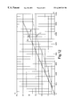
- FIG. 12 is a graphical illustration of the results of a comparative test, comparing use of an assembly in which the pad periphery is unconstrained with an assembly in which the pad is constrained.
- a first embodiment will now be described with reference to an actuator in which it is required to measure thrust in two directions at 180° to each other i.e. both directions along a shaft.
- the electric motor 1 rotates a worm shaft 2 on which is machined a worm 3 meshing with the a wheel 4 which surrounds the output shaft 5 of the actuator.
- the worm wheel 4 can be clutched to the output shaft 5 by means of a sliding dog clutch which is not illustrated in FIG. 1 .
- the actuator When the actuator is operated the external load generates a reacting torque on the worm wheel 4 which, in turn, becomes an axial force on the worm shaft 2 , the force being transmitted via the worm/worm wheel meshing teeth 6 .
- the worm shaft axial force vector may be present in either direction, depending upon the direction of rotation of the worm wheel 4 .
- a pair of deep groove ball bearings 7 and 8 are provided on the worm shaft 2 ; these act as combined journal and thrust bearings.
- Bearing 7 is mounted in a recess in the actuator housing 9 the outer track ring 10 being a free fit in the recess.
- the bearing is located axially in the recess by an abutment between the outer track ring 10 and the mounting plate 11 .
- Bearing 8 is contained within a recess in the backing plate 12 .
- the inner track ring 13 of bearing 8 forms an abutment with the sleeve 14 which is fixed to the worm shaft by the pin 15 .
- the mounting plate 11 and the backing plate 12 Sandwiched between the mounting plate 11 and the backing plate 12 are two resilient polymer discs 16 and 17 . These are on the same pitch circle diameter and mounted 180 degrees apart. The discs are attached to the backing plate 12 and one disc 17 is arranged to be placed over the sensitive face of an electronic pressure transducer 18 positioned in a recess in the mounting plate 11 . The flying leads are arranged to pass out from the rear of the mounting plate via the hole 20 .
- the transducer will preferably be of the type employing a strain gauge or a piezoresistive sensing element arranged in a normal Whetstone Bridge network with a compensating thermo-resistor, the associated circuit being arranged so that the voltage output from the transducer will have a linear, or near linear relationship with the pressure applied to the transducer sensitive face.
- any suitable pressure sensing device capable of detecting pressure changes at its face can be employed.
- the direction of the axial force will be as indicated by the arrow 21 .
- the axial force will be transmitted by the bearing 8 to the backing plate 12 and hence to the resilient polymer members 16 and 17 .
- the pressure generated in these disc shaped members will be the axial force divided by the combined area of the two discs in contact with the backing plate.
- the disc 17 will transmit this pressure to the sensitive face of the transducer 18 so providing a signal which is substantially proportional to the axial force in the shaft 2 .
- the bearing 7 will now be transmitting the axial force in the shaft 2 via the abutment 22 .
- the static outer track ring of the bearing 7 transmits the force via the abutment 23 to the mounting plate 11 .
- the force is now transmitted to the backing plate 12 via the resilient polymer members 16 and 17 . In this mode the backing plate is restrained from axial and rotational movement by three tension shoulder bolts 24 only one of which is shown.
- the thrust bearing assembly is so designed that axial thrust in either direction on the shaft 2 will cause a compressive pressure to be generated in the resilient polymer members 16 and 17 , so providing a force-related signal to be produced from the single transducer 18 .
- the linear relationship numerical factor by which the value of the electrical signal, for example a voltage signal, is multiplied to obtain the pressure reading is termed the transducer constant. It is possible to use this simplified relationship because the transducer characteristic curve between the applied pressure and the voltage reading is, substantially, a straight line passing through, or close to the origin. However, it is within the scope of this invention to encompass other non-linear relationships in which cases a table or chart may be provided in order to derive the applied pressure value from the voltage reading, or, alternatively, the said table or chart may be incorporated into a computer programme.
- the resilient polymer members 16 and 17 have been augmented by two additional groups of resilient polymer discs 25 and 26 in order to increase the area acted upon by the axial forces in the shaft 2 .
- the assembly is still provided with a single pressure transducer in contact with the resilient polymer member 17 .
- the resilient polymer members in order to enable a quick and simple change to the area of the resilient polymer members to be made, it may be more convenient to have the resilient polymer members attached to a separate thin plate 31 , the plate being inserted between the backing plate 12 and the mounting plate 11 .
- the actuator may then be supplied with a set of alternative resilient polymer members already attached to plates 31 so that a rapid field change can be made.
- the pads can be made from any suitable material as selected by the materials specialist such as, for example, silicone rubber having hardness on the IRHD scale between 25 and 60.
- the pads can, of course, be made of any natural or synthetic resilient polymer material provided that the compressive stress range used does not induce creep in the pads and that the physical properties remain substantially constant over the environmental temperature range.
- the pad is most preferably a laminated resilient polymer pad formed with a pair of outer resilient polymer layers that are suitably rubber or another elastomeric material sandwiching between them an intervening layer of a plastics sheet which may be nylon, for example, which has higher modulus of elasticity properties than the resilient material.
- the pad may, for example, comprise resilient layers that are cut out from 0.75 mm thick silicone rubber sheet and the intervening sheet may be 0.25 mm thick nylon. This laminated construction reduces the spread of the pads against the compressing surfaces in use.
- the pad may be made of a homogeneous polymer material.
- FIG. 5 shows the pressure transducer 18 inserted into the thrust bearing assembly surrounding the actuator output shaft 5 and designed to measure the axial force existing in either direction in the output shaft.
- the heavier forces sustained by the output shaft require that the ball thrust bearings 28 and 29 are used in place of the combined journal and thrust bearings 7 and 8 shown in FIG. 1 .
- FIG. 6 shows a single annular shaped resilient polymer member 27 fitted in place of the individual disc shaped members 16 , 17 , 25 and 26 illustrated in FIGS. 1, 2 and 3 .
- This is in order to obtain the maximum possible resilient surface area and may be needed, typically, on an actuator output shaft where the axial forces are considerably higher than those existing on the worm shaft.
- the maximum size of the annular shaped polymer member is 80 mm outside diameter and 45 mm inside diameter, this will provide an area of 3436 mm 2 . At 10 bar transducer reading this will indicate an axial force of 3436N.
- the mid-range signal of the transducer can be extended to indicate a force range from 226N to 3436N, a ratio of approximately 15:1.
- the resilient polymer discs when used in numbers greater than two have been kept to the same diameter and thickness as the disc 17 placed over the transducer 18 . This is to ensure that the discs are all subjected to the same pressure so that the single transducer pressure reading multiplied by the total sum of the disc areas represents the axial force on the shaft. It is possible, however, to use individual resilient polymer members of different shapes with peripheries unconstrained in an assembly provided that certain constraints are used which take account of the fact that, in polymer technology, the compressive modulus is a function of both the nature of the material and the relationship of the areas of the free surfaces and the constrained or contact surfaces of the polymer block being stressed. This relationship is described, for example, in the text book “Engineering with Polymers” by Peter C. Powell and published by Chapman and Hall.
- Strain is defined as the ratio of the deflection of each pad divided by the unstressed thickness i.e. the ratio ⁇ t/t as illustrated in FIG. 7 .
- the absolute modulus in tension or compression is a function of the hardness and is usually denoted by “E 0 ”.
- E 0 the relationship between the apparent modulus “E” and “E 0 ” can be determined by the equation:
- k is an empirical constant having a value between 0.5 and 1.0 and related to the material hardness.
- S is called the Shape Factor and is a dimensionless quantity defined as the ratio of the area of one loaded face of the block divided by the total of the force free areas of the block i.e. those faces which are free to bulge out under load.
- S is squared in the foregoing equation so it is important to ensure that this ratio remains constant for ail the individual blocks in one assembly in order that the apparent modulus term “E” remains constant.
- an actuator of the type in question, will normally be supplied with a force measuring transducer fitted to the worm shaft, as in FIG. 1 for measuring torque on the output shaft, or fitted to the output shaft to measure output shaft axial force as in FIG. 5 .
- a force measuring transducer fitted to the worm shaft, as in FIG. 1 for measuring torque on the output shaft, or fitted to the output shaft to measure output shaft axial force as in FIG. 5 .
- FIG. 8 which shows the end of a typical actuator motor shaft, this illustrates a single resilient polymer disc incorporated between a mounting plate 34 and the housing 35 .
- the resilient polymer disc 17 can be bonded to the plate 34 and the pressure transducer 18 is then mounted into a recess at the end of the motor housing 35 .
- FIG. 9 illustrates a heavier duty application where the thrust is contained by a combined journal and thrust deep groove ball bearing 36 .
- the outer track ring of this bearing is made a free sliding fit in the recess in the motor housing 37 and abuts a plate 38 which is also a free sliding fit in the same recess.
- the resilient polymer disc 17 is bonded to the plate 38 and the pressure transducer 18 is mounted as before into the smaller recess at the end of the motor housing 37 .
- FIG. 10 The essential operating feature of the two directional shaft thrust measuring assemblies, as described and illustrated in FIG. 1 and FIG. 5, is shown in simplified form in FIG. 10 in which the alternative directions of the thrust on the shaft 38 are denoted by arrows 39 and 40 .
- the reacting force is transmitted, via the abutment 41 , between the shaft and the thrust washer 42 and thence, via the thrust washer face 43 to the plate 44 which is free to slide axially in the recess in the housing 45 .
- the force is transmitted by the two resilient polymer discs 16 and 17 which are fixed to the plate 44 and thence to the mounting plate 46 containing the single pressure transducer 18 co-operating with the resilient polymer disc 17 .
- the mounting plate 46 is also a free slidina fit in the housing 45 and the force is finally transmitted to the housing via the abutment 47 .
- the pressure transducer 18 will give a reading proportional to thrust when the thrust is acting in either direction as indicated by the arrows 39 and 40 .
- FIG. 11 shows an embodiment in which a single annular shaped resilient polymer member 54 is sandwiched between the plates 55 and 56 .
- plates correspond in position and operation to the mounting plate 11 and backing plate 12 in FIG. 1 but plate 56 is provided with a recessed annular surface 57 onto which the annular shaped resilient polymer member, or elastomeric pad, 54 is mounted.
- the inner and outer annular wails of the recess form a close fit with the inner and outer circular walls of the polymer member.
- the recess annular wails are extended to provide a sliding fit on cooperating diameters on plate 55 .
- the polymer member is provided with close fitting holes through which pass the tension shoulder bolts 24 .
- This particular embodiment enables a homogeneous silicone rubber pad to be used with no danger of the pad suffering a permanent area change due to creep phenomenon as may occur with the polymer pad having an unsupported edge.
- the effective area of the annular shaped resilient polymer member 54 can be altered by changing the inner and outer diameters and making corresponding changes to the cooperating diameters of plates 55 and 56 so that the pressure range transmitted by the polymer member can be held within the working pressure range of the transducer.
- the recesses may be adjustable in size having adjustable side walls that may be moved together or apart.
- FIG. 12 provides a graph illustrating the surprising substantial benefits of constraining the pad periphery.
- line C on the graph when 3 circular silicone pads of 2 mm thickness and 19 mm diameter were subjected to increasing compression in a first thrust sensor assembly in which the peripheries of the pads were unconstrained the correspondence in the reading from the piezo-resistive pressure sensor (Y-axis 0-60 mV) with increase in applied compressive load (X-axis 0-1,600 N) as shown in line C deviated markedly from the expected (line A).
- line B closely matched the expected (line A).
Landscapes
- Engineering & Computer Science (AREA)
- General Engineering & Computer Science (AREA)
- Physics & Mathematics (AREA)
- Chemical & Material Sciences (AREA)
- General Physics & Mathematics (AREA)
- Mechanical Engineering (AREA)
- Combustion & Propulsion (AREA)
- Analytical Chemistry (AREA)
- Power Engineering (AREA)
- Force Measurement Appropriate To Specific Purposes (AREA)
- Glass Compositions (AREA)
- Mechanical Operated Clutches (AREA)
- Compressors, Vaccum Pumps And Other Relevant Systems (AREA)
- Electrically Driven Valve-Operating Means (AREA)
- Indication Of The Valve Opening Or Closing Status (AREA)
- Ultra Sonic Daignosis Equipment (AREA)
- Electrophonic Musical Instruments (AREA)
- Ignition Installations For Internal Combustion Engines (AREA)
Applications Claiming Priority (5)
| Application Number | Priority Date | Filing Date | Title |
|---|---|---|---|
| GBGB9716158.2A GB9716158D0 (en) | 1997-08-01 | 1997-08-01 | Improved thrust sensors |
| GB9716158 | 1997-08-01 | ||
| GB9808336A GB2327763B (en) | 1997-08-01 | 1998-04-20 | Improved thrust sensors |
| GB9808336 | 1998-04-20 | ||
| PCT/GB1998/002270 WO1999006808A1 (en) | 1997-08-01 | 1998-07-29 | Thrust sensor |
Publications (1)
| Publication Number | Publication Date |
|---|---|
| US6289749B1 true US6289749B1 (en) | 2001-09-18 |
Family
ID=26311970
Family Applications (1)
| Application Number | Title | Priority Date | Filing Date |
|---|---|---|---|
| US09/485,009 Expired - Lifetime US6289749B1 (en) | 1997-08-01 | 1998-07-29 | Thrust sensor assembly |
Country Status (9)
| Country | Link |
|---|---|
| US (1) | US6289749B1 (de) |
| EP (1) | EP1007925B1 (de) |
| JP (1) | JP4176956B2 (de) |
| AT (1) | ATE225499T1 (de) |
| AU (1) | AU8550498A (de) |
| DE (1) | DE69808496T2 (de) |
| GB (1) | GB2327763B (de) |
| NO (1) | NO321290B1 (de) |
| WO (1) | WO1999006808A1 (de) |
Cited By (36)
| Publication number | Priority date | Publication date | Assignee | Title |
|---|---|---|---|---|
| US20070266798A1 (en) * | 2004-11-12 | 2007-11-22 | Phillips Kiln Services Ltd. | Method and Apparatus for Bearing Thrust Monitoring |
| US7469593B2 (en) * | 2006-01-23 | 2008-12-30 | Delphi Technologies, Inc. | Piezo-electric force sensor and method |
| US20090056020A1 (en) * | 2007-08-30 | 2009-03-05 | Jean-Luc Caminade | Pressure detection and measurement sensor incorporating at least one resistive force-detector cell |
| EP2090507A2 (de) | 2008-02-15 | 2009-08-19 | Glacier Bay, Inc. | Antriebssystem |
| US7634948B2 (en) | 2006-12-15 | 2009-12-22 | Prueftechnik Dieter Busch Ag | Process and device for dynamic measurement of the axial deformation of a rotating hollow shaft |
| US20100308846A1 (en) * | 2009-06-05 | 2010-12-09 | Gilles Camus | Pressure sensor comprising a capacitive cell and support device comprising said sensor |
| US20120080622A1 (en) * | 2007-02-16 | 2012-04-05 | Flowserve Management Company | Non-contact torque sensing for valve actuators |
| US8407896B2 (en) | 2008-10-20 | 2013-04-02 | Phillips Kiln Services Ltd. | System and method for setting roller skew |
| US8905895B2 (en) | 2012-06-14 | 2014-12-09 | Emerson Process Management Value Automation, Inc. | Electric motor torque transfer device and sensor |
| US20150129055A1 (en) * | 2013-11-11 | 2015-05-14 | Fresenius Medical Care Holdings, Inc. | Smart Actuator For Valve |
| US20150268110A1 (en) * | 2014-03-24 | 2015-09-24 | Goodrich Actuation Systems Sas | Load sensing system |
| US20150369004A1 (en) * | 2012-09-10 | 2015-12-24 | Onesubsea Ip Uk Limited | Electric Actuator with a Force/Pressure Measurement Sensor |
| US9358331B2 (en) | 2007-09-13 | 2016-06-07 | Fresenius Medical Care Holdings, Inc. | Portable dialysis machine with improved reservoir heating system |
| US9517296B2 (en) | 2007-09-13 | 2016-12-13 | Fresenius Medical Care Holdings, Inc. | Portable dialysis machine |
| US9618136B2 (en) | 2013-09-16 | 2017-04-11 | Fisher Controls International Llc | Rotary valve position indicator |
| EP3085508A4 (de) * | 2013-12-20 | 2017-07-19 | Kabushiki Kaisha Kobe Seiko Sho (Kobe Steel, Ltd.) | Vorrichtung zum messen der auf einen rotor einer versiegelten knetvorrichtung wirkenden axialkraft |
| US9759710B2 (en) | 2008-09-12 | 2017-09-12 | Fresenius Medical Care Holdings, Inc. | Modular reservoir assembly for a hemodialysis and hemofiltration system |
| US10022673B2 (en) | 2007-09-25 | 2018-07-17 | Fresenius Medical Care Holdings, Inc. | Manifolds for use in conducting dialysis |
| US10034973B2 (en) | 2007-11-29 | 2018-07-31 | Fresenius Medical Care Holdings, Inc. | Disposable apparatus and kit for conducting dialysis |
| US10197180B2 (en) | 2009-01-12 | 2019-02-05 | Fresenius Medical Care Holdings, Inc. | Valve system |
| US10258731B2 (en) | 2007-09-13 | 2019-04-16 | Fresenius Medical Care Holdings, Inc. | Manifold diaphragms |
| US10539450B2 (en) | 2012-12-24 | 2020-01-21 | Fresenius Medical Care Holdings, Inc. | Load suspension and weighing system for a dialysis machine reservoir |
| US10670479B2 (en) | 2018-02-27 | 2020-06-02 | Methode Electronics, Inc. | Towing systems and methods using magnetic field sensing |
| US10696109B2 (en) | 2017-03-22 | 2020-06-30 | Methode Electronics Malta Ltd. | Magnetolastic based sensor assembly |
| US10758662B2 (en) | 2007-11-29 | 2020-09-01 | Fresenius Medical Care Holdings, Inc. | Priming system and method for dialysis systems |
| US10758868B2 (en) | 2008-10-30 | 2020-09-01 | Fresenius Medical Care Holdings, Inc. | Methods and systems for leak detection in a dialysis system |
| CN112789430A (zh) * | 2018-10-04 | 2021-05-11 | 运动学有限责任公司 | 力感应式回转驱动器 |
| US11014417B2 (en) | 2018-02-27 | 2021-05-25 | Methode Electronics, Inc. | Towing systems and methods using magnetic field sensing |
| US11084342B2 (en) | 2018-02-27 | 2021-08-10 | Methode Electronics, Inc. | Towing systems and methods using magnetic field sensing |
| US11135882B2 (en) | 2018-02-27 | 2021-10-05 | Methode Electronics, Inc. | Towing systems and methods using magnetic field sensing |
| US11221262B2 (en) | 2018-02-27 | 2022-01-11 | Methode Electronics, Inc. | Towing systems and methods using magnetic field sensing |
| WO2022232636A1 (en) * | 2021-04-30 | 2022-11-03 | Kinematics, Llc | Slew drive systems and methods of use thereof |
| US11491832B2 (en) | 2018-02-27 | 2022-11-08 | Methode Electronics, Inc. | Towing systems and methods using magnetic field sensing |
| US20220373414A1 (en) * | 2020-03-18 | 2022-11-24 | Atlantis Educational Services, Inc. | Load cell assembly |
| US11525798B2 (en) | 2012-12-21 | 2022-12-13 | Fresenius Medical Care Holdings, Inc. | Method and system of monitoring electrolyte levels and composition using capacitance or induction |
| WO2026017332A1 (de) * | 2024-07-19 | 2026-01-22 | Auma Riester Gmbh & Co. Kg | Stellantrieb mit elektromotor |
Families Citing this family (9)
| Publication number | Priority date | Publication date | Assignee | Title |
|---|---|---|---|---|
| JP3411980B2 (ja) | 2000-10-25 | 2003-06-03 | 日本原子力発電株式会社 | 弁装置における異常診断及び劣化予測方法並びに装置 |
| US7021159B2 (en) * | 2002-09-30 | 2006-04-04 | The Gates Corporation | Transducer |
| JP2011080586A (ja) * | 2009-09-10 | 2011-04-21 | Akebono Brake Ind Co Ltd | 電動式ディスクブレーキ |
| JP5870118B2 (ja) * | 2011-12-27 | 2016-02-24 | 大豊工業株式会社 | 弁装置 |
| JP6013314B2 (ja) * | 2013-12-20 | 2016-10-25 | 株式会社神戸製鋼所 | 密閉式混練装置のスラスト荷重計測装置の校正方法 |
| CN108036889B (zh) * | 2017-12-29 | 2023-11-24 | 深圳市奥酷曼智能技术有限公司 | 端面接触力矩传感器及电动助力车 |
| DE102019118269A1 (de) * | 2019-07-05 | 2021-01-07 | Auma Riester Gmbh & Co. Kg | Getriebe und Verwendung einer Messvorrichtung |
| JP7275989B2 (ja) * | 2019-08-13 | 2023-05-18 | 株式会社椿本チエイン | 負荷荷重検出ユニット |
| DE102024106236B4 (de) | 2024-03-05 | 2026-05-21 | Schaeffler Technologies AG & Co. KG | Lageranordnung, Windkraftanlage und Verfahren zur Einstellung einer Lageranordnung |
Citations (10)
| Publication number | Priority date | Publication date | Assignee | Title |
|---|---|---|---|---|
| US4182168A (en) * | 1978-08-31 | 1980-01-08 | Comptrol, Inc. | Thrust-torque transducer |
| US4856327A (en) * | 1988-01-19 | 1989-08-15 | General Physics Corporation | Method and apparatus for monitoring and measuring dynamic loads in thrust inducing systems |
| US4898362A (en) * | 1989-01-31 | 1990-02-06 | Liberty Technology Center, Inc. | Thrust actuated control for motor operated valve |
| EP0363785A2 (de) | 1988-10-12 | 1990-04-18 | POLYSENS S.p.A. | Wandler zur dynamischen Kraftdetektion, Anordnung zur Messung und/oder Kontrolle und Verfahren zu ihrer Anwendung |
| US5036714A (en) * | 1988-12-14 | 1991-08-06 | Wabco Fahrzeughremsen Gmbh | Coupling device for controlling axial thrust forces |
| DE4239947C1 (de) | 1992-11-27 | 1993-11-04 | Riester Kg Werner | Antriebseinheit zur steuerung und regelung von armaturen o. dgl. |
| EP0668491A2 (de) | 1994-02-16 | 1995-08-23 | The Timken Company | Lagereinstellung unter Verwendung eines Druckkraftsensors |
| US5527194A (en) * | 1994-02-02 | 1996-06-18 | Brunswick Corporation | Thrust sensor for marine drives |
| EP0730114A1 (de) | 1993-11-19 | 1996-09-04 | Nippon Gear Co., Ltd. | Vorrichtung zur kontinuierlichen feststellung von überlast in einer betätigungsvorrichtung eines elektrischen ventils |
| US6105439A (en) * | 1997-11-20 | 2000-08-22 | Societe Hispano Suiza | Device for measuring the axial thrust on a rotating shaft |
Family Cites Families (2)
| Publication number | Priority date | Publication date | Assignee | Title |
|---|---|---|---|---|
| DE3146494C2 (de) * | 1981-11-24 | 1986-10-30 | Black & Decker, Inc. (Eine Gesellschaft N.D.Ges.D. Staates Delaware), Newark, Del. | Elektrowerkzeug, insbesondere Handwerkzeug, mit Drehmomentüberwachung |
| JPH01222851A (ja) * | 1988-03-03 | 1989-09-06 | Kitamura Mach Co Ltd | 工作機械の主軸スラストカの検出方法 |
-
1998
- 1998-04-20 GB GB9808336A patent/GB2327763B/en not_active Expired - Lifetime
- 1998-07-29 JP JP2000505494A patent/JP4176956B2/ja not_active Expired - Lifetime
- 1998-07-29 US US09/485,009 patent/US6289749B1/en not_active Expired - Lifetime
- 1998-07-29 AU AU85504/98A patent/AU8550498A/en not_active Abandoned
- 1998-07-29 EP EP98936537A patent/EP1007925B1/de not_active Expired - Lifetime
- 1998-07-29 AT AT98936537T patent/ATE225499T1/de not_active IP Right Cessation
- 1998-07-29 DE DE69808496T patent/DE69808496T2/de not_active Expired - Lifetime
- 1998-07-29 WO PCT/GB1998/002270 patent/WO1999006808A1/en not_active Ceased
-
2000
- 2000-02-01 NO NO20000524A patent/NO321290B1/no not_active IP Right Cessation
Patent Citations (10)
| Publication number | Priority date | Publication date | Assignee | Title |
|---|---|---|---|---|
| US4182168A (en) * | 1978-08-31 | 1980-01-08 | Comptrol, Inc. | Thrust-torque transducer |
| US4856327A (en) * | 1988-01-19 | 1989-08-15 | General Physics Corporation | Method and apparatus for monitoring and measuring dynamic loads in thrust inducing systems |
| EP0363785A2 (de) | 1988-10-12 | 1990-04-18 | POLYSENS S.p.A. | Wandler zur dynamischen Kraftdetektion, Anordnung zur Messung und/oder Kontrolle und Verfahren zu ihrer Anwendung |
| US5036714A (en) * | 1988-12-14 | 1991-08-06 | Wabco Fahrzeughremsen Gmbh | Coupling device for controlling axial thrust forces |
| US4898362A (en) * | 1989-01-31 | 1990-02-06 | Liberty Technology Center, Inc. | Thrust actuated control for motor operated valve |
| DE4239947C1 (de) | 1992-11-27 | 1993-11-04 | Riester Kg Werner | Antriebseinheit zur steuerung und regelung von armaturen o. dgl. |
| EP0730114A1 (de) | 1993-11-19 | 1996-09-04 | Nippon Gear Co., Ltd. | Vorrichtung zur kontinuierlichen feststellung von überlast in einer betätigungsvorrichtung eines elektrischen ventils |
| US5527194A (en) * | 1994-02-02 | 1996-06-18 | Brunswick Corporation | Thrust sensor for marine drives |
| EP0668491A2 (de) | 1994-02-16 | 1995-08-23 | The Timken Company | Lagereinstellung unter Verwendung eines Druckkraftsensors |
| US6105439A (en) * | 1997-11-20 | 2000-08-22 | Societe Hispano Suiza | Device for measuring the axial thrust on a rotating shaft |
Cited By (66)
| Publication number | Priority date | Publication date | Assignee | Title |
|---|---|---|---|---|
| US8485052B2 (en) | 2004-11-12 | 2013-07-16 | Flsmidth Sioux City, Inc. | Method and apparatus for bearing thrust monitoring |
| US20070266798A1 (en) * | 2004-11-12 | 2007-11-22 | Phillips Kiln Services Ltd. | Method and Apparatus for Bearing Thrust Monitoring |
| US7997153B2 (en) | 2004-11-12 | 2011-08-16 | Phillips Kiln Services Ltd. | Method and apparatus for bearing thrust monitoring |
| US20110197420A1 (en) * | 2004-11-12 | 2011-08-18 | Phillips Kiln Services, Ltd. | Method and Apparatus for Bearing Thrust Monitoring |
| US7469593B2 (en) * | 2006-01-23 | 2008-12-30 | Delphi Technologies, Inc. | Piezo-electric force sensor and method |
| US7634948B2 (en) | 2006-12-15 | 2009-12-22 | Prueftechnik Dieter Busch Ag | Process and device for dynamic measurement of the axial deformation of a rotating hollow shaft |
| US9500542B2 (en) | 2007-02-16 | 2016-11-22 | Flowserve Management Company | Non-contact torque sensing for valve actuators |
| US8608128B2 (en) * | 2007-02-16 | 2013-12-17 | Flowserve Management Company | Non-contact torque sensing for valve actuators |
| US20120080622A1 (en) * | 2007-02-16 | 2012-04-05 | Flowserve Management Company | Non-contact torque sensing for valve actuators |
| US20090056020A1 (en) * | 2007-08-30 | 2009-03-05 | Jean-Luc Caminade | Pressure detection and measurement sensor incorporating at least one resistive force-detector cell |
| US7752926B2 (en) * | 2007-08-30 | 2010-07-13 | Hill-Rom Industries, SA | Pressure detection and measurement sensor incorporating at least one resistive force-detector cell |
| US9358331B2 (en) | 2007-09-13 | 2016-06-07 | Fresenius Medical Care Holdings, Inc. | Portable dialysis machine with improved reservoir heating system |
| US9517296B2 (en) | 2007-09-13 | 2016-12-13 | Fresenius Medical Care Holdings, Inc. | Portable dialysis machine |
| US11071811B2 (en) | 2007-09-13 | 2021-07-27 | Fresenius Medical Care Holdings, Inc. | Portable dialysis machine |
| US10596310B2 (en) | 2007-09-13 | 2020-03-24 | Fresenius Medical Care Holdings, Inc. | Portable dialysis machine |
| US10383993B2 (en) | 2007-09-13 | 2019-08-20 | Fresenius Medical Care Holdings, Inc. | Pump shoe for use in a pumping system of a dialysis machine |
| US10258731B2 (en) | 2007-09-13 | 2019-04-16 | Fresenius Medical Care Holdings, Inc. | Manifold diaphragms |
| US11318248B2 (en) | 2007-09-13 | 2022-05-03 | Fresenius Medical Care Holdings, Inc. | Methods for heating a reservoir unit in a dialysis system |
| US10857281B2 (en) | 2007-09-13 | 2020-12-08 | Fresenius Medical Care Holdings, Inc. | Disposable kits adapted for use in a dialysis machine |
| US10022673B2 (en) | 2007-09-25 | 2018-07-17 | Fresenius Medical Care Holdings, Inc. | Manifolds for use in conducting dialysis |
| US11224841B2 (en) | 2007-09-25 | 2022-01-18 | Fresenius Medical Care Holdings, Inc. | Integrated disposable component system for use in dialysis systems |
| US11439738B2 (en) | 2007-11-29 | 2022-09-13 | Fresenius Medical Care Holdings, Inc. | Methods and Systems for fluid balancing in a dialysis system |
| US10758661B2 (en) | 2007-11-29 | 2020-09-01 | Fresenius Medical Care Holdings, Inc. | Disposable apparatus and kit for conducting dialysis |
| US10034973B2 (en) | 2007-11-29 | 2018-07-31 | Fresenius Medical Care Holdings, Inc. | Disposable apparatus and kit for conducting dialysis |
| US10758662B2 (en) | 2007-11-29 | 2020-09-01 | Fresenius Medical Care Holdings, Inc. | Priming system and method for dialysis systems |
| US20090222155A1 (en) * | 2008-02-15 | 2009-09-03 | Glacier Bay, Inc. | Propulsion system |
| EP2090507A2 (de) | 2008-02-15 | 2009-08-19 | Glacier Bay, Inc. | Antriebssystem |
| US9759710B2 (en) | 2008-09-12 | 2017-09-12 | Fresenius Medical Care Holdings, Inc. | Modular reservoir assembly for a hemodialysis and hemofiltration system |
| US8407896B2 (en) | 2008-10-20 | 2013-04-02 | Phillips Kiln Services Ltd. | System and method for setting roller skew |
| US10758868B2 (en) | 2008-10-30 | 2020-09-01 | Fresenius Medical Care Holdings, Inc. | Methods and systems for leak detection in a dialysis system |
| US10670577B2 (en) | 2008-10-30 | 2020-06-02 | Fresenius Medical Care Holdings, Inc. | Modular reservoir assembly for a hemodialysis and hemofiltration system |
| US11169137B2 (en) | 2008-10-30 | 2021-11-09 | Fresenius Medical Care Holdings, Inc. | Modular reservoir assembly for a hemodialysis and hemofiltration system |
| US10808861B2 (en) | 2009-01-12 | 2020-10-20 | Fresenius Medical Care Holdings, Inc. | Valve system |
| US10197180B2 (en) | 2009-01-12 | 2019-02-05 | Fresenius Medical Care Holdings, Inc. | Valve system |
| US8598893B2 (en) | 2009-06-05 | 2013-12-03 | Hill-Rom Industries Sa | Pressure sensor comprising a capacitive cell and support device comprising said sensor |
| US20100308846A1 (en) * | 2009-06-05 | 2010-12-09 | Gilles Camus | Pressure sensor comprising a capacitive cell and support device comprising said sensor |
| US8905895B2 (en) | 2012-06-14 | 2014-12-09 | Emerson Process Management Value Automation, Inc. | Electric motor torque transfer device and sensor |
| US20150369004A1 (en) * | 2012-09-10 | 2015-12-24 | Onesubsea Ip Uk Limited | Electric Actuator with a Force/Pressure Measurement Sensor |
| US11525798B2 (en) | 2012-12-21 | 2022-12-13 | Fresenius Medical Care Holdings, Inc. | Method and system of monitoring electrolyte levels and composition using capacitance or induction |
| US10539450B2 (en) | 2012-12-24 | 2020-01-21 | Fresenius Medical Care Holdings, Inc. | Load suspension and weighing system for a dialysis machine reservoir |
| US11187572B2 (en) | 2012-12-24 | 2021-11-30 | Fresenius Medical Care Holdings, Inc. | Dialysis systems with a suspended reservoir |
| US9618136B2 (en) | 2013-09-16 | 2017-04-11 | Fisher Controls International Llc | Rotary valve position indicator |
| US20150129055A1 (en) * | 2013-11-11 | 2015-05-14 | Fresenius Medical Care Holdings, Inc. | Smart Actuator For Valve |
| US10019020B2 (en) | 2013-11-11 | 2018-07-10 | Fresenius Medical Care Holdings, Inc. | Smart actuator for valve |
| US9354640B2 (en) * | 2013-11-11 | 2016-05-31 | Fresenius Medical Care Holdings, Inc. | Smart actuator for valve |
| US10817004B2 (en) | 2013-11-11 | 2020-10-27 | Fresenius Medical Care Holdings, Inc. | Valve system with a pressure sensing displacement member |
| EP3085508A4 (de) * | 2013-12-20 | 2017-07-19 | Kabushiki Kaisha Kobe Seiko Sho (Kobe Steel, Ltd.) | Vorrichtung zum messen der auf einen rotor einer versiegelten knetvorrichtung wirkenden axialkraft |
| US20150268110A1 (en) * | 2014-03-24 | 2015-09-24 | Goodrich Actuation Systems Sas | Load sensing system |
| US9891122B2 (en) * | 2014-03-24 | 2018-02-13 | Goodrich Actuation Systems Sas | Load sensing system |
| US10940726B2 (en) | 2017-03-22 | 2021-03-09 | Methode Electronics Malta Ltd. | Magnetoelastic based sensor assembly |
| US10696109B2 (en) | 2017-03-22 | 2020-06-30 | Methode Electronics Malta Ltd. | Magnetolastic based sensor assembly |
| US11084342B2 (en) | 2018-02-27 | 2021-08-10 | Methode Electronics, Inc. | Towing systems and methods using magnetic field sensing |
| US11491832B2 (en) | 2018-02-27 | 2022-11-08 | Methode Electronics, Inc. | Towing systems and methods using magnetic field sensing |
| US10670479B2 (en) | 2018-02-27 | 2020-06-02 | Methode Electronics, Inc. | Towing systems and methods using magnetic field sensing |
| US11135882B2 (en) | 2018-02-27 | 2021-10-05 | Methode Electronics, Inc. | Towing systems and methods using magnetic field sensing |
| US11221262B2 (en) | 2018-02-27 | 2022-01-11 | Methode Electronics, Inc. | Towing systems and methods using magnetic field sensing |
| US11014417B2 (en) | 2018-02-27 | 2021-05-25 | Methode Electronics, Inc. | Towing systems and methods using magnetic field sensing |
| CN112789430A (zh) * | 2018-10-04 | 2021-05-11 | 运动学有限责任公司 | 力感应式回转驱动器 |
| EP3861231A4 (de) * | 2018-10-04 | 2022-06-22 | Kinematics, LLC | Kraftmessender schwenkantrieb |
| US11644084B2 (en) | 2018-10-04 | 2023-05-09 | Kinematics, Llc | Force sensing slew drive |
| US20220373414A1 (en) * | 2020-03-18 | 2022-11-24 | Atlantis Educational Services, Inc. | Load cell assembly |
| US12055456B2 (en) * | 2020-03-18 | 2024-08-06 | Atlantis Educational Services, Inc. | Load cell assembly |
| US20220349462A1 (en) * | 2021-04-30 | 2022-11-03 | Kinematics, Llc | Slew drive systems and methods of use thereof |
| WO2022232636A1 (en) * | 2021-04-30 | 2022-11-03 | Kinematics, Llc | Slew drive systems and methods of use thereof |
| US12253157B2 (en) * | 2021-04-30 | 2025-03-18 | Kinematics, Llc | Systems and methods of use of slew drivers with sensor carriers |
| WO2026017332A1 (de) * | 2024-07-19 | 2026-01-22 | Auma Riester Gmbh & Co. Kg | Stellantrieb mit elektromotor |
Also Published As
| Publication number | Publication date |
|---|---|
| JP4176956B2 (ja) | 2008-11-05 |
| NO20000524L (no) | 2000-02-01 |
| DE69808496T2 (de) | 2003-07-10 |
| JP2001512233A (ja) | 2001-08-21 |
| WO1999006808A1 (en) | 1999-02-11 |
| EP1007925B1 (de) | 2002-10-02 |
| AU8550498A (en) | 1999-02-22 |
| GB2327763A (en) | 1999-02-03 |
| DE69808496D1 (de) | 2002-11-07 |
| ATE225499T1 (de) | 2002-10-15 |
| GB2327763B (en) | 1999-06-23 |
| GB9808336D0 (en) | 1998-06-17 |
| NO20000524D0 (no) | 2000-02-01 |
| EP1007925A1 (de) | 2000-06-14 |
| NO321290B1 (no) | 2006-04-18 |
Similar Documents
| Publication | Publication Date | Title |
|---|---|---|
| EP1007925B1 (de) | Schubsensor | |
| US6240789B1 (en) | Permanently instrumented actuated valve assembly, with internally-gauged, permanently instrumented shaft | |
| US8714024B2 (en) | Load measurement method and device | |
| US5503045A (en) | Drive assembly for controlling a powered device | |
| AU2008247581B2 (en) | Torque arm assembly for a backstopping clutch | |
| US12326176B2 (en) | Ball screw assembly with integral force measurement | |
| US20090266652A1 (en) | Brake force transducer for electric brakes | |
| KR102065572B1 (ko) | 기어박스 토크 측정 시스템 | |
| DK1644706T3 (en) | Cross Spring element | |
| JP7015258B2 (ja) | 電動弁駆動部の状態監視装置および状態監視方法 | |
| FI3724540T3 (fi) | Dynaaminen tiiviste ja pyörivä läpivienti, jossa on tällainen dynaaminen tiiviste | |
| US20220176526A1 (en) | Torque screwdriver arrangement and method for operating such a torque screwdriver arrangement | |
| CN101443565A (zh) | 轴承失效指示器 | |
| TWI912523B (zh) | 諧波齒輪裝置及致動器 | |
| CA1319838C (en) | Pressure transducer | |
| GB2256050A (en) | Transducer using hall effect sensor | |
| US2718782A (en) | Torque indicator | |
| JP2022541532A (ja) | 一体の間隙付きケーシングおよびセンサモジュールを備えた制動装置および/または緊締装置 | |
| US3668926A (en) | Apparatus for indicating torque applied to pipe rotated by a rotary table | |
| RU1774196C (ru) | Устройство дл измерени крут щего момента | |
| CN103123288B (zh) | 载荷测量方法和装置 | |
| GB9302014D0 (en) | Strain measuring device | |
| US5711153A (en) | Precision hydraulic adjustable stop | |
| JPS61240133A (ja) | トルク検出装置 | |
| JPH0775816B2 (ja) | 軸力測定装置 |
Legal Events
| Date | Code | Title | Description |
|---|---|---|---|
| AS | Assignment |
Owner name: ROTORK CONTROLS LIMITED, ENGLAND Free format text: ASSIGNMENT OF ASSIGNORS INTEREST;ASSIGNOR:SANDERS, PETER;REEL/FRAME:010636/0184 Effective date: 20000114 |
|
| STCF | Information on status: patent grant |
Free format text: PATENTED CASE |
|
| FPAY | Fee payment |
Year of fee payment: 4 |
|
| FEPP | Fee payment procedure |
Free format text: PAYER NUMBER DE-ASSIGNED (ORIGINAL EVENT CODE: RMPN); ENTITY STATUS OF PATENT OWNER: LARGE ENTITY Free format text: PAYOR NUMBER ASSIGNED (ORIGINAL EVENT CODE: ASPN); ENTITY STATUS OF PATENT OWNER: LARGE ENTITY |
|
| FPAY | Fee payment |
Year of fee payment: 8 |
|
| FPAY | Fee payment |
Year of fee payment: 12 |
|
| FEPP | Fee payment procedure |
Free format text: PAYOR NUMBER ASSIGNED (ORIGINAL EVENT CODE: ASPN); ENTITY STATUS OF PATENT OWNER: LARGE ENTITY Free format text: PAYER NUMBER DE-ASSIGNED (ORIGINAL EVENT CODE: RMPN); ENTITY STATUS OF PATENT OWNER: LARGE ENTITY |