US6355123B1 - Roll-over air bag having a reinforced perimeter seal and associated method for producing a flat reinforced seal in a roll-over air bag - Google Patents
Roll-over air bag having a reinforced perimeter seal and associated method for producing a flat reinforced seal in a roll-over air bag Download PDFInfo
- Publication number
- US6355123B1 US6355123B1 US09/405,339 US40533999A US6355123B1 US 6355123 B1 US6355123 B1 US 6355123B1 US 40533999 A US40533999 A US 40533999A US 6355123 B1 US6355123 B1 US 6355123B1
- Authority
- US
- United States
- Prior art keywords
- roll
- fabric panel
- airbag
- over
- reinforced
- Prior art date
- Legal status (The legal status is an assumption and is not a legal conclusion. Google has not performed a legal analysis and makes no representation as to the accuracy of the status listed.)
- Expired - Fee Related
Links
Images




Classifications
-
- B—PERFORMING OPERATIONS; TRANSPORTING
- B60—VEHICLES IN GENERAL
- B60R—VEHICLES, VEHICLE FITTINGS, OR VEHICLE PARTS, NOT OTHERWISE PROVIDED FOR
- B60R21/00—Arrangements or fittings on vehicles for protecting or preventing injuries to occupants or pedestrians in case of accidents or other traffic risks
- B60R21/02—Occupant safety arrangements or fittings, e.g. crash pads
- B60R21/16—Inflatable occupant restraints or confinements designed to inflate upon impact or impending impact, e.g. air bags
- B60R21/23—Inflatable members
- B60R21/235—Inflatable members characterised by their material
-
- B—PERFORMING OPERATIONS; TRANSPORTING
- B29—WORKING OF PLASTICS; WORKING OF SUBSTANCES IN A PLASTIC STATE IN GENERAL
- B29C—SHAPING OR JOINING OF PLASTICS; SHAPING OF MATERIAL IN A PLASTIC STATE, NOT OTHERWISE PROVIDED FOR; AFTER-TREATMENT OF THE SHAPED PRODUCTS, e.g. REPAIRING
- B29C65/00—Joining or sealing of preformed parts, e.g. welding of plastics materials; Apparatus therefor
- B29C65/02—Joining or sealing of preformed parts, e.g. welding of plastics materials; Apparatus therefor by heating, with or without pressure
- B29C65/04—Dielectric heating, e.g. high-frequency welding, i.e. radio frequency welding of plastic materials having dielectric properties, e.g. PVC
-
- B—PERFORMING OPERATIONS; TRANSPORTING
- B29—WORKING OF PLASTICS; WORKING OF SUBSTANCES IN A PLASTIC STATE IN GENERAL
- B29C—SHAPING OR JOINING OF PLASTICS; SHAPING OF MATERIAL IN A PLASTIC STATE, NOT OTHERWISE PROVIDED FOR; AFTER-TREATMENT OF THE SHAPED PRODUCTS, e.g. REPAIRING
- B29C66/00—General aspects of processes or apparatus for joining preformed parts
- B29C66/004—Preventing sticking together, e.g. of some areas of the parts to be joined
-
- B—PERFORMING OPERATIONS; TRANSPORTING
- B29—WORKING OF PLASTICS; WORKING OF SUBSTANCES IN A PLASTIC STATE IN GENERAL
- B29C—SHAPING OR JOINING OF PLASTICS; SHAPING OF MATERIAL IN A PLASTIC STATE, NOT OTHERWISE PROVIDED FOR; AFTER-TREATMENT OF THE SHAPED PRODUCTS, e.g. REPAIRING
- B29C66/00—General aspects of processes or apparatus for joining preformed parts
- B29C66/01—General aspects dealing with the joint area or with the area to be joined
- B29C66/05—Particular design of joint configurations
- B29C66/10—Particular design of joint configurations particular design of the joint cross-sections
- B29C66/11—Joint cross-sections comprising a single joint-segment, i.e. one of the parts to be joined comprising a single joint-segment in the joint cross-section
- B29C66/112—Single lapped joints
- B29C66/1122—Single lap to lap joints, i.e. overlap joints
-
- B—PERFORMING OPERATIONS; TRANSPORTING
- B29—WORKING OF PLASTICS; WORKING OF SUBSTANCES IN A PLASTIC STATE IN GENERAL
- B29C—SHAPING OR JOINING OF PLASTICS; SHAPING OF MATERIAL IN A PLASTIC STATE, NOT OTHERWISE PROVIDED FOR; AFTER-TREATMENT OF THE SHAPED PRODUCTS, e.g. REPAIRING
- B29C66/00—General aspects of processes or apparatus for joining preformed parts
- B29C66/01—General aspects dealing with the joint area or with the area to be joined
- B29C66/05—Particular design of joint configurations
- B29C66/10—Particular design of joint configurations particular design of the joint cross-sections
- B29C66/13—Single flanged joints; Fin-type joints; Single hem joints; Edge joints; Interpenetrating fingered joints; Other specific particular designs of joint cross-sections not provided for in groups B29C66/11 - B29C66/12
- B29C66/135—Single hemmed joints, i.e. one of the parts to be joined being hemmed in the joint area
- B29C66/1352—Single hem to hem joints
-
- B—PERFORMING OPERATIONS; TRANSPORTING
- B29—WORKING OF PLASTICS; WORKING OF SUBSTANCES IN A PLASTIC STATE IN GENERAL
- B29C—SHAPING OR JOINING OF PLASTICS; SHAPING OF MATERIAL IN A PLASTIC STATE, NOT OTHERWISE PROVIDED FOR; AFTER-TREATMENT OF THE SHAPED PRODUCTS, e.g. REPAIRING
- B29C66/00—General aspects of processes or apparatus for joining preformed parts
- B29C66/40—General aspects of joining substantially flat articles, e.g. plates, sheets or web-like materials; Making flat seams in tubular or hollow articles; Joining single elements to substantially flat surfaces
- B29C66/41—Joining substantially flat articles ; Making flat seams in tubular or hollow articles
- B29C66/43—Joining a relatively small portion of the surface of said articles
- B29C66/438—Joining sheets for making hollow-walled, channelled structures or multi-tubular articles
-
- B—PERFORMING OPERATIONS; TRANSPORTING
- B60—VEHICLES IN GENERAL
- B60R—VEHICLES, VEHICLE FITTINGS, OR VEHICLE PARTS, NOT OTHERWISE PROVIDED FOR
- B60R21/00—Arrangements or fittings on vehicles for protecting or preventing injuries to occupants or pedestrians in case of accidents or other traffic risks
- B60R21/02—Occupant safety arrangements or fittings, e.g. crash pads
- B60R21/16—Inflatable occupant restraints or confinements designed to inflate upon impact or impending impact, e.g. air bags
- B60R21/23—Inflatable members
- B60R21/231—Inflatable members characterised by their shape, construction or spatial configuration
- B60R21/23138—Inflatable members characterised by their shape, construction or spatial configuration specially adapted for side protection
-
- B—PERFORMING OPERATIONS; TRANSPORTING
- B60—VEHICLES IN GENERAL
- B60R—VEHICLES, VEHICLE FITTINGS, OR VEHICLE PARTS, NOT OTHERWISE PROVIDED FOR
- B60R21/00—Arrangements or fittings on vehicles for protecting or preventing injuries to occupants or pedestrians in case of accidents or other traffic risks
- B60R21/02—Occupant safety arrangements or fittings, e.g. crash pads
- B60R21/16—Inflatable occupant restraints or confinements designed to inflate upon impact or impending impact, e.g. air bags
- B60R21/23—Inflatable members
- B60R21/231—Inflatable members characterised by their shape, construction or spatial configuration
- B60R21/2334—Expansion control features
- B60R21/2338—Tethers
-
- B—PERFORMING OPERATIONS; TRANSPORTING
- B29—WORKING OF PLASTICS; WORKING OF SUBSTANCES IN A PLASTIC STATE IN GENERAL
- B29C—SHAPING OR JOINING OF PLASTICS; SHAPING OF MATERIAL IN A PLASTIC STATE, NOT OTHERWISE PROVIDED FOR; AFTER-TREATMENT OF THE SHAPED PRODUCTS, e.g. REPAIRING
- B29C66/00—General aspects of processes or apparatus for joining preformed parts
- B29C66/70—General aspects of processes or apparatus for joining preformed parts characterised by the composition, physical properties or the structure of the material of the parts to be joined; Joining with non-plastics material
- B29C66/71—General aspects of processes or apparatus for joining preformed parts characterised by the composition, physical properties or the structure of the material of the parts to be joined; Joining with non-plastics material characterised by the composition of the plastics material of the parts to be joined
-
- B—PERFORMING OPERATIONS; TRANSPORTING
- B29—WORKING OF PLASTICS; WORKING OF SUBSTANCES IN A PLASTIC STATE IN GENERAL
- B29C—SHAPING OR JOINING OF PLASTICS; SHAPING OF MATERIAL IN A PLASTIC STATE, NOT OTHERWISE PROVIDED FOR; AFTER-TREATMENT OF THE SHAPED PRODUCTS, e.g. REPAIRING
- B29C66/00—General aspects of processes or apparatus for joining preformed parts
- B29C66/70—General aspects of processes or apparatus for joining preformed parts characterised by the composition, physical properties or the structure of the material of the parts to be joined; Joining with non-plastics material
- B29C66/73—General aspects of processes or apparatus for joining preformed parts characterised by the composition, physical properties or the structure of the material of the parts to be joined; Joining with non-plastics material characterised by the intensive physical properties of the material of the parts to be joined, by the optical properties of the material of the parts to be joined, by the extensive physical properties of the parts to be joined, by the state of the material of the parts to be joined or by the material of the parts to be joined being a thermoplastic or a thermoset
- B29C66/739—General aspects of processes or apparatus for joining preformed parts characterised by the composition, physical properties or the structure of the material of the parts to be joined; Joining with non-plastics material characterised by the intensive physical properties of the material of the parts to be joined, by the optical properties of the material of the parts to be joined, by the extensive physical properties of the parts to be joined, by the state of the material of the parts to be joined or by the material of the parts to be joined being a thermoplastic or a thermoset characterised by the material of the parts to be joined being a thermoplastic or a thermoset
- B29C66/7392—General aspects of processes or apparatus for joining preformed parts characterised by the composition, physical properties or the structure of the material of the parts to be joined; Joining with non-plastics material characterised by the intensive physical properties of the material of the parts to be joined, by the optical properties of the material of the parts to be joined, by the extensive physical properties of the parts to be joined, by the state of the material of the parts to be joined or by the material of the parts to be joined being a thermoplastic or a thermoset characterised by the material of the parts to be joined being a thermoplastic or a thermoset characterised by the material of at least one of the parts being a thermoplastic
-
- B—PERFORMING OPERATIONS; TRANSPORTING
- B29—WORKING OF PLASTICS; WORKING OF SUBSTANCES IN A PLASTIC STATE IN GENERAL
- B29C—SHAPING OR JOINING OF PLASTICS; SHAPING OF MATERIAL IN A PLASTIC STATE, NOT OTHERWISE PROVIDED FOR; AFTER-TREATMENT OF THE SHAPED PRODUCTS, e.g. REPAIRING
- B29C66/00—General aspects of processes or apparatus for joining preformed parts
- B29C66/80—General aspects of machine operations or constructions and parts thereof
- B29C66/83—General aspects of machine operations or constructions and parts thereof characterised by the movement of the joining or pressing tools
- B29C66/832—Reciprocating joining or pressing tools
- B29C66/8322—Joining or pressing tools reciprocating along one axis
-
- B—PERFORMING OPERATIONS; TRANSPORTING
- B29—WORKING OF PLASTICS; WORKING OF SUBSTANCES IN A PLASTIC STATE IN GENERAL
- B29L—INDEXING SCHEME ASSOCIATED WITH SUBCLASS B29C, RELATING TO PARTICULAR ARTICLES
- B29L2031/00—Other particular articles
- B29L2031/703—Bellows
-
- B—PERFORMING OPERATIONS; TRANSPORTING
- B60—VEHICLES IN GENERAL
- B60R—VEHICLES, VEHICLE FITTINGS, OR VEHICLE PARTS, NOT OTHERWISE PROVIDED FOR
- B60R21/00—Arrangements or fittings on vehicles for protecting or preventing injuries to occupants or pedestrians in case of accidents or other traffic risks
- B60R21/02—Occupant safety arrangements or fittings, e.g. crash pads
- B60R21/16—Inflatable occupant restraints or confinements designed to inflate upon impact or impending impact, e.g. air bags
- B60R21/23—Inflatable members
- B60R21/231—Inflatable members characterised by their shape, construction or spatial configuration
- B60R21/233—Inflatable members characterised by their shape, construction or spatial configuration comprising a plurality of individual compartments; comprising two or more bag-like members, one within the other
- B60R2021/23316—Inner seams, e.g. creating separate compartments or used as tethering means
-
- B—PERFORMING OPERATIONS; TRANSPORTING
- B60—VEHICLES IN GENERAL
- B60R—VEHICLES, VEHICLE FITTINGS, OR VEHICLE PARTS, NOT OTHERWISE PROVIDED FOR
- B60R21/00—Arrangements or fittings on vehicles for protecting or preventing injuries to occupants or pedestrians in case of accidents or other traffic risks
- B60R21/02—Occupant safety arrangements or fittings, e.g. crash pads
- B60R21/16—Inflatable occupant restraints or confinements designed to inflate upon impact or impending impact, e.g. air bags
- B60R21/23—Inflatable members
- B60R21/231—Inflatable members characterised by their shape, construction or spatial configuration
- B60R21/2334—Expansion control features
- B60R21/2338—Tethers
- B60R2021/23382—Internal tether means
-
- B—PERFORMING OPERATIONS; TRANSPORTING
- B60—VEHICLES IN GENERAL
- B60R—VEHICLES, VEHICLE FITTINGS, OR VEHICLE PARTS, NOT OTHERWISE PROVIDED FOR
- B60R21/00—Arrangements or fittings on vehicles for protecting or preventing injuries to occupants or pedestrians in case of accidents or other traffic risks
- B60R21/02—Occupant safety arrangements or fittings, e.g. crash pads
- B60R21/16—Inflatable occupant restraints or confinements designed to inflate upon impact or impending impact, e.g. air bags
- B60R21/23—Inflatable members
- B60R21/235—Inflatable members characterised by their material
- B60R2021/23504—Inflatable members characterised by their material characterised by material
- B60R2021/23509—Fabric
- B60R2021/23514—Fabric coated fabric
-
- B—PERFORMING OPERATIONS; TRANSPORTING
- B60—VEHICLES IN GENERAL
- B60R—VEHICLES, VEHICLE FITTINGS, OR VEHICLE PARTS, NOT OTHERWISE PROVIDED FOR
- B60R21/00—Arrangements or fittings on vehicles for protecting or preventing injuries to occupants or pedestrians in case of accidents or other traffic risks
- B60R21/02—Occupant safety arrangements or fittings, e.g. crash pads
- B60R21/16—Inflatable occupant restraints or confinements designed to inflate upon impact or impending impact, e.g. air bags
- B60R21/23—Inflatable members
- B60R21/235—Inflatable members characterised by their material
- B60R2021/23571—Inflatable members characterised by their material characterised by connections between panels
- B60R2021/23576—Sewing
-
- B—PERFORMING OPERATIONS; TRANSPORTING
- B60—VEHICLES IN GENERAL
- B60R—VEHICLES, VEHICLE FITTINGS, OR VEHICLE PARTS, NOT OTHERWISE PROVIDED FOR
- B60R21/00—Arrangements or fittings on vehicles for protecting or preventing injuries to occupants or pedestrians in case of accidents or other traffic risks
- B60R21/02—Occupant safety arrangements or fittings, e.g. crash pads
- B60R21/16—Inflatable occupant restraints or confinements designed to inflate upon impact or impending impact, e.g. air bags
- B60R21/23—Inflatable members
- B60R21/235—Inflatable members characterised by their material
- B60R2021/23571—Inflatable members characterised by their material characterised by connections between panels
- B60R2021/2358—Bonding
-
- B—PERFORMING OPERATIONS; TRANSPORTING
- B60—VEHICLES IN GENERAL
- B60R—VEHICLES, VEHICLE FITTINGS, OR VEHICLE PARTS, NOT OTHERWISE PROVIDED FOR
- B60R21/00—Arrangements or fittings on vehicles for protecting or preventing injuries to occupants or pedestrians in case of accidents or other traffic risks
- B60R21/02—Occupant safety arrangements or fittings, e.g. crash pads
- B60R21/16—Inflatable occupant restraints or confinements designed to inflate upon impact or impending impact, e.g. air bags
- B60R21/23—Inflatable members
- B60R21/235—Inflatable members characterised by their material
- B60R2021/23571—Inflatable members characterised by their material characterised by connections between panels
- B60R2021/2359—Welding
-
- B—PERFORMING OPERATIONS; TRANSPORTING
- B60—VEHICLES IN GENERAL
- B60R—VEHICLES, VEHICLE FITTINGS, OR VEHICLE PARTS, NOT OTHERWISE PROVIDED FOR
- B60R22/00—Safety belts or body harnesses in vehicles
- B60R22/18—Anchoring devices
- B60R2022/1818—Belt guides
-
- B—PERFORMING OPERATIONS; TRANSPORTING
- B60—VEHICLES IN GENERAL
- B60R—VEHICLES, VEHICLE FITTINGS, OR VEHICLE PARTS, NOT OTHERWISE PROVIDED FOR
- B60R21/00—Arrangements or fittings on vehicles for protecting or preventing injuries to occupants or pedestrians in case of accidents or other traffic risks
- B60R21/02—Occupant safety arrangements or fittings, e.g. crash pads
- B60R21/16—Inflatable occupant restraints or confinements designed to inflate upon impact or impending impact, e.g. air bags
- B60R21/23—Inflatable members
- B60R21/231—Inflatable members characterised by their shape, construction or spatial configuration
- B60R21/232—Curtain-type airbags deploying mainly in a vertical direction from their top edge
-
- B—PERFORMING OPERATIONS; TRANSPORTING
- B60—VEHICLES IN GENERAL
- B60R—VEHICLES, VEHICLE FITTINGS, OR VEHICLE PARTS, NOT OTHERWISE PROVIDED FOR
- B60R22/00—Safety belts or body harnesses in vehicles
Definitions
- This invention relates to the field of automotive restraints. More particularly, it relates to a self-inflating restraint for protecting occupants of an automobile in the event of a vehicle roll-over.
- Airbags have been in use for a number of years to protect the front occupants of a vehicle from impacting the steering wheel, dash and/or the windshield during a front impact incident. And, airbags have recently been utilized to protect the occupants striking the side of the vehicle during side-impact and/or roll-over episodes.
- a roll-over air bag due to the nature of a roll-over incident, must maintain air pressure for a pre-determined amount of time in order to provide adequate protection to the vehicle occupant(s) during the roll-over episode.
- This sustained period of inflation under pressure requires a reinforced perimeter not found on typical frontal or side impact airbags.
- roll-over airbags often referred to as “curtains”
- side-impact airbags are typically stored, either in the seat, in the side pillar, or proximate the conjunction of the headliner and the side panel of the vehicle in a deflated, and often folded, condition.
- U.S. Pat. No. 5,529,332 issued to Wipasuramonton on Jun. 25, 1996 and U.S. Pat. No. 5,540,460 issued to Wipasuramonton on Jul. 30, 1996, each disclose a side-impact airbag which is inflatable into a position between a vehicle occupant and the side structure of a vehicle.
- U.S. Pat. No. 5,909,895 issued to lino, et al. discloses a thermoplastic resin film bag.
- the background art section describes a conventional airbag having a reinforced joint face and teaches that the reinforcing cloth is a cylindrical body that is three-dimensionally arranged to a two dimensional join face in which production is troublesome and in which, if joined two-dimensionally, creates a problem with wrinkling the joint face.
- a roll-over self-inflating airbag that has a reinforced perimeter seal that is capable of sustaining the requisite pressure of the airbag for a predetermined period of time, and that is configured to limit the displacement of the sides from one another during expansion.
- a method of producing a reinforced joint, or seam that can be sealed flat, without a problem of wrinkling the joint face, while still providing adequate reinforcement of the sealed edge.
- Another object of the present invention is to provide a roll-over airbag that is configured so as to limit the displacement of the sides from one another during expansion of the airbag.
- Still another object of the present invention is to provide a roll-over airbag that has a series of internal, reinforced tethers for limiting the displacement of the sides from one another during expansion of the airbag.
- a further object is to provide a method for providing a sealed flat reinforcing lap joint along the sealed edges.
- a roll-over airbag is provided.
- the roll-over airbag of the present invention is defined by an inflatable air bag constructed of an upper fabric panel having a perimeter of a pre-selected length and a lower fabric panel perimetrically bonded to the upper fabric panel.
- this joint is reinforced with a lap joint so as to distribute the stress of rapid inflation over a larger surface area of the fabric and thereby transform an otherwise tear stress into a shear stress.
- the fabric material is a woven nylon, or other supported fabric, in which the interior has been treated with a urethane coating or other thermoplastic material that is reactive to high frequency energy, in order to be impermeable to the inflation fluid.
- the lap joint and the perimetric edges are sealed flat by means of radio frequency (RF) bonding.
- At least one port opening is provided in the upper fabric panel for connecting the roll-over bag to an inflator to allow communication of the expansion fluid from the inflator to the roll-over airbag.
- the process of bonding the lap joint prevents the lap joint from bonding to itself.
- the lap joint is variously constructed of a material that prevents the bonding agent from bleeding through, constructed of a material having an impermeable agent adhered thereto, or has a template sandwiched between the upper and lower portions of the lap joint during the sealing process.
- the roll-over airbag is constructed so as to limit the displacement of the upper and lower fabric panels from one another during inflation. In one embodiment, this is accomplished with at least one tether disposed within the airbag.
- the shape of the airbag and its perimetric contours can be selected for limiting displacement of the upper and lower fabric panels from one another.
- the tether has a first end bonded to the upper fabric panel and a second end bonded to the lower fabric panel. The length of the tether is preselected in order to determine the thickness and/or height of the expanded roll-over airbag. It will be appreciated by those skilled in the art that, in limited applications, it may be necessary to accommodate passage of a seat belt through the roll-over airbag, in such instances a passageway, having an expandable through opening, is disposed in the roll-over airbag.
- FIG. 1 illustrates a top plan view of the roll-over airbag of the present invention.
- FIG. 2 illustrates a partial cross-sectional view of the roll-over airbag taken at lines 2 — 2 in FIG. 1 .
- FIG. 3 illustrates a partial cross-sectional view of the roll-over airbag taken at lines 3 — 3 in FIG. 1 .
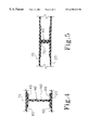
- FIG. 4 illustrates a partial cross-sectional view of the roll-over airbag taken at lines 4 — 4 in FIG. 1 .
- FIG. 5 illustrates a partial cross-sectional view of an alternate embodiment of the tether utilized in the present invention.
- FIG. 6 illustrates a perspective view of the tether illustrated in FIG. 4 .
- FIG. 7 illustrates a perspective view of the tether illustrated in FIG. 5 .
- FIG. 8 illustrates a partial schematic view of the placement locations of the roll-over airbag of the present invention.
- FIGS. 9 a-c illustrate top plan views of further alternate embodiments of the tether utilized in the present invention, in which the tethers are low profile tethers.
- FIG. 10 illustrates a cross-sectional view of the tether illustrated in FIG. 9 a , taken along line 10 — 10 in FIG. 9 a.
- FIG. 11 illustrates a partial cross-sectional view of the tether illustrated in FIG. 9 a , installed in an alternate embodiment roll-over airbag.
- FIG. 12 is a top plan view of the roll-over airbag shown in FIG. 11 .
- FIG. 13 illustrates a schematic view, not drawn to scale, of the process of RF bonding a flat lap-joint reinforced seam.
- FIG. 14 illustrates a top plan view of a preferred method of forming an internal radius lap joint.
- FIG. 15 illustrates a partial top plan view, showing the bottom panel of the roll-over airbag, of a preferred method of forming an external radius lap joint.
- FIG. 16 illustrates a partial top plan view, showing the bottom panel of the roll-over airbag, of a notched portion of the reinforcing member for forming an internal or external radius.
- FIG. 17 illustrates a top plan view of a further alternate embodiment roll-over airbag having a reinforced perimeter seal.
- FIG. 18 illustrates top plan view of a still further alternate embodiment roll-over airbag having a reinforced perimeter seal.
- a roll-over airbag constructed in accordance with the present invention, is illustrated generally as 10 in the figures.
- the roll-over airbag 10 is defined by an inflatable airbag 12 constructed of an upper fabric panel 15 having a perimeter 18 of a pre-selected length and a lower fabric panel 20 perimetrically bonded to the upper fabric panel 15 . It should be understood that reference to upper and lower panels is simply for clarity of description and is not intended to limit the spatial orientation of the roll-over airbag 10 .
- both the upper and lower fabric panels 15 and 20 are a woven nylon, or other supported fabric, in which the interior has been treated, often with a urethane coating, or coating of a similar thermoplastic that is reactive to high frequency, or radio frequency (RF), energy, in order to be impermeable to the inflation fluid.
- RF radio frequency
- other materials could be utilized so long as the result is an inflation fluid impermeable material.
- At least one port opening 25 is provided in the upper fabric panel 15 for connecting the roll-over bag 10 to an inflator (not shown) to allow communication of the expansion fluid (not shown) from the inflator to the roll-over airbag 10 .
- the perimeter edges 18 and 22 , respectively, of the upper and lower fabric panels 15 and 20 are bonded together.
- the upper and lower fabric panels 15 and 20 are secured, preferably, by a RF weld or alternatively, an ultrasonic or thermal weld.
- the coating agent is preferably reactive to RF energy in order to effect bonding.
- the upper and lower fabric panels 15 and 20 can also be secured by means of an adhesive which has a high degree of thermal stability. It will be recognized by those skilled in the art that the time for inflating and thus, expanding roll-over airbag 10 is measured in milliseconds, and that, as a result, a large amount of tear stress is placed upon the state of the art joint, or seal.
- a roll-over airbag must sustain this pressure for a longer period of time than the state of the art frontal or side impact airbag, which, by design, deflates rapidly immediately following inflation.
- a lap joint 30 is utilized using an additional piece of fabric in order to distribute the stress over a larger surface area of the upper and lower fabric panels 15 and 20 and thereby transform the tear stress into a shear stress.
- at least one securement member 32 is disposed proximate the perimeter seal such that the upper portion 34 of the securement member 32 is bonded to the upper fabric panel 15 and the lower portion 36 of the securement member 32 is bonded to the lower fabric panel 20 . Tests have shown that this reinforced perimeter seal is capable of sustaining pressure for an extended period of time.
- FIG. 16 illustrates a segment 132 that is notched so as to form either an internal radius, illustrated in FIG. 14, or an external radius, illustrated in FIG. 15 .
- an additional curved segment (not shown) can be bonded over the portion of the segment 132 that is bonded to the upper fabric panel 15 and an additional curved segment (not shown), can be bonded over the portion of the segment 132 is bonded to the lower fabric panel 20 .
- FIG. 17 illustrates a further alternate embodiment in which airbag 310 is folded along one edge 320 and which includes a centrally located region 330 that is not inflated. This effect can also be achieved by disposing at least one tether member 40 within roll-over airbag 10 for limiting displacement of the upper and lower fabric panels 15 and 20 from one another.
- the tether 40 has a first end 45 bonded to the upper fabric panel 15 , a center panel 50 , and a second end 55 bonded to the lower fabric panel 20 .
- the height of the central panel 50 is selected in order to select the height of the airbag 10 . Additional factors that determine the ultimate height of the airbag 10 are the number of tethers 40 disposed within airbag 10 and the distance between the tethers 40 . As shown in FIGS.
- the ends 45 and 55 of the tether 40 can be bonded to a substrate 60 which is in turn bonded to the upper or lower fabric panel 15 or 20 in order to reduce the risk of rupture and to strengthen the bond between the tether 40 and the upper and lower fabric panels 15 and 20 .
- the tether 40 in the preferred embodiment is at least a two ply fabric member and has a substantially I-shaped cross-section. Further, to distribute the stress of expansion over a larger surface area of the ends 45 and 55 of the tether 40 , the edges 62 and 64 of the center panel 50 have a substantially concave configuration.
- tether 40 ′ is defined by defined by a first folded fabric member 70 which is bonded to the upper fabric panel 15 and a cooperating second folded fabric member 75 .
- the folded portions of first folded fabric member 70 and second folded fabric member 75 are secured to one another by a securement member 80 , which in the preferred embodiment is defined by parallel rows of stitching.
- securement member 80 is not coextensive with the edges of the first and second folded fabric members 70 and 75 .
- first and second folded fabric members 70 and 75 have a first preselected width and securement member 80 has a second preselected width which is less than the preselected width of first and second folded fabric members 70 and 75 .
- Tether 40 ′′ is a low-profile tether.
- the tether 40 ′′ is defined by an upper panel member 140 secured to a lower panel member 145 .
- the upper and lower panels 140 and 145 are secured to one another by means of at least one region of securement 160 .
- region of securement 160 is defined by one row, and preferably at least two parallel rows, of stitching 150 .
- the terminal ends can be joined by means of an additional region of securement 165 which is wider than the region of securement 160 .
- the additional region of securement 165 is defined by a row of stitching 155 , which encloses an area having a greater width than the width of the rows of stitching 155 , and which is preferably circular or elliptical.
- region of securement 160 is defined by a substantially circular region of securement 160 ′. In this embodiment, it is preferable to include at least two circular regions of securement 160 ′ in spaced relation.
- the upper panel member 140 of the tether 40 ′′ is then bonded to the upper fabric panel 15 or 15 ′ of either roll-over airbag 10 or 10 ′, respectively, while the lower panel member 150 of the tether 40 ′′ is secured to the lower fabric panel 20 or 20 ′′ of either airbag 10 or 10 ′,respectively. While preferred methods of providing the region of securement 160 , have been described, those skilled in the art will recognize that other methods are feasible. In this regard, there are multiple stitching patterns that could be utilized to provide at least one region of securement 160 , and at least one region of securement 160 could be provided by having the upper and lower panels 140 and 145 woven together at selected areas.
- roll-over airbag 10 can be stored in the seat back at 110 , in the side pillar at 115 or proximate the headliner at 120 .
- roll-over airbag 10 it is desirable to store roll-over airbag 10 at 110 in a manner that permits a seatbelt, (not shown), to pass through the roll-over airbag 10 while folded.
- a passageway 85 is disposed in the roll-over airbag 10 .
- a first opening 87 is provided in the upper fabric panel 15 and a second opening 89 is provided in the lower panel 20 with the first opening 87 and the second opening 89 being in register.
- a channel member 90 is provided that registers with the first opening 87 and the second opening 89 .
- the channel member 90 has an upper end 92 bonded to the upper fabric panel 15 and a lower end 94 bonded to the lower fabric panel 20 , thus providing a through-opening in the roll-over airbag 10 .
- the channel member 90 is expandable.
- expansion of the channel member 90 is accomplished by providing at least one pleat 96 in the channel member 90 .
- the pleats 96 allow the channel member 90 to fold flat when the roll-over airbag 10 is deflated and allows substantially uniform expansion of the roll-over airbag 10 during inflation.
- a RF bonding machine 170 typically includes a RF generator 175 , and RF energy conducting electrodes defining a top plate 180 and a bottom plate 185 .
- the securement member 32 is positioned between the upper and lower fabric panels 15 and 20 .
- a metal form 190 is placed directly above the securement member 32 and between the upper fabric panel 15 and the top plate 180 . In this manner, a flat seam is pressed between the metal form 190 and the bottom plate 185 .
- the metal form 190 has a surface area selected to conform to the region to be bonded.
- the metal form is also in direct communication with either the top plate 180 or the bottom plate 185 and serves to provide a path of least resistance that concentrates the RF energy on the region to be bonded. It will be appreciated that the perimeter edge of the airbag can be bonded prior to positioning the securement member 32 or the securement member 32 can be positioned with respect to the upper and lower fabric panels 15 and 20 , and the perimetric edge and the lap joint bonded sequentially or simultaneously.
- metal form 190 can be a selected metal bar having a geometric surface area that conforms to the surface area of a region to be bonded and the joints are bonded sequentially, or metal form 190 could be a template (not shown) machined to bond all of the joints simultaneously.
- a template barrier 195 that is not reactive to RF energy, is disposed between the upper and lower portions of the securement member 32 .
- the template barrier 195 is repositioned as each section is bonded and is removed through an opening, such as inflator port 25 .
- the template barrier 195 can be left in the sealed airbag.
- the securement member 32 can be formed from a material that prevents the bonding agent from bleeding through the fabric, in other words, the securement member 32 can be formed of a material impervious to the bonding agent and non-reactive to radio frequency energy, in this manner the bonding agent is coated only on a side of the securement member 32 that is in contact with the first and second fabric panels, or can be coated on the non-bonded side with a thin film barrier such as Mylar. It will be appreciated by those skilled in the art that this method is useful for sealing each of the reinforced joints discussed herein. The foregoing method allows the reinforced joint to be sealed in a flat configuration in a manner that prevents wrinkling of the joint face.
- the roll-over airbag of the present invention provides a roll-over airbag that has perimetrically sealed edges that are reinforced with a sealed lap joint that renders the perimetrically sealed edges capable of sustaining pressure for an extended period of time. Further, the present invention provides a roll-over airbag that is either configured so as to limit the displacement of the sides from one another during expansion of the airbag or includes at least one internal, reinforced tether for limiting the displacement of the sides from one another during expansion of the airbag. The present invention further provides a novel method for providing a sealed flat reinforcing lap joint along the sealed edges.
Landscapes
- Engineering & Computer Science (AREA)
- Mechanical Engineering (AREA)
- Air Bags (AREA)
Priority Applications (5)
| Application Number | Priority Date | Filing Date | Title |
|---|---|---|---|
| US09/405,339 US6355123B1 (en) | 1998-07-06 | 1999-09-24 | Roll-over air bag having a reinforced perimeter seal and associated method for producing a flat reinforced seal in a roll-over air bag |
| CA002394638A CA2394638A1 (fr) | 1999-09-24 | 2000-09-14 | Dispositif de protection pneumatique en cas de tonneau dote d'une agrafe renforcee et procede de scellement |
| EP00965022A EP1409249A4 (fr) | 1999-09-24 | 2000-09-14 | Dispositif de protection pneumatique en cas de tonneau dote d'une agrafe renforcee et procede de scellement |
| PCT/US2000/025251 WO2001023183A1 (fr) | 1999-09-24 | 2000-09-14 | Dispositif de protection pneumatique en cas de tonneau dote d'une agrafe renforcee et procede de scellement |
| US10/044,996 US20020056979A1 (en) | 1998-07-06 | 2002-01-15 | Roll-over air bag having a reinforced perimeter seal and associated method for producing a flat reinforced seal in a roll-over air bag |
Applications Claiming Priority (2)
| Application Number | Priority Date | Filing Date | Title |
|---|---|---|---|
| US09/110,632 US6113141A (en) | 1998-07-06 | 1998-07-06 | Roll-over air bag |
| US09/405,339 US6355123B1 (en) | 1998-07-06 | 1999-09-24 | Roll-over air bag having a reinforced perimeter seal and associated method for producing a flat reinforced seal in a roll-over air bag |
Related Parent Applications (1)
| Application Number | Title | Priority Date | Filing Date |
|---|---|---|---|
| US09/110,632 Continuation-In-Part US6113141A (en) | 1998-07-06 | 1998-07-06 | Roll-over air bag |
Related Child Applications (1)
| Application Number | Title | Priority Date | Filing Date |
|---|---|---|---|
| US10/044,996 Division US20020056979A1 (en) | 1998-07-06 | 2002-01-15 | Roll-over air bag having a reinforced perimeter seal and associated method for producing a flat reinforced seal in a roll-over air bag |
Publications (1)
| Publication Number | Publication Date |
|---|---|
| US6355123B1 true US6355123B1 (en) | 2002-03-12 |
Family
ID=23603288
Family Applications (2)
| Application Number | Title | Priority Date | Filing Date |
|---|---|---|---|
| US09/405,339 Expired - Fee Related US6355123B1 (en) | 1998-07-06 | 1999-09-24 | Roll-over air bag having a reinforced perimeter seal and associated method for producing a flat reinforced seal in a roll-over air bag |
| US10/044,996 Abandoned US20020056979A1 (en) | 1998-07-06 | 2002-01-15 | Roll-over air bag having a reinforced perimeter seal and associated method for producing a flat reinforced seal in a roll-over air bag |
Family Applications After (1)
| Application Number | Title | Priority Date | Filing Date |
|---|---|---|---|
| US10/044,996 Abandoned US20020056979A1 (en) | 1998-07-06 | 2002-01-15 | Roll-over air bag having a reinforced perimeter seal and associated method for producing a flat reinforced seal in a roll-over air bag |
Country Status (4)
| Country | Link |
|---|---|
| US (2) | US6355123B1 (fr) |
| EP (1) | EP1409249A4 (fr) |
| CA (1) | CA2394638A1 (fr) |
| WO (1) | WO2001023183A1 (fr) |
Cited By (24)
| Publication number | Priority date | Publication date | Assignee | Title |
|---|---|---|---|---|
| US20020038950A1 (en) * | 1998-11-18 | 2002-04-04 | Yasushi Masuda | Method of forming airbag with gas preventing joining portion |
| US6489006B1 (en) * | 1999-11-17 | 2002-12-03 | Milliken & Company | Inflatable fabrics comprising peel seams which become shear seams upon inflation |
| US20040256842A1 (en) * | 1994-05-23 | 2004-12-23 | Breed David S. | Knee bolster airbag system |
| US20050127650A1 (en) * | 2003-12-10 | 2005-06-16 | Rose Larry D. | Inflatable cushion with shielded seams |
| US20050127651A1 (en) * | 2003-12-10 | 2005-06-16 | Blackburn Jeffery S. | Airbag seam pattern for increased occupant protection |
| US20050134022A1 (en) * | 2003-12-19 | 2005-06-23 | Takata Corporation | Curtain airbag device |
| US20050161917A1 (en) * | 2003-12-11 | 2005-07-28 | Stevens Bruce A. | Side curtain air bag design |
| US20060043712A1 (en) * | 2004-08-24 | 2006-03-02 | Sam Hakki | Collision air bag and flotation system |
| US20060163853A1 (en) * | 2005-01-21 | 2006-07-27 | Ramesh Keshavaraj | Air bag with gas blocking sealant at sewn seams |
| US20060192372A1 (en) * | 2005-02-28 | 2006-08-31 | Takata Restraint Systems, Inc. | Coated sewing thread for airbag and method of sealing an airbag |
| US20060292949A1 (en) * | 2005-06-24 | 2006-12-28 | Guillo Jean R | Sealing and reinforcing strips principally for airbag assembly joints |
| US20100078919A1 (en) * | 2008-09-30 | 2010-04-01 | Toyoda Gosei Co., Ltd. | Airbag |
| US20100244415A1 (en) * | 2009-03-31 | 2010-09-30 | Tk Holdings Inc. | Airbag |
| US20110074141A1 (en) * | 2009-09-29 | 2011-03-31 | Tk Holdings Inc. | Airbag module |
| US8376401B2 (en) | 2010-01-27 | 2013-02-19 | Tk Holdings Inc. | Airbag |
| US8662533B2 (en) * | 2012-05-03 | 2014-03-04 | Tk Holdings Inc. | Airbag module with light weight airbag cushion |
| US8764055B2 (en) * | 2011-09-02 | 2014-07-01 | Trw Vehicle Safety Systems Inc. | Air bag with pleated portion |
| US9067557B1 (en) * | 2014-07-14 | 2015-06-30 | Ford Global Technologies, Llc | Active bolster with heat-staked reinforcement |
| EP3127584A1 (fr) | 2015-08-05 | 2017-02-08 | Ortovox Sportartikel GmbH | Coussin gonflable pour un systeme de coussin gonflable en cas d'avalanche, systeme de coussin gonflable en cas d'avalanche et procede de fabrication d'un coussin gonflable |
| US10189209B2 (en) * | 2013-03-13 | 2019-01-29 | Dsm Ip Assets B.V. | Systems and method for producing three-dimensional articles from flexible composite materials |
| US11072143B2 (en) | 2013-03-13 | 2021-07-27 | Dsm Ip Assets B.V | Flexible composite systems and methods |
| US11090898B2 (en) | 2013-03-13 | 2021-08-17 | Dsm Ip Assets B.V. | Engineered composite systems |
| US20240092301A1 (en) * | 2022-09-16 | 2024-03-21 | Ford Global Technologies, Llc | Vehicle airbag system |
| US11945395B1 (en) | 2022-12-14 | 2024-04-02 | Ford Global Technologies, Llc | Vehicle airbag system |
Families Citing this family (9)
| Publication number | Priority date | Publication date | Assignee | Title |
|---|---|---|---|---|
| JP4743807B2 (ja) | 2000-12-20 | 2011-08-10 | タカタ株式会社 | カーテンエアバッグ |
| US20060237957A1 (en) * | 2005-04-22 | 2006-10-26 | Takata Restraint Systems, Inc. | Sealed cushion |
| US7451554B2 (en) * | 2005-10-19 | 2008-11-18 | Nike, Inc. | Fluid system having an expandable pump chamber |
| EP2020344B1 (fr) * | 2007-08-03 | 2014-07-16 | Autoliv Development AB | Poche d'air pour véhicules automobiles |
| EP2373190B1 (fr) | 2008-12-09 | 2012-05-30 | Dainese S.p.A. | Dispositif de protection comprenant un élément gonflable |
| EP2373188B1 (fr) | 2008-12-09 | 2012-02-08 | Dainese S.p.A. | Vêtement conçu pour être associé à un dispositif destiné à la protection personnelle d'un utilisateur |
| JP5996673B2 (ja) * | 2012-12-25 | 2016-09-21 | オートリブ ディベロップメント エービー | 車両用エアバッグ構造及び車両用サイドエアバッグ装置 |
| US11001222B2 (en) * | 2016-04-05 | 2021-05-11 | Felters Of South Carolina, Llc | Vehicle safety devices, seam tapes for use in airbag and related methods |
| US12384322B2 (en) * | 2022-08-03 | 2025-08-12 | Atieva, Inc. | Airbag with sacrificial elastomer line |
Citations (36)
| Publication number | Priority date | Publication date | Assignee | Title |
|---|---|---|---|---|
| US3425712A (en) | 1967-08-23 | 1969-02-04 | Eaton Yale & Towne | Safety device |
| US3807754A (en) | 1972-01-03 | 1974-04-30 | Uniroyal Inc | Passive restraint systems for vehicle occupants |
| US3879056A (en) | 1972-02-21 | 1975-04-22 | Toyoda Boshoku Kk | Safety gas bag structure |
| US3897961A (en) | 1973-05-02 | 1975-08-05 | Chrysler Corp | Inflatable restraint apparatus |
| US3960386A (en) | 1973-02-12 | 1976-06-01 | Ab Inventing | Means for expandable objects, preferably shock-absorbing protective means for passengers in vehicles |
| US3970328A (en) | 1973-02-12 | 1976-07-20 | Ab Inventing | Method and blank for manufacturing shock-absorbing safety devices for vehicle passengers |
| US4010005A (en) | 1973-06-23 | 1977-03-01 | Mitsui-Anaconda Electro Copper Sheet Co., Ltd. | Copper foil having bond strength |
| DE2552815A1 (de) | 1975-11-25 | 1977-05-26 | Phoenix Gummiwerke Ag | Aufblasbarer prallschutzbalg fuer den fahrgastraum von kraftfahrzeugen |
| JPH0231965A (ja) | 1988-07-20 | 1990-02-01 | Asahi Chem Ind Co Ltd | エアバッグ装置 |
| JPH02237837A (ja) | 1989-08-29 | 1990-09-20 | Takata Kk | エアバッグ |
| US4963412A (en) | 1988-06-17 | 1990-10-16 | Takata Corporation | Sheet material for vehicle safety air bags |
| GB2243119A (en) | 1990-03-10 | 1991-10-23 | Woodville Polymer Eng | A vehicle air bag with inflation control straps |
| CA2059639A1 (fr) | 1990-05-30 | 1991-12-01 | Akira Kokaguchi | Sac gonflable dans une unite de sac gonflable |
| US5114180A (en) | 1988-08-03 | 1992-05-19 | Asahi Kasei Kogyo Kabushiki Kaisha | Air bag |
| EP0485599A1 (fr) | 1990-05-30 | 1992-05-20 | Takata Kabushiki Kaisha | Coussin pneumatique gonflable pour installation de securite anticollision |
| GB2252983A (en) | 1990-12-27 | 1992-08-26 | Bridgestone Corp | Air bag |
| JPH04266544A (ja) | 1990-12-06 | 1992-09-22 | Basf Ag | 自動車用の膨張可能エアバッグ |
| JPH04356249A (ja) | 1991-05-31 | 1992-12-09 | Achilles Corp | 車輌用エアバック |
| JPH0516751A (ja) | 1991-07-12 | 1993-01-26 | Toyota Motor Corp | サイドエアバツグ装置の袋体構造 |
| US5427410A (en) | 1993-06-07 | 1995-06-27 | Takata Corporation | Air bag with large size and small volume |
| US5452914A (en) | 1993-04-02 | 1995-09-26 | Takata Corporation | Air bag for a motor vehicle |
| US5501259A (en) | 1994-05-02 | 1996-03-26 | Palm; Edward B. | Inflatable restraint device and method of manufacturing same |
| US5505485A (en) | 1994-05-23 | 1996-04-09 | Automotive Technologies International, Inc. | Plastic film airbag |
| US5524926A (en) | 1994-04-26 | 1996-06-11 | Takata Corporation | Air bag for protecting an occupant |
| US5529332A (en) | 1995-04-26 | 1996-06-25 | Trw Vehicle Safety Systems Inc. | Air bag module |
| US5529340A (en) | 1995-08-14 | 1996-06-25 | Morton International, Inc. | Single piece pattern air bag |
| US5540460A (en) | 1995-04-26 | 1996-07-30 | Trw Vehicle Safety Systems Inc. | Air bag module |
| US5582429A (en) | 1993-12-18 | 1996-12-10 | Dr. Ing. H.C. F. Porsche Aktiengesellschaft | Collision protection device for the occupants of a motor vehicle |
| JPH09695A (ja) | 1995-06-16 | 1997-01-07 | Sankyo Kk | 遊技機 |
| US5615914A (en) | 1995-01-17 | 1997-04-01 | Olin Corporation | Inflatable metal bladders for automobile passenger protection |
| JPH09118760A (ja) | 1995-10-24 | 1997-05-06 | Mitsubishi Rayon Co Ltd | プリプレグシート |
| US5630620A (en) | 1994-09-01 | 1997-05-20 | Takata Corporation | Reinforced thermoplastic resin film air bag |
| US5871230A (en) | 1996-06-14 | 1999-02-16 | Universal Propulsion Company, Inc. | Lap mounted inflatable bag and method of use |
| US5909895A (en) | 1996-06-11 | 1999-06-08 | Bridgestone Corporation | Thermoplastic resin film air bag |
| US6015471A (en) * | 1997-05-15 | 2000-01-18 | Manger International Limited | Inflatable cushions |
| US6059311A (en) * | 1998-02-21 | 2000-05-09 | Breed Automotive Technology, Inc. | Pillar-mounted side impact and rollover air bag |
Family Cites Families (4)
| Publication number | Priority date | Publication date | Assignee | Title |
|---|---|---|---|---|
| JP3168591B2 (ja) * | 1991-03-12 | 2001-05-21 | トヨタ自動車株式会社 | エアバッグ装置 |
| JP3665941B2 (ja) * | 1996-06-11 | 2005-06-29 | 株式会社ブリヂストン | エアバッグ |
| DE29818946U1 (de) * | 1998-10-23 | 1999-02-25 | Trw Repa Gmbh | Gassack für ein Fahrzeuginsassen-Rückhaltesystem |
| US6220629B1 (en) * | 1999-04-21 | 2001-04-24 | Breed Automotive Technology, Inc. | Cushion with increased seam strength and method of assembly |
-
1999
- 1999-09-24 US US09/405,339 patent/US6355123B1/en not_active Expired - Fee Related
-
2000
- 2000-09-14 EP EP00965022A patent/EP1409249A4/fr not_active Withdrawn
- 2000-09-14 CA CA002394638A patent/CA2394638A1/fr not_active Abandoned
- 2000-09-14 WO PCT/US2000/025251 patent/WO2001023183A1/fr not_active Ceased
-
2002
- 2002-01-15 US US10/044,996 patent/US20020056979A1/en not_active Abandoned
Patent Citations (37)
| Publication number | Priority date | Publication date | Assignee | Title |
|---|---|---|---|---|
| US3425712A (en) | 1967-08-23 | 1969-02-04 | Eaton Yale & Towne | Safety device |
| US3807754A (en) | 1972-01-03 | 1974-04-30 | Uniroyal Inc | Passive restraint systems for vehicle occupants |
| US3879056A (en) | 1972-02-21 | 1975-04-22 | Toyoda Boshoku Kk | Safety gas bag structure |
| US3960386A (en) | 1973-02-12 | 1976-06-01 | Ab Inventing | Means for expandable objects, preferably shock-absorbing protective means for passengers in vehicles |
| US3970328A (en) | 1973-02-12 | 1976-07-20 | Ab Inventing | Method and blank for manufacturing shock-absorbing safety devices for vehicle passengers |
| US3897961A (en) | 1973-05-02 | 1975-08-05 | Chrysler Corp | Inflatable restraint apparatus |
| US4010005A (en) | 1973-06-23 | 1977-03-01 | Mitsui-Anaconda Electro Copper Sheet Co., Ltd. | Copper foil having bond strength |
| DE2552815A1 (de) | 1975-11-25 | 1977-05-26 | Phoenix Gummiwerke Ag | Aufblasbarer prallschutzbalg fuer den fahrgastraum von kraftfahrzeugen |
| US4963412A (en) | 1988-06-17 | 1990-10-16 | Takata Corporation | Sheet material for vehicle safety air bags |
| JPH0231965A (ja) | 1988-07-20 | 1990-02-01 | Asahi Chem Ind Co Ltd | エアバッグ装置 |
| US5114180A (en) | 1988-08-03 | 1992-05-19 | Asahi Kasei Kogyo Kabushiki Kaisha | Air bag |
| JPH02237837A (ja) | 1989-08-29 | 1990-09-20 | Takata Kk | エアバッグ |
| GB2243119A (en) | 1990-03-10 | 1991-10-23 | Woodville Polymer Eng | A vehicle air bag with inflation control straps |
| CA2059639A1 (fr) | 1990-05-30 | 1991-12-01 | Akira Kokaguchi | Sac gonflable dans une unite de sac gonflable |
| EP0485599A1 (fr) | 1990-05-30 | 1992-05-20 | Takata Kabushiki Kaisha | Coussin pneumatique gonflable pour installation de securite anticollision |
| JPH04266544A (ja) | 1990-12-06 | 1992-09-22 | Basf Ag | 自動車用の膨張可能エアバッグ |
| GB2252983A (en) | 1990-12-27 | 1992-08-26 | Bridgestone Corp | Air bag |
| US5618595A (en) | 1990-12-27 | 1997-04-08 | Bridgestone Corporation | Air bag |
| JPH04356249A (ja) | 1991-05-31 | 1992-12-09 | Achilles Corp | 車輌用エアバック |
| JPH0516751A (ja) | 1991-07-12 | 1993-01-26 | Toyota Motor Corp | サイドエアバツグ装置の袋体構造 |
| US5452914A (en) | 1993-04-02 | 1995-09-26 | Takata Corporation | Air bag for a motor vehicle |
| US5427410A (en) | 1993-06-07 | 1995-06-27 | Takata Corporation | Air bag with large size and small volume |
| US5582429A (en) | 1993-12-18 | 1996-12-10 | Dr. Ing. H.C. F. Porsche Aktiengesellschaft | Collision protection device for the occupants of a motor vehicle |
| US5524926A (en) | 1994-04-26 | 1996-06-11 | Takata Corporation | Air bag for protecting an occupant |
| US5501259A (en) | 1994-05-02 | 1996-03-26 | Palm; Edward B. | Inflatable restraint device and method of manufacturing same |
| US5505485A (en) | 1994-05-23 | 1996-04-09 | Automotive Technologies International, Inc. | Plastic film airbag |
| US5630620A (en) | 1994-09-01 | 1997-05-20 | Takata Corporation | Reinforced thermoplastic resin film air bag |
| US5615914A (en) | 1995-01-17 | 1997-04-01 | Olin Corporation | Inflatable metal bladders for automobile passenger protection |
| US5529332A (en) | 1995-04-26 | 1996-06-25 | Trw Vehicle Safety Systems Inc. | Air bag module |
| US5540460A (en) | 1995-04-26 | 1996-07-30 | Trw Vehicle Safety Systems Inc. | Air bag module |
| JPH09695A (ja) | 1995-06-16 | 1997-01-07 | Sankyo Kk | 遊技機 |
| US5529340A (en) | 1995-08-14 | 1996-06-25 | Morton International, Inc. | Single piece pattern air bag |
| JPH09118760A (ja) | 1995-10-24 | 1997-05-06 | Mitsubishi Rayon Co Ltd | プリプレグシート |
| US5909895A (en) | 1996-06-11 | 1999-06-08 | Bridgestone Corporation | Thermoplastic resin film air bag |
| US5871230A (en) | 1996-06-14 | 1999-02-16 | Universal Propulsion Company, Inc. | Lap mounted inflatable bag and method of use |
| US6015471A (en) * | 1997-05-15 | 2000-01-18 | Manger International Limited | Inflatable cushions |
| US6059311A (en) * | 1998-02-21 | 2000-05-09 | Breed Automotive Technology, Inc. | Pillar-mounted side impact and rollover air bag |
Cited By (38)
| Publication number | Priority date | Publication date | Assignee | Title |
|---|---|---|---|---|
| US20040256842A1 (en) * | 1994-05-23 | 2004-12-23 | Breed David S. | Knee bolster airbag system |
| US6550809B1 (en) * | 1998-11-18 | 2003-04-22 | Takata Corporation | Airbag with gas preventing joining portion |
| US6712920B2 (en) * | 1998-11-18 | 2004-03-30 | Takata Corporation | Method of forming airbag with gas preventing joining portion |
| US20020038950A1 (en) * | 1998-11-18 | 2002-04-04 | Yasushi Masuda | Method of forming airbag with gas preventing joining portion |
| US6489006B1 (en) * | 1999-11-17 | 2002-12-03 | Milliken & Company | Inflatable fabrics comprising peel seams which become shear seams upon inflation |
| US7988186B2 (en) | 2003-12-10 | 2011-08-02 | Automotive Systems Laboratory, Inc. | Airbag seam pattern for increased occupant protection |
| US20050127650A1 (en) * | 2003-12-10 | 2005-06-16 | Rose Larry D. | Inflatable cushion with shielded seams |
| US20050127651A1 (en) * | 2003-12-10 | 2005-06-16 | Blackburn Jeffery S. | Airbag seam pattern for increased occupant protection |
| US7077429B2 (en) | 2003-12-10 | 2006-07-18 | Autoliv Asp, Inc. | Inflatable cushion with shielded seams |
| US20050161917A1 (en) * | 2003-12-11 | 2005-07-28 | Stevens Bruce A. | Side curtain air bag design |
| US8672351B2 (en) * | 2003-12-11 | 2014-03-18 | Automotive Systems Laboratory, Inc. | Side curtain air bag design |
| US20050134022A1 (en) * | 2003-12-19 | 2005-06-23 | Takata Corporation | Curtain airbag device |
| US20060043712A1 (en) * | 2004-08-24 | 2006-03-02 | Sam Hakki | Collision air bag and flotation system |
| US7232001B2 (en) | 2004-08-24 | 2007-06-19 | Sam Hakki | Collision air bag and flotation system |
| US20080309060A1 (en) * | 2004-08-24 | 2008-12-18 | Sam Hakki | Collision air bag and flotation system |
| US7882921B2 (en) | 2004-08-24 | 2011-02-08 | Sam Hakki | Collision air bag and flotation system |
| US20060163853A1 (en) * | 2005-01-21 | 2006-07-27 | Ramesh Keshavaraj | Air bag with gas blocking sealant at sewn seams |
| US20060192372A1 (en) * | 2005-02-28 | 2006-08-31 | Takata Restraint Systems, Inc. | Coated sewing thread for airbag and method of sealing an airbag |
| US20060292949A1 (en) * | 2005-06-24 | 2006-12-28 | Guillo Jean R | Sealing and reinforcing strips principally for airbag assembly joints |
| US7681917B2 (en) | 2005-06-24 | 2010-03-23 | Zodiac Automotive Us Inc. | Sealing and reinforcing strips principally for airbag assembly joints |
| US20100078919A1 (en) * | 2008-09-30 | 2010-04-01 | Toyoda Gosei Co., Ltd. | Airbag |
| US8348305B2 (en) * | 2008-09-30 | 2013-01-08 | Toyoda Gosei Co., Ltd. | Airbag |
| US20100244415A1 (en) * | 2009-03-31 | 2010-09-30 | Tk Holdings Inc. | Airbag |
| US8267423B2 (en) * | 2009-03-31 | 2012-09-18 | Tk Holdings Inc. | Airbag |
| US8388019B2 (en) * | 2009-09-29 | 2013-03-05 | Tk Holdings Inc. | Airbag module |
| US20110074141A1 (en) * | 2009-09-29 | 2011-03-31 | Tk Holdings Inc. | Airbag module |
| US8376401B2 (en) | 2010-01-27 | 2013-02-19 | Tk Holdings Inc. | Airbag |
| US8764055B2 (en) * | 2011-09-02 | 2014-07-01 | Trw Vehicle Safety Systems Inc. | Air bag with pleated portion |
| US8662533B2 (en) * | 2012-05-03 | 2014-03-04 | Tk Holdings Inc. | Airbag module with light weight airbag cushion |
| US10189209B2 (en) * | 2013-03-13 | 2019-01-29 | Dsm Ip Assets B.V. | Systems and method for producing three-dimensional articles from flexible composite materials |
| US11072143B2 (en) | 2013-03-13 | 2021-07-27 | Dsm Ip Assets B.V | Flexible composite systems and methods |
| EP2969502B1 (fr) * | 2013-03-13 | 2021-08-04 | DSM IP Assets B.V. | Procédé pour produire des articles en trois dimensions à partir de matériaux composites souples |
| US11090898B2 (en) | 2013-03-13 | 2021-08-17 | Dsm Ip Assets B.V. | Engineered composite systems |
| US9067557B1 (en) * | 2014-07-14 | 2015-06-30 | Ford Global Technologies, Llc | Active bolster with heat-staked reinforcement |
| EP3127584A1 (fr) | 2015-08-05 | 2017-02-08 | Ortovox Sportartikel GmbH | Coussin gonflable pour un systeme de coussin gonflable en cas d'avalanche, systeme de coussin gonflable en cas d'avalanche et procede de fabrication d'un coussin gonflable |
| US20240092301A1 (en) * | 2022-09-16 | 2024-03-21 | Ford Global Technologies, Llc | Vehicle airbag system |
| US11951925B1 (en) * | 2022-09-16 | 2024-04-09 | Ford Global Technologies, Llc | Vehicle airbag system |
| US11945395B1 (en) | 2022-12-14 | 2024-04-02 | Ford Global Technologies, Llc | Vehicle airbag system |
Also Published As
| Publication number | Publication date |
|---|---|
| EP1409249A4 (fr) | 2006-08-30 |
| CA2394638A1 (fr) | 2001-04-05 |
| EP1409249A1 (fr) | 2004-04-21 |
| US20020056979A1 (en) | 2002-05-16 |
| WO2001023183A1 (fr) | 2001-04-05 |
Similar Documents
| Publication | Publication Date | Title |
|---|---|---|
| US6355123B1 (en) | Roll-over air bag having a reinforced perimeter seal and associated method for producing a flat reinforced seal in a roll-over air bag | |
| US6113141A (en) | Roll-over air bag | |
| EP1161361B1 (fr) | Coussin gonflable | |
| JP2830963B2 (ja) | エアバッグ | |
| US6886858B2 (en) | Air bag assembly with tethers in a woven cushion and method of construction | |
| US7980585B2 (en) | Airbag mounting assemblies with double-locking wrappers | |
| JP3397041B2 (ja) | 側突用エアバッグ | |
| US6969086B2 (en) | Airbag and airbag device | |
| US20070001433A1 (en) | Head-protecting airbag and head-protecting airbag device | |
| JPH08207680A (ja) | 膨脹可能な制止クッション | |
| US6431587B1 (en) | Inflatable side curtain | |
| JP2001171471A (ja) | 膨張可能エアバッグ | |
| US20070228709A1 (en) | Airbag with gas diffuser | |
| JP2002114125A (ja) | 自動車用エアーバッグ | |
| KR100761775B1 (ko) | 에어백 | |
| US6343811B1 (en) | Inflatable rollover cushion system | |
| US7469923B2 (en) | Side airbag and method of manufacture | |
| WO2003008234A2 (fr) | Structure de cable d'attache pour airbag | |
| EP1577171B1 (fr) | Dispositif d'airbag | |
| JP3151384B2 (ja) | 膨張可能な車両乗員保護装置 | |
| WO2024102609A1 (fr) | Coussin de sécurité gonflable pour genoux | |
| EP1652737B1 (fr) | Airbag et dispositif d'airbag | |
| JP2002308035A (ja) | 頭部保護エアバッグ装置 | |
| US20070284864A1 (en) | Inflatable vehicle occupant protection device construction | |
| GB2372237A (en) | A substantially gas tight air bag |
Legal Events
| Date | Code | Title | Description |
|---|---|---|---|
| AS | Assignment |
Owner name: AMERICAN COMPONENTS, INC., TENNESSEE Free format text: ASSIGNMENT OF ASSIGNORS INTEREST;ASSIGNORS:BAKER, ROBERT A.;BAKER, ROBERT S.;REEL/FRAME:010416/0579 Effective date: 19990929 |
|
| AS | Assignment |
Owner name: METHODE MEXICO USA, INC., ILLINOIS Free format text: ASSIGNMENT OF ASSIGNORS INTEREST;ASSIGNOR:AMERICAN COMPONENTS, INC.;REEL/FRAME:012312/0038 Effective date: 20010801 |
|
| AS | Assignment |
Owner name: METHODE ELECTRONICS, INC., ILLINOIS Free format text: ASSIGNMENT OF ASSIGNORS INTEREST;ASSIGNOR:METHODE MEXICO USA, INC.;REEL/FRAME:012463/0354 Effective date: 20020106 |
|
| FEPP | Fee payment procedure |
Free format text: PAT HOLDER NO LONGER CLAIMS SMALL ENTITY STATUS, ENTITY STATUS SET TO UNDISCOUNTED (ORIGINAL EVENT CODE: STOL); ENTITY STATUS OF PATENT OWNER: LARGE ENTITY |
|
| REFU | Refund |
Free format text: REFUND - SURCHARGE, PETITION TO ACCEPT PYMT AFTER EXP, UNINTENTIONAL (ORIGINAL EVENT CODE: R2551); ENTITY STATUS OF PATENT OWNER: LARGE ENTITY |
|
| AS | Assignment |
Owner name: AMERICAN COMPONENTS, INC., TENNESSEE Free format text: PARTIAL RELEASE;ASSIGNORS:JONES, JEFFREY L.;TALLEY, P. RICHARD;REEL/FRAME:015409/0935;SIGNING DATES FROM 20010801 TO 20010811 |
|
| FPAY | Fee payment |
Year of fee payment: 4 |
|
| REMI | Maintenance fee reminder mailed | ||
| LAPS | Lapse for failure to pay maintenance fees | ||
| STCH | Information on status: patent discontinuation |
Free format text: PATENT EXPIRED DUE TO NONPAYMENT OF MAINTENANCE FEES UNDER 37 CFR 1.362 |
|
| FP | Lapsed due to failure to pay maintenance fee |
Effective date: 20100312 |