US6402196B1 - Steering wheel armature with integrated or directly mounted torque sensor for vehicle steering device - Google Patents
Steering wheel armature with integrated or directly mounted torque sensor for vehicle steering device Download PDFInfo
- Publication number
- US6402196B1 US6402196B1 US09/601,637 US60163700A US6402196B1 US 6402196 B1 US6402196 B1 US 6402196B1 US 60163700 A US60163700 A US 60163700A US 6402196 B1 US6402196 B1 US 6402196B1
- Authority
- US
- United States
- Prior art keywords
- steering wheel
- wheel frame
- frame according
- ring
- external ring
- Prior art date
- Legal status (The legal status is an assumption and is not a legal conclusion. Google has not performed a legal analysis and makes no representation as to the accuracy of the status listed.)
- Expired - Fee Related
Links
Images




Classifications
-
- B—PERFORMING OPERATIONS; TRANSPORTING
- B62—LAND VEHICLES FOR TRAVELLING OTHERWISE THAN ON RAILS
- B62D—MOTOR VEHICLES; TRAILERS
- B62D6/00—Arrangements for automatically controlling steering depending on driving conditions sensed and responded to, e.g. control circuits
- B62D6/08—Arrangements for automatically controlling steering depending on driving conditions sensed and responded to, e.g. control circuits responsive only to driver input torque
- B62D6/10—Arrangements for automatically controlling steering depending on driving conditions sensed and responded to, e.g. control circuits responsive only to driver input torque characterised by means for sensing or determining torque
-
- B—PERFORMING OPERATIONS; TRANSPORTING
- B62—LAND VEHICLES FOR TRAVELLING OTHERWISE THAN ON RAILS
- B62D—MOTOR VEHICLES; TRAILERS
- B62D1/00—Steering controls, i.e. means for initiating a change of direction of the vehicle
- B62D1/02—Steering controls, i.e. means for initiating a change of direction of the vehicle vehicle-mounted
- B62D1/04—Hand wheels
-
- G—PHYSICS
- G01—MEASURING; TESTING
- G01L—MEASURING FORCE, STRESS, TORQUE, WORK, MECHANICAL POWER, MECHANICAL EFFICIENCY, OR FLUID PRESSURE
- G01L3/00—Measuring torque, work, mechanical power, or mechanical efficiency, in general
- G01L3/02—Rotary-transmission dynamometers
- G01L3/14—Rotary-transmission dynamometers wherein the torque-transmitting element is other than a torsionally-flexible shaft
- G01L3/1407—Rotary-transmission dynamometers wherein the torque-transmitting element is other than a torsionally-flexible shaft involving springs
- G01L3/1428—Rotary-transmission dynamometers wherein the torque-transmitting element is other than a torsionally-flexible shaft involving springs using electrical transducers
-
- G—PHYSICS
- G01—MEASURING; TESTING
- G01L—MEASURING FORCE, STRESS, TORQUE, WORK, MECHANICAL POWER, MECHANICAL EFFICIENCY, OR FLUID PRESSURE
- G01L5/00—Apparatus for, or methods of, measuring force, work, mechanical power, or torque, specially adapted for specific purposes
- G01L5/22—Apparatus for, or methods of, measuring force, work, mechanical power, or torque, specially adapted for specific purposes for measuring the force applied to control members, e.g. control members of vehicles, triggers
- G01L5/221—Apparatus for, or methods of, measuring force, work, mechanical power, or torque, specially adapted for specific purposes for measuring the force applied to control members, e.g. control members of vehicles, triggers to steering wheels, e.g. for power assisted steering
Definitions
- the invention relates to the technical field of vehicle steering wheels.
- the invention concerns more particularly dynamometric steering wheels.
- Steering wheel means a manually controlled device connected to the front wheels and used by the driver to direct the vehicle.
- the steering wheel is connected to the front wheels by a steering column, that is to say a tubular element fixed to the bodywork, under the dashboard, which guides and supports the transmission shaft connected to the steering wheel.
- a steering column that is to say a tubular element fixed to the bodywork, under the dashboard, which guides and supports the transmission shaft connected to the steering wheel.
- This steering column is associated with a steering box, for example a rack, converting the circular movement of the steering wheel into an angular movement of the steering rods which cause the wheels to steer.
- a steering box for example a rack
- the invention also concerns the steering wheels integrated into the steering device in which the wheels are not connected by a series of mechanical components with the steering wheel.
- Steering wheels conventionally consist of a toric rim connected by at least one connecting arm to a hub cooperating with the steering shaft.
- EP-726 185 EP-691 254, EP-504 963, EP-412 605, EP-465 296, EP-390 001, EP-368 386, EP-329 542, EP-309 316, FR-2 679 859, FR-2 674 207, FR-2 662 132, FR-2 664 223, FR-2 620 996.
- Steering wheels frequently serve as a support for comfort or safety equipment, without any functional link with the steering column.
- Inflatable airbag means here a passive retaining device formed by a flexible casing inflated in the event of impact by an explosive system, so as to fill a space in front of the driver.
- Steering wheels with an integral airbag conventionally comprise a body formed by a rim and arms connecting to a hollow hub in which a central airbag support hub is housed.
- the invention relates to an instrumented steering wheel structure, the sensor 25 integrated into or attached to the structure or frame of the steering wheel being a torque sensor or torque meter.
- the invention relates, according to a first aspect, to a steering wheel frame, notably for a motor vehicle, having
- the means of measuring the stresses applied to the steering shaft by the manoeuvring of the steering wheel comprise at least one torque sensor.
- the steering shaft is a component of a steering column mechanically connecting the wheels to the steering wheel.
- the steering shaft is a principal shaft of a decoupled steering device.
- the means of measuring the stresses applied to the steering shaft by the manoeuvring of the steering wheel is a small-movement sensor.
- the frame comprises an annular rim and at least one arm connecting the rim to the stress measuring means.
- the frame comprises at least one ergonomic grip for gripping the steering wheel.
- the grip is fixed by clamping members to the periphery of the steering wheel or to one of the arms of the steering wheel.
- the grip supports means of controlling components of the vehicle.
- the rim comprises at least two substantially complementary tubes shaped in a portion of a ring, each tube comprising a portion of the rim and at least one-radially folded end part forming at least part of an arm of the frame.
- the radial arms are connected to the rim, the end part of one or of each arm being inserted in a corresponding slot in the rim, in one embodiment.
- the radial arm or arms are made from pressed sheet metal, the end part of one or each arm being coiled on the rim and welded thereto.
- the frame includes means of connecting an inflatable airbag device.
- the frame has means of connection either with an insert encased in padding, an inflatable airbag mechanism being encased in the padding, or with a plate connecting the steering wheel gripping means to the steering shaft.
- the torque sensor has:
- the movable external ring being able to be rigidly fixed to the steering wheel frame, the movable external ring being connected to the internal ring by at least one elastically deformable means;
- the external ring substantially unstressed, being connected to the internal ring by at least one substantially unstressed means;
- the senor comprising means of measuring small relative movements of the movable external ring with respect to the substantially unstressed external ring when a torque is applied to the steering shaft via the steering wheel frame.
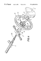
- FIG. 1 is a schematic view in exploded perspective of a vehicle steering device comprising a steering wheel with an attached torque sensor, according to one embodiment of the invention
- FIG. 2 is an exploded schematic side view corresponding to FIG. 1;
- FIG. 3 is a perspective view of a hub with a flexion sensing element according to one embodiment
- FIG. 4 is a view corresponding to FIG. 1, the hub with a flexion sensing element being integrated into the steering wheel rather than attached to it;
- FIG. 5 is an exploded schematic side view, corresponding to FIG. 4;
- FIG. 6 is a front view of the steering wheel and hub assembly as depicted in FIG. 4;
- FIG. 7 is a view in transverse section along the line VII—VII in FIG. 6;
- FIG. 8 is an exploded view in schematic perspective of a steering device having a hub with a torsion sensing element
- FIG. 9 is a view in perspective of the device depicted in FIG. 8, in the assembled position, the sensors being removed from their housing;
- FIG. 10 is a perspective view of a steering device, corresponding to FIGS. 1, 4 and 8 , the inflatable airbag box being disposed in the central part of the steering wheel;
- FIG. 11 is a rear view in the direction of the arrow A of the device depicted in FIG. 1, after assembly;
- FIGS. 12 and 13 are views in transverse section of a steering device according to one embodiment; FIG. 13 being a detail view of FIG. 12 .
- FIG. 1 Reference is made first of all to FIG. 1 .
- the steering device 1 depicted schematically in exploded perspective in FIG. 1, is intended to be integrated into a vehicle, for example a motor car.
- This device 1 comprises a steering column 2 .
- This column 2 can be telescopic, where appropriate, and/or have an inclination which is variable with respect to the bodywork or driver.
- a control assembly 3 under the steering wheel is associated with the steering device.
- the control assembly 3 under the steering wheel comprises a central block 3 a having a through hole 3 b with a diameter such that the assembly 3 can be fitted on the end part 2 a of the transmission shaft of the column 2 .
- the end part 2 a of the transmission shaft has a substantially circular transverse section, the through hole 3 b also being circular in transverse section i.e. perpendicular to the principal axis D of the steering device 1 .
- the steering device 1 comprises a rotating connector 4 provided with two bars 4 b , 4 c and a through central hole 4 a.
- the bar 4 b is intended to be held in position in a groove 3 c provided on the central block 3 a of the control assembly 3 under the steering wheel.
- the steering device 1 comprises a torque meter whose sensing element is integrated into the hub 7 of the steering wheel 5 .
- the steering wheel 5 has in its central part an inflatable airbag box 6 .
- the rotating connector 4 can serve for the connection of the inflatable airbag box 6 and for the connection between the electronic circuit 8 of the power steering torque meter and the power assistance means (electric motor, hydraulic circuit control device etc).
- the rotating electrical connector can be of the type having a first fixed casing element, a second casing element, concentric with the first fixed casing element, and able to move in rotation with respect to it, and a flexible electrically conductive member wound in a spiral between the fixed element and the movable element of the casing.
- the steering device 1 may not have an inflatable airbag box.
- the steering wheel 5 has a rim 13 and a frame 12 .
- the frame 12 is in the form of a transverse arch 12 a connected to the rim 13 by four inclined arms 12 c.
- the transverse arch 12 a has through holes 12 b allowing the passage of screws 11 for fixing the hub 7 to the steering wheel 5 .
- the hub is made in one piece with the frame of the steering wheel 5 rather than being attached to the latter.
- the rim 13 of the steering wheel 5 can, in certain embodiments, be formed from at least two substantially complementary tubes in the form of portions of rings, each tube having a curved portion forming a portion of the rim, at each end of which there is provided a radially folded portion, one end of which supports means of connection with the hub.
- the frame of the steering wheel 5 can be produced from aluminium alloy, magnesium-based alloy, semi-crystalline thermoplastic, metallic-matrix composite material, or any other equivalent material.
- the frame of the steering wheel is produced from pressed sheet metal.
- the metallic or other skeleton of the steering wheel 5 can be covered with an expanded casing made of plastics material, for example moulded onto the skeleton.
- the steering wheel can have parts covered with one or more natural products, in particular a cladding of leather or precious wood.
- the hub 7 will now be described with reference to FIG. 3 et seq.
- the hub 7 has a flexion sensing element.
- the hub 7 has a cylindrical internal ring 15 and two external rings 14 a , 14 b connected to the internal ring 14 by elastic beams 18 a deformable under flexion and non-deformed beams 19 .
- the rear external ring 14 a fixed to the hub 7 of the steering wheel 5 by screws 11 passing through the holes 21 , is connected to the internal ring 15 by means of elastic beams 18 a deformable under flexion.
- the external rings 14 a , 14 b are substantially coaxial and have the same mean diameter.
- the deformable beams 18 a are four in number, evenly distributed perpendicularly to the principal axis D.
- the deformable beams are two, three or more than four in number.
- the front external ring 14 b is connected to the internal ring 15 by means of non-deformed radial beams 19 , a web or any other substantially rigid means of connection.
- non-deformed beams 19 there are the same number of non-deformed beams 19 as there are beams elastically deformable under flexion 18 , the beams 18 a , 19 being situated substantially on two radial planes perpendicular to the principal axis D.
- the beams 19 are two, three or more than four in number, the number of beams 18 a being four.
- the thickness or height of at least one elastically deformable beam 18 a varies from its foot 30 to its head 31 .
- the movable external ring 14 a of the hub 7 is rigidly connected with the arch 12 a of the steering wheel 5 , the screws 11 passing through the holes 12 b in the arch in order to reach the holes 21 provided in the attachment lugs 25 on the external ring 14 a.
- a screw 10 fixes the steering wheel 5 to the column 2 , the control assembly 3 under the steering wheel, the rotating connector 4 , the hub 7 , being sandwiched between the arch 12 a of the steering wheel 5 and the steering column 2 , over a length corresponding to the end part 2 a of the transmission shaft of this column 2 .
- the electronic circuit 8 can be attached by adhesive bonding or any other equivalent means, on the front face of the hub 7 .
- the front external ring 14 b for its part, remains substantially unstressed, its position thus being able to serve as a reference basis for measuring the movement of the external ring 14 a.
- the front external ring 14 b carries sensors 9 for small movements, from around a few microns to a few tens of microns at a minimum.
- these sensors are two in number and are disposed in axial housings 20 provided in the front ring 14 b , in line with the ring 14 a.
- These sensors 9 can be of any suitable type: optical, capacitive, electromagnetic etc sensors.
- these sensors are Hall effect sensors.
- these sensors are magnetoresistance (MR) or giant magnetoresistance (GMR) probes.
- MR magnetoresistance
- GMR giant magnetoresistance
- Each of the Hall effect sensors can have its own associated electronic circuit.
- the number of deformable beams 18 a , their angular distribution, the thickness and height of the beams, and the material used for producing them, determine, as is clear to a person skilled in the art, the following characteristics:
- the sensing element can be produced from a material chosen from amongst the group comprising steels, cast irons, aluminium alloys or magnesium alloys.
- a 35NCD16 steel, a spheroidal graphite cast iron or an aluminium in the 7000 series can for example be envisaged.
- the sensing element can be cast or machined, depending on the material used, the geometry of the beams and the acceptable cost in particular, as can be determined by a person skilled in the art.
- FIG. 8 illustrates an embodiment of a hub with a torsion sensing element.
- the hub 7 has an unstressed external ring 14 b with a substantially cylindrical external peripheral surface.
- This ring 14 b is provided with two housings 20 provided in two diametrically opposed protrusions 33 .
- the internal surface of the ring 14 b is substantially cylindrical.
- the ring 14 b is connected to the internal ring 15 by at least one beam 19 , a web or any substantially rigid connecting element.
- two radial beams 19 or one web made in one piece with the internal ring 15 and the unstressed external ring 14 b , connect these two rings 15 , 14 a.
- the beams 19 have a substantially constant square cross-section from their foot to their head and are substantially aligned, in the embodiment depicted.
- the internal ring 15 has a through hole defining a fluted joining piece 16 and, opposite, a bearing surface 22 for the fluted joining piece on the transmission shaft of the steering column 2 , when the sensing element is intended to be incorporated in a steering column.
- a tube 18 b deformed under torsion connects the internal ring 15 to the movable external ring 14 a.
- This movable external ring 14 a is connected rigidly to the means of applying torque to the column 2 , namely the steering wheel 5 .
- Screws 11 provide, via the holes 21 , the fixing of the hub 7 to the transverse central plate 40 of the frame 12 of the steering wheel 5 .
- This plate 40 is provided with holes 12 b corresponding to the hole 21 in the hub 7 .
- the frame 12 of the steering wheel has, just like in the embodiments presented in FIGS. 1 and 4, several inclined arms 12 c connecting the transverse central plate 40 to the rim 13 of the steering wheel 5 .
- the movable external ring 14 a When the hub 7 is mounted on a steering wheel 5 , as depicted in FIG. 8, the movable external ring 14 a , fixed to the plate 40 and therefore to the rim 13 of the steering wheel 5 , is moved in rotation with respect to the unstressed external ring 14 b.
- Measurement of this small movement for example by means of Hall sensors 9 placed in the recesses 20 and magnets 9 ′ fixed opposite the plate 40 , makes it possible to measure the torque applied by the driver and affords control of the steering power assistance after processing of the signal by the electronic circuit 8 .
- the elastically deformable beams 18 a are, in some embodiments, in the form of coils.
- These coils have several bends separated by sectors which are straight or in the shape of an arc of a circle and concentric.
- These coils lie, in some embodiments, substantially in the same plane perpendicular to the axis of the transmission shaft.
- the beams which are deformable under flexion described above have, in some embodiments, cutouts.
- cutouts allow the use of the sensor as a torque limiter and can also or simultaneously permit the use of this sensor for several ranges of torque measurement.
- the stiffness of the torque meter increases in fact as soon as a larger number of beams exceeds the unstressed state (two separated portions) to a stressed state (the two portions of the beams are in contact). The stiffness increases in this way when the torque applied increases, limiting the degree of deformation of the movable ring 14 a.
Landscapes
- Engineering & Computer Science (AREA)
- Chemical & Material Sciences (AREA)
- Combustion & Propulsion (AREA)
- Transportation (AREA)
- Mechanical Engineering (AREA)
- Physics & Mathematics (AREA)
- General Physics & Mathematics (AREA)
- Air Bags (AREA)
- Steering Controls (AREA)
- Force Measurement Appropriate To Specific Purposes (AREA)
Applications Claiming Priority (3)
| Application Number | Priority Date | Filing Date | Title |
|---|---|---|---|
| FR9801294A FR2774348B1 (fr) | 1998-02-04 | 1998-02-04 | Armature de volant a capteur de couple integre ou rapporte pour dispositif de direction de vehicule |
| FR9801294 | 1998-02-04 | ||
| PCT/FR1999/000225 WO1999039962A1 (fr) | 1998-02-04 | 1999-02-03 | Armature de volant a capteur de couple integre ou rapporte pour dispositif de direction de vehicule |
Publications (1)
| Publication Number | Publication Date |
|---|---|
| US6402196B1 true US6402196B1 (en) | 2002-06-11 |
Family
ID=9522585
Family Applications (1)
| Application Number | Title | Priority Date | Filing Date |
|---|---|---|---|
| US09/601,637 Expired - Fee Related US6402196B1 (en) | 1998-02-04 | 1999-02-03 | Steering wheel armature with integrated or directly mounted torque sensor for vehicle steering device |
Country Status (8)
| Country | Link |
|---|---|
| US (1) | US6402196B1 (de) |
| EP (1) | EP1053160B1 (de) |
| JP (1) | JP2002502757A (de) |
| AU (1) | AU762325B2 (de) |
| BR (1) | BR9909749A (de) |
| DE (1) | DE69920175T2 (de) |
| FR (1) | FR2774348B1 (de) |
| WO (1) | WO1999039962A1 (de) |
Cited By (12)
| Publication number | Priority date | Publication date | Assignee | Title |
|---|---|---|---|---|
| US20030110881A1 (en) * | 2001-12-13 | 2003-06-19 | Trw Automotive Safety Systems Gmbh & Co. Kg | Steering device for a motor vehicle |
| US20040045374A1 (en) * | 2002-09-10 | 2004-03-11 | Siemens Vdo Automotive Corporation | Coupler for torque sensor |
| US20040159165A1 (en) * | 2001-03-23 | 2004-08-19 | Leopold Kostal Gmbh & Co. Kg | Torsion module of a torque detection device |
| US20050204857A1 (en) * | 2001-03-23 | 2005-09-22 | Leopold Kostal Gmbh & Co. Kg | Steering wheel for a motor vehicle |
| AT413152B (de) * | 2003-12-23 | 2005-11-15 | Avl List Gmbh | Drehmomenterfassungseinrichtung für ein lenksystem |
| WO2006005528A1 (de) * | 2004-07-10 | 2006-01-19 | Leopold Kostal Gmbh & Co. Kg | Torsionsmodul für eine drehmomenterfassungseinrichtung sowie verfahren zur herstellung eines speichenrades für ein torsionsmodul |
| US20070180931A1 (en) * | 2004-02-04 | 2007-08-09 | Ono Sokki Co., Ltd. | Torque meter |
| US20100176579A1 (en) * | 2006-09-04 | 2010-07-15 | Autoliv Development Ab | Steering wheel arrangement |
| CN102530059A (zh) * | 2011-12-25 | 2012-07-04 | 东方久乐汽车安全气囊有限公司 | 电动助力转向系统 |
| USD705708S1 (en) * | 2012-08-21 | 2014-05-27 | Cnh Industrial America Llc | Steering wheel |
| CN106904212A (zh) * | 2015-12-22 | 2017-06-30 | 福特全球技术公司 | 机动车辆的方向盘 |
| US11022510B2 (en) * | 2016-11-08 | 2021-06-01 | Lg Innotek Co., Ltd. | Torque index sensor and steering device comprising same |
Families Citing this family (5)
| Publication number | Priority date | Publication date | Assignee | Title |
|---|---|---|---|---|
| DE102008023759A1 (de) * | 2008-05-15 | 2009-11-26 | Takata-Petri Ag | Lenkvorrichtung für ein Kraftfahrzeug mit einem Lenkrad, einer Lenkwelle und einem Überlagerungsgetriebe |
| DE102009057809A1 (de) * | 2009-12-10 | 2011-06-16 | Leopold Kostal Gmbh & Co. Kg | Torsionsmodul |
| DE102009057810A1 (de) * | 2009-12-10 | 2011-06-16 | Leopold Kostal Gmbh & Co. Kg | Torsionsmodul |
| DE102010017850B4 (de) * | 2010-04-22 | 2017-09-14 | Leopold Kostal Gmbh & Co. Kg | Vorrichtung zur Anordnung an der Lenksäule eines Kraftfahrzeugs |
| DE102011080552A1 (de) * | 2011-08-05 | 2013-02-07 | Robert Bosch Gmbh | Lenkrad und Lenkmomentsensor für ein Kraftfahrzeug |
Citations (19)
| Publication number | Priority date | Publication date | Assignee | Title |
|---|---|---|---|---|
| US1488155A (en) * | 1922-05-03 | 1924-03-25 | Symington T H Co | Brake wheel |
| FR2478004A1 (fr) | 1980-03-17 | 1981-09-18 | Magneti Marelli Spa | Servo-volant electrique pour vehicules automobiles |
| US4532567A (en) * | 1983-02-18 | 1985-07-30 | General Motors Corporation | Electric power steering stall protection circuit |
| US4984474A (en) * | 1988-09-30 | 1991-01-15 | Copal Company Limited | Torque sensor |
| US5009110A (en) * | 1987-02-03 | 1991-04-23 | Zahnradfabrik Friedrichshafen, Ag. | Torque sensor, in particular for electric steering mechanism |
| EP0442091A1 (de) | 1990-02-15 | 1991-08-21 | Robert Bosch Gmbh | Messeinrichtung zur Bestimmung des Drehmoments eines rotierenden oder feststehenden Maschinenenteils |
| US5090731A (en) * | 1989-12-26 | 1992-02-25 | Toyoda Gosei Co., Ltd. | Steering wheel |
| US5195383A (en) * | 1989-12-08 | 1993-03-23 | Nippondenso Co., Ltd. | Steering torque detecting device |
| US5237880A (en) * | 1988-09-09 | 1993-08-24 | Robert Bosch Gmbh | Device for measuring a torque of a rotating machine part |
| US5450761A (en) * | 1994-07-01 | 1995-09-19 | Kop-Flex, Inc. | Torque meter |
| FR2718699A1 (fr) | 1994-04-13 | 1995-10-20 | Breed Automotive Tech | Ensemble de volant de direction de rééquipement ayant un ensemble de coussin gonflable. |
| EP0691254A1 (de) | 1994-07-08 | 1996-01-10 | Gestind M.B. Manifattura Di Bruzolo S.P.A | Lenkrad |
| US5501110A (en) * | 1992-06-26 | 1996-03-26 | The Torrington Company | Torsion measuring device for a rotating shaft |
| EP0726185A1 (de) | 1995-02-08 | 1996-08-14 | Ecia - Equipements Et Composants Pour L'industrie Automobile | Lenkradskelett, insbesondere für ein Kraftfahrzeug |
| WO1996025300A1 (en) | 1995-02-17 | 1996-08-22 | Dario Spinnato | A device with a rotating, anatomic handle for steering wheels of vehicles with electronic accelerator system |
| WO1997008527A1 (fr) | 1995-08-31 | 1997-03-06 | Snr Roulements | Dispositif de mesure de couple de torsion d'un arbre tournant |
| EP0775624A2 (de) | 1995-11-24 | 1997-05-28 | Koyo Seiko Co., Ltd. | Lenksystem für ein Kraftfahrzeug |
| US5704633A (en) * | 1995-12-19 | 1998-01-06 | United Technologies Automotive Systems, Inc. | Modular clock spring arrangement |
| US6190264B1 (en) * | 1999-04-21 | 2001-02-20 | Bi Technologies Corporation | Low-hysteresis coupling for angular-position and torque sensor |
Family Cites Families (21)
| Publication number | Priority date | Publication date | Assignee | Title |
|---|---|---|---|---|
| FR2620996B1 (fr) | 1987-09-25 | 1990-01-26 | Peugeot Aciers Et Outillage | Volant allege de direction notamment pour vehicule automobile obtenu a partir de matieres synthetiques renforcees estampables et procede pour sa fabrication |
| FR2627448B1 (fr) | 1988-02-19 | 1992-10-23 | Ecia Equip Composants Ind Auto | Volant de direction notamment pour vehicule automobile |
| FR2633237B1 (fr) | 1988-06-22 | 1992-05-15 | Centaure | Accessoire pour l'equipement du volant d'un vehicule automobile |
| IT214163Z2 (it) | 1988-06-24 | 1990-04-02 | Same Spa | Postazione di guida per trattori |
| IT215383Z2 (it) | 1988-11-09 | 1990-09-11 | Momo Spa | Volante per autoveicoli con placchette di raccordo tra razze e corona. |
| US4961331A (en) | 1989-03-29 | 1990-10-09 | Winner James E | Vehicle security system with improved steering wheel |
| DE3926576A1 (de) | 1989-08-11 | 1991-02-14 | Kolbenschmidt Ag | Lenkradskelett |
| FR2662132A1 (fr) | 1990-05-17 | 1991-11-22 | Ecia Equip Composants Ind Auto | Armature de volant de direction pour vehicule automobile ou analogue. |
| FR2664223B1 (fr) | 1990-07-03 | 1992-10-23 | Ecia Equip Composants Ind Auto | Armature de volant de direction pour vehicule automobile ou analogue. |
| DE4108973A1 (de) | 1991-03-20 | 1992-09-24 | Kolbenschmidt Ag | Lenkrad |
| FR2674207A1 (fr) | 1991-03-20 | 1992-09-25 | Ecia Equip Composants Ind Auto | Volant de direction, notamment de vehicule automobile. |
| FR2679859B1 (fr) | 1991-07-29 | 1997-04-04 | Ecia Equip Composants Ind Auto | Armature de volant de direction. |
| FR2681570A1 (fr) | 1991-09-20 | 1993-03-26 | Peugeot | Volant de direction pour vehicule automobile avec tablette porte-documents integree. |
| US5597177A (en) | 1992-11-13 | 1997-01-28 | Kabushiki Kaisha Tokai-Rika-Denki-Seisakusho | Steering wheel pad structure |
| DE4329120A1 (de) | 1993-08-30 | 1995-03-02 | Petri Ag | Lenkrad für Kraftfahrzeuge |
| IT230454Y1 (it) | 1993-10-06 | 1999-06-07 | Linea Guida Srl | Dispositivo di comando dell'accelleratore per autovetture destinate ad utenti privi dell'uso degli arti inferiori |
| FR2716857B1 (fr) | 1994-03-03 | 1997-07-18 | Autoliv Dev | Volant avec dispositif de protection anti-choc à sac gonflable prémonté. |
| CA2182776C (en) | 1994-12-07 | 1999-08-03 | Fuminori Komiya | Horn switch of steering wheel and its pad mounting structure |
| US5573606A (en) | 1995-02-16 | 1996-11-12 | Gibbs Die Casting Aluminum Corporation | Aluminum alloy and method for making die cast products |
| DE69628065T2 (de) | 1995-02-27 | 2004-04-01 | Toyoda Gosei Co., Ltd. | Verfahren zur Herstellung eines Lenkrads und durch dieses Verfahren hergestelltes Lenkrad |
| EP0788935A3 (de) | 1995-09-06 | 1998-07-29 | Toyoda Gosei Co., Ltd. | Montagestruktur für ein Lenkrad |
-
1998
- 1998-02-04 FR FR9801294A patent/FR2774348B1/fr not_active Expired - Fee Related
-
1999
- 1999-02-03 JP JP2000530413A patent/JP2002502757A/ja active Pending
- 1999-02-03 EP EP99901698A patent/EP1053160B1/de not_active Expired - Lifetime
- 1999-02-03 WO PCT/FR1999/000225 patent/WO1999039962A1/fr not_active Ceased
- 1999-02-03 AU AU21708/99A patent/AU762325B2/en not_active Ceased
- 1999-02-03 DE DE69920175T patent/DE69920175T2/de not_active Expired - Fee Related
- 1999-02-03 BR BR9909749-4A patent/BR9909749A/pt not_active IP Right Cessation
- 1999-02-03 US US09/601,637 patent/US6402196B1/en not_active Expired - Fee Related
Patent Citations (20)
| Publication number | Priority date | Publication date | Assignee | Title |
|---|---|---|---|---|
| US1488155A (en) * | 1922-05-03 | 1924-03-25 | Symington T H Co | Brake wheel |
| FR2478004A1 (fr) | 1980-03-17 | 1981-09-18 | Magneti Marelli Spa | Servo-volant electrique pour vehicules automobiles |
| US4532567A (en) * | 1983-02-18 | 1985-07-30 | General Motors Corporation | Electric power steering stall protection circuit |
| US5009110A (en) * | 1987-02-03 | 1991-04-23 | Zahnradfabrik Friedrichshafen, Ag. | Torque sensor, in particular for electric steering mechanism |
| US5237880A (en) * | 1988-09-09 | 1993-08-24 | Robert Bosch Gmbh | Device for measuring a torque of a rotating machine part |
| US4984474A (en) * | 1988-09-30 | 1991-01-15 | Copal Company Limited | Torque sensor |
| US5195383A (en) * | 1989-12-08 | 1993-03-23 | Nippondenso Co., Ltd. | Steering torque detecting device |
| US5090731A (en) * | 1989-12-26 | 1992-02-25 | Toyoda Gosei Co., Ltd. | Steering wheel |
| EP0442091A1 (de) | 1990-02-15 | 1991-08-21 | Robert Bosch Gmbh | Messeinrichtung zur Bestimmung des Drehmoments eines rotierenden oder feststehenden Maschinenenteils |
| US5501110A (en) * | 1992-06-26 | 1996-03-26 | The Torrington Company | Torsion measuring device for a rotating shaft |
| FR2718699A1 (fr) | 1994-04-13 | 1995-10-20 | Breed Automotive Tech | Ensemble de volant de direction de rééquipement ayant un ensemble de coussin gonflable. |
| US5450761A (en) * | 1994-07-01 | 1995-09-19 | Kop-Flex, Inc. | Torque meter |
| EP0691254A1 (de) | 1994-07-08 | 1996-01-10 | Gestind M.B. Manifattura Di Bruzolo S.P.A | Lenkrad |
| EP0726185A1 (de) | 1995-02-08 | 1996-08-14 | Ecia - Equipements Et Composants Pour L'industrie Automobile | Lenkradskelett, insbesondere für ein Kraftfahrzeug |
| WO1996025300A1 (en) | 1995-02-17 | 1996-08-22 | Dario Spinnato | A device with a rotating, anatomic handle for steering wheels of vehicles with electronic accelerator system |
| WO1997008527A1 (fr) | 1995-08-31 | 1997-03-06 | Snr Roulements | Dispositif de mesure de couple de torsion d'un arbre tournant |
| US5731529A (en) * | 1995-08-31 | 1998-03-24 | The Torrington Company | Device for measuring the torque of a rotating shaft |
| EP0775624A2 (de) | 1995-11-24 | 1997-05-28 | Koyo Seiko Co., Ltd. | Lenksystem für ein Kraftfahrzeug |
| US5704633A (en) * | 1995-12-19 | 1998-01-06 | United Technologies Automotive Systems, Inc. | Modular clock spring arrangement |
| US6190264B1 (en) * | 1999-04-21 | 2001-02-20 | Bi Technologies Corporation | Low-hysteresis coupling for angular-position and torque sensor |
Cited By (21)
| Publication number | Priority date | Publication date | Assignee | Title |
|---|---|---|---|---|
| US20040159165A1 (en) * | 2001-03-23 | 2004-08-19 | Leopold Kostal Gmbh & Co. Kg | Torsion module of a torque detection device |
| US6799481B2 (en) | 2001-03-23 | 2004-10-05 | Leopold Kostal Gmbh & Co. Kg | Torsion module of a torque detection device |
| US20050204857A1 (en) * | 2001-03-23 | 2005-09-22 | Leopold Kostal Gmbh & Co. Kg | Steering wheel for a motor vehicle |
| US7950690B2 (en) * | 2001-03-23 | 2011-05-31 | Leopold Kostal Gmbh & Co. Kg | Steering wheel for a motor vehicle |
| US20030110881A1 (en) * | 2001-12-13 | 2003-06-19 | Trw Automotive Safety Systems Gmbh & Co. Kg | Steering device for a motor vehicle |
| US7044021B2 (en) * | 2001-12-13 | 2006-05-16 | Trw Automotive Safety System Gmbh | Steering device for a motor vehicle |
| US20040045374A1 (en) * | 2002-09-10 | 2004-03-11 | Siemens Vdo Automotive Corporation | Coupler for torque sensor |
| US6948384B2 (en) * | 2002-09-10 | 2005-09-27 | Siemens Vdo Automotive Corporation | Coupler for torque sensor |
| AT413152B (de) * | 2003-12-23 | 2005-11-15 | Avl List Gmbh | Drehmomenterfassungseinrichtung für ein lenksystem |
| US7520182B2 (en) * | 2004-02-04 | 2009-04-21 | Ono Sokki Co., Ltd | Torque meter |
| US20070180931A1 (en) * | 2004-02-04 | 2007-08-09 | Ono Sokki Co., Ltd. | Torque meter |
| WO2006005528A1 (de) * | 2004-07-10 | 2006-01-19 | Leopold Kostal Gmbh & Co. Kg | Torsionsmodul für eine drehmomenterfassungseinrichtung sowie verfahren zur herstellung eines speichenrades für ein torsionsmodul |
| US20100176579A1 (en) * | 2006-09-04 | 2010-07-15 | Autoliv Development Ab | Steering wheel arrangement |
| US7997612B2 (en) * | 2006-09-04 | 2011-08-16 | Autoliv Development Ab | Steering wheel arrangement |
| CN102530059A (zh) * | 2011-12-25 | 2012-07-04 | 东方久乐汽车安全气囊有限公司 | 电动助力转向系统 |
| CN102530059B (zh) * | 2011-12-25 | 2015-01-07 | 东方久乐汽车安全气囊有限公司 | 电动助力转向系统 |
| CN102530059B8 (zh) * | 2011-12-25 | 2018-09-07 | 东方久乐汽车安全气囊有限公司 | 电动助力转向系统 |
| USD705708S1 (en) * | 2012-08-21 | 2014-05-27 | Cnh Industrial America Llc | Steering wheel |
| CN106904212A (zh) * | 2015-12-22 | 2017-06-30 | 福特全球技术公司 | 机动车辆的方向盘 |
| US11022510B2 (en) * | 2016-11-08 | 2021-06-01 | Lg Innotek Co., Ltd. | Torque index sensor and steering device comprising same |
| US11692890B2 (en) | 2016-11-08 | 2023-07-04 | Lg Innotek Co., Ltd. | Torque index sensor and steering device comprising same |
Also Published As
| Publication number | Publication date |
|---|---|
| AU762325B2 (en) | 2003-06-26 |
| AU2170899A (en) | 1999-08-23 |
| FR2774348B1 (fr) | 2000-03-03 |
| BR9909749A (pt) | 2001-03-20 |
| FR2774348A1 (fr) | 1999-08-06 |
| WO1999039962A1 (fr) | 1999-08-12 |
| EP1053160A1 (de) | 2000-11-22 |
| EP1053160B1 (de) | 2004-09-15 |
| JP2002502757A (ja) | 2002-01-29 |
| DE69920175T2 (de) | 2005-09-22 |
| DE69920175D1 (de) | 2004-10-21 |
Similar Documents
| Publication | Publication Date | Title |
|---|---|---|
| AU762325B2 (en) | Steering wheel armature with integrated or directly mounted torque sensor for vehicle steering device | |
| US6427542B1 (en) | Torque sensor and steering column provided with such a sensor | |
| US5894094A (en) | Wheel force measuring hub assembly | |
| US6517113B1 (en) | Steering column with torquemeter | |
| US6694828B1 (en) | Torque sensor for a turning shaft | |
| US11486778B2 (en) | Torque-angle sensor for monitoring a steering situation of a vehicle | |
| EP1940671B1 (de) | Servolenkung | |
| US8887581B2 (en) | Load-measuring bearing unit | |
| US5195383A (en) | Steering torque detecting device | |
| JP2002195897A (ja) | トルクを測定するための装置及び該装置を備えるモジュール | |
| JP2012047460A (ja) | トルク検出装置およびロボット装置 | |
| US6799481B2 (en) | Torsion module of a torque detection device | |
| JP2002350251A (ja) | トルク測定装置、同装置によるトルク測定方法、ならびに同装置を備えたステアリングコラムおよびモジュール | |
| US20030089166A1 (en) | Torque detection device | |
| US6481297B2 (en) | Torque sensor for automobiles | |
| EP2057449A2 (de) | Wandler für einen rotationskörper | |
| EP3822603A1 (de) | Drehmomentsensor | |
| TW301710B (de) | ||
| US6439063B1 (en) | Wheel load transducer | |
| US20080099272A1 (en) | Electric power steering system | |
| JPH04500556A (ja) | 回転する機械部分のトルクを測定するための測定装置 | |
| US4800764A (en) | Apparatus for sensing relative rotation between members | |
| JP2010139395A (ja) | トルクセンサ及び同センサを備えたステアリング | |
| WO2000075618A1 (en) | Method and device for determining during driving the friction between the road and the wheel of a vehicle | |
| JP7706979B2 (ja) | センサ |
Legal Events
| Date | Code | Title | Description |
|---|---|---|---|
| AS | Assignment |
Owner name: S.N.R. ROULEMENTS, FRANCE Free format text: ASSIGNMENT OF ASSIGNORS INTEREST;ASSIGNOR:NICOT, CHRISTOPHE;REEL/FRAME:011031/0478 Effective date: 20000727 |
|
| FPAY | Fee payment |
Year of fee payment: 4 |
|
| SULP | Surcharge for late payment | ||
| REMI | Maintenance fee reminder mailed | ||
| LAPS | Lapse for failure to pay maintenance fees | ||
| STCH | Information on status: patent discontinuation |
Free format text: PATENT EXPIRED DUE TO NONPAYMENT OF MAINTENANCE FEES UNDER 37 CFR 1.362 |
|
| FP | Lapsed due to failure to pay maintenance fee |
Effective date: 20100611 |