US642005A - Rotary engine. - Google Patents
Rotary engine. Download PDFInfo
- Publication number
- US642005A US642005A US70482899A US1899704828A US642005A US 642005 A US642005 A US 642005A US 70482899 A US70482899 A US 70482899A US 1899704828 A US1899704828 A US 1899704828A US 642005 A US642005 A US 642005A
- Authority
- US
- United States
- Prior art keywords
- piston
- valve
- cylinder
- abutment
- steam
- Prior art date
- Legal status (The legal status is an assumption and is not a legal conclusion. Google has not performed a legal analysis and makes no representation as to the accuracy of the status listed.)
- Expired - Lifetime
Links
Images

Classifications
-
- F—MECHANICAL ENGINEERING; LIGHTING; HEATING; WEAPONS; BLASTING
- F01—MACHINES OR ENGINES IN GENERAL; ENGINE PLANTS IN GENERAL; STEAM ENGINES
- F01C—ROTARY-PISTON OR OSCILLATING-PISTON MACHINES OR ENGINES
- F01C1/00—Rotary-piston machines or engines
- F01C1/30—Rotary-piston machines or engines having the characteristics covered by two or more groups F01C1/02, F01C1/08, F01C1/22, F01C1/24 or having the characteristics covered by one of these groups together with some other type of movement between co-operating members
- F01C1/40—Rotary-piston machines or engines having the characteristics covered by two or more groups F01C1/02, F01C1/08, F01C1/22, F01C1/24 or having the characteristics covered by one of these groups together with some other type of movement between co-operating members having the movement defined in group F01C1/08 or F01C1/22 and having a hinged member
- F01C1/46—Rotary-piston machines or engines having the characteristics covered by two or more groups F01C1/02, F01C1/08, F01C1/22, F01C1/24 or having the characteristics covered by one of these groups together with some other type of movement between co-operating members having the movement defined in group F01C1/08 or F01C1/22 and having a hinged member with vanes hinged to the outer member
Definitions
- GRANT B ROBINSON AND NELSON SEYLLER, OF SEVARD, OKLAHOMA TERRITORY.
- This invention relates to steam-engines of that class known as rotaryg and the object of the invention is to provide a simple and efficient apparatus of this character wherein all of the steam supplied thereto is employed to its best advantage and in which the eX- haust can be properly controlled and in which the piston can be driven in opposite directions with equal facility.
- the rotary engine herein illustrated consists of a cylinder or shell, a piston wheel or drum supported for rotation in opposite directions therein, said wheel or drum being provided with a piston, an abutment-valve, a piston-rod connected with said abutmentvalve and having a piston, a tube or jacket for incasing said last-mentioned piston, and exhaust-pipes leading from the cylinder or shell and into said tube or jacket, so that the exhauststeam can pass from the said cylinder to the tube for the purpose of utilizing the same to strike that piston which is connected with the abutment-valve for the purpose of operating the latter, a steam-chest, and a valve in the latter, and these parts may be constructed of any suitable material.
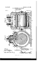
- Figure 1 is a plan view of a rotary steamengine constructed in accordance with the invention.
- Fig. 2 is a central vertical section of the same.
- Fig. 3 is a transverse central section.
- Fig. et is a sectional detail showing the abutment-valve in its extreme elevated or retracted position.
- the cylinder is denoted by A, and it has a widened base 2, adapted to rest upon and to be secured to a floor or foundation, and the heads or ends 3 and 4 of said cylinder are recessed to receive the ends of the wheel or drum B, the ends of the latter freely tting within the two recesses, as ndicated clearly in Fig. 3.
- the drum or wheel B carries the shaft 5, projecting centrally therethrough and supported for rotation in journal-openings formed, respectively, in the cylinder-heads 3 and 4. andthe hubs 2 and 3 thereon, said shaft carrying a pulley or other power transmitting device.
- the cylinder H is provided upon the upper side thereof with the steam-chest 6, co1nn1unieating with the interior of the cylinder by the vertical ports 7 and 8, which are located at opposite sides, respectively, of the abutment-valve C, hereinafter more particularly described.
- the piston-wheel B is separated from the outer wall of the cylinder A by a comparatively wide space or chamber, into which the steam from the ports 7 or 8 can pass for the purpose of striking the piston 9 to rotate the piston-wheel, said piston con sisting in the present case of a radial projection upon the periphery of the wheel, the outer face of which is in proximity to the cylinder, as clearly shown in Fig. 2.
- the abutment-valve C consists of a main plate 17, from the upper side of which the stems or rods 18 and 19 extend, said rods being vertically disposed and having at their upper ends the pistons 2O and 21, located in the tubes 22 and 23 upon the upper side of the cylinder A, said tubes having exhaust-ports, as 24, in their walls, near the top thereof, and being closed at their upper ends.
- the abutment-valve has a vertical movement up into the chamber or compartment 25 (see Fig. 4) for the purpose of crossing the path of the piston 9, as shown clearly in Fig. 4.
- the exhaust-conveying pipes 26 and 27 connect the tubes 22 and 23 with the cylinder A at opposite sides of the abutment-valve, and each of said pipes is substantially of Y shape, ⁇ the branched ends of each of them being connected with the exhaust-tubes 22 and 23, as shown clearly in Fig. 1, and each of these pipes is provided with a valve, (designated, respectively, by 28 and 29,) which valvesv are preferably of the globe type and are located adjacent to the cylinder A and are provided with Wheels, as 28' and 29, by which they can be operated.
- the abutment-valve is provided upon its lower side with the leaves or plates 30 and 3l, pivoted to opposite sides thereof, as at 30' and 31', and adapted to be thrown intoengagement alternately with the periphery of the wheel or drum B by steam-pressure, although the abutment-valve is not intended to come directly in con-tact with the drum when in its lowermost position, as indica-ted in Fig. 2.
- Fig. 2 the piston 9 is shown as being adjacent to and to the right of the abutmentvalve O, said abutment-valve being in its lowermost position and the exhaust-valve 28 being closed, while the exhaust-valve 29 is open.
- steam is admitted into the steam-chest 6 through the supply-pipe 32,lead ing thereinto, such steam will pass through the longitudinal port 7 and from thence into the cylinder A, where it willstrike the plates or leaves 30 and l0, thereby forcing the same into their shifted positions, as aforesaid, and consequently moving the piston and rotating the wheel or drum B, which carries the same, the direction of steam and of rotation of the drum being indicated by the arrows in Fig. 2.
- valve 28 will be opened and the valve 29 closed, so that the exhaust can then pass from the pipe 26 and into the tubes 22 and 23.
- the pistons 2O and 21 have reached the limit of their movement, the exhaust-steam will pass out the ports 24 in the tubes, so that the abutment-valve will be released.
- the direction of the exhaust from the pipes 26 and 27 is indicated by the arrows in Fig. 4.
- the coiled springs 33 and 34 are provided, the opposite ends of said springs being adapted to act against the plates and abutment-valve, respectively, and being fitted in depressions or concavities, as 33 and 34', formed in the abutment-valve from the opposite faces thereof.
- the steam-chest 6 contains a slide-valve 35, adapted to cover the upper ends of the ports 7 and 8 alternately, said valve being shown as uncovering the upper end of the port 7, whereby steam can enter the cylinder to the right of the abutment-valve C for the purpose of rota-ting the piston-wheel in the direction indicated.
- said valve When said valve is operated to cover the port 7, itwill uncover the port 8, so that steam can pass through the llatter to the left-hand side of the abutmentvalve for the purpose of operating said pisten-wheel in the opposite direction.
- valves' as 36 and 37, secured to the abutment-valve C and preferably fixed to the plates or leaves 30 and 3l hinged thereto.
- these supplycontrolling valves 36 and 37 which are carried therewith, are adapted to cover the lower ends of the ports 7 and 8, so as to prevent the entrance of live steam from the steam-chest into the steam-cylinder A.
- the slide-valve 35 is connected with the stem or rod 38, which extends through the steam-chest 6 and which is provided with or is connected with a suitable device (not shown) for operating said slide-valve.
- the drum or wheel B is provided near its opposite ends with the split packing-rings 39 and 40, which fit in grooves 39 and 40 therein, and which rings are adjacent to the heads or ends 3 and 4 of the cylinder, and when steam is admitted into said cylinder .in the manner hereinbefore set forth it presses against said packing rings to force them tightly against the outer walls of the grooves, thereby to prevent the escape of steam between the piston-wheel and cylinder, and said packing-rings are preferably of resilient material and are adapted to spring outwardly by their own action into proper contact with the walls of the recesses 3 and 4.
- nenT isl. ln a rotary engine, the combination with a cylinder, of a piston-Wheel therein provided with a piston, an abutment-valve movable across the path of said piston, a stem connected with the said abutment-valve, a piston on said stem, a tube inclosing said piston and having a port, and an exhaust-pipe leading from the exhaust side of the cylinder to said tube to deliver exhaust-steam to the latter and move the piston therein to move the abutment from the cylinder, substantialy as described.
- a rotary engine Ithe combination with a cylinder, of a piston-Wheel therein provided With a piston, an abutment-valve movable across the path of said piston,a stem connected to said abutment-valve and provided with a piston, a tube surrounding said last-mentioned piston and having a port, an exhaustpipe leading trom the cylinder to said tube and-adapted to deliver exhaust-steam from the cylinder to the tube to move the abutmentvalve from the cylinder, means for supplying live steam to the cylinder, and means connected with said abutment-valve for controlling the supply of steam to the cylinder, substantially as described.
- a rotary engine In a rotary engine, the combination With a cylinder, of a piston-wheel supported therein and provided with a piston, an abutmentvalve movable across the path of the piston, a stem connected with said abutment-valve, a tube surrounding said last-mentioned piston and having a port, and valved exhaustpipes leading from the cylinder at opposite sides of the abutment-valve to said tube to deliver exhaust-steam to the tube and move the abutment-valve from the cylinder, substantially as described.
- a rotary engine the combination with a cylinder, of a piston-Wheel therein provided with a piston, an abutment-valve movable across the path of said piston and having Wings hinged thereto and adapted to engage the periphery of the piston-Wheel, springs arranged between the Wings and the abutmentvalve and adapted to hold the latter normally from engagement with the surface of the piston-cylinder, a stem connected With said abutment-valve, a piston on said stem, a tube inelosing said piston and having a port, an exhaust-pipe leading from the cylinder to said tube, a supply-port leading into the cylinder, and a valve carried by said abutment-valve for covering said port thereby to cut off the supply, substantially as described.
- a rotary engine the combination with a cylinder, of a piston-Wheel therein provided With a piston, an abutment-valve movable across the path of the piston, plates connected respectively with the abutment-valve and piston, springs arranged to hold said plates normally from engagement with their respective opposing surfaces and a supply-port communicating with the cylinder, substantially as described.
- a rotary engine the combination with a cylinder, of a piston-Wheel therein provided with a piston, an abutment-valve movable across the path of said piston and separated therefrom when in its lowermost position, a
- a rotary engine the combination With a cylinder, of a piston-Wheel therein provided With a piston, an abutment-valve movable across the path of said piston, vertical stems connected with said abutment-valve and provided with pistons, tubes inclosing said pistons and having ports, valved exhaust-pipes leading from the cylinder at opposite sides of the abutment-valve to said tubes, a steamchest, ports connecting the steam-chest Wit-h the cylinder, a slide-valve in said steam-chest, spring-actuated plates connected respectively with the abutment-valve and piston upon the opposite faces thereof, and supply-controlling valves on said plates carried by the abutmentvalve and adapted to close said supply-ports, substantially as described.
Landscapes
- Engineering & Computer Science (AREA)
- Mechanical Engineering (AREA)
- General Engineering & Computer Science (AREA)
- Respiratory Apparatuses And Protective Means (AREA)
Description
No. 642,005. Patented lan. 23, |900. G. B. ROBINSON & N. SEYLLER.
BJTARY ENGINE.
(Application led Feb. 7, 1899.)
2 Sheets-Sheet I.
(No Model.)
NNN.
IIIH
Hlll H iilllllt a Ii Illllllmi .w ,Ww M m o o H l fl o i x H b. NNN H ,d W o o o im. m W, m WHW .w r1 mwd -Mmm mn JH. a. Y mw.
W m M M y 6 w 0 a ,W
W ihjz sees No. 042,005. Patented lan. 23, |900. G. B. ROBINSON & N. SEYLLER.
ROTARY ENGINE.
(Applicaton'led Feb. 7, 1899.)
2 Sheets-Sheet 2.
(No Model.)
.am .0W M. .n .h H ,o NN k.. u 1% wwmmiwmuwwl--- ----m-- QN ,.w .0N @N s co, Pnoauma. wAsHwaTuN, n. c
w: nanars UER llivrTnn STATES PATENT Ormea.
GRANT B. ROBINSON AND NELSON SEYLLER, OF SEVARD, OKLAHOMA TERRITORY.
ROTARY ENGINE.
SPECIFICATION forming part of Letters Patent No. 642,005, dated January 23, 1900.
Application filed February 7, 1899. Serial No. 7 04,828. (No model.)
Be it known that we, GRANT B. ROBINSON and NELSON SEYLLER, citizens of the United States, residing at Seward, in the county of Logan and Territory of Oklahoma, have invented a new and useful Rotary Engine, of which the following is a specication.
This invention relates to steam-engines of that class known as rotaryg and the object of the invention is to provide a simple and efficient apparatus of this character wherein all of the steam supplied thereto is employed to its best advantage and in which the eX- haust can be properly controlled and in which the piston can be driven in opposite directions with equal facility.
The rotary engine herein illustrated consists of a cylinder or shell, a piston wheel or drum supported for rotation in opposite directions therein, said wheel or drum being provided with a piston, an abutment-valve, a piston-rod connected with said abutmentvalve and having a piston, a tube or jacket for incasing said last-mentioned piston, and exhaust-pipes leading from the cylinder or shell and into said tube or jacket, so that the exhauststeam can pass from the said cylinder to the tube for the purpose of utilizing the same to strike that piston which is connected with the abutment-valve for the purpose of operating the latter, a steam-chest, and a valve in the latter, and these parts may be constructed of any suitable material.
As a means for obtaining a close union between the abutment-valve and piston-wheel and also between the piston and the outer wall of the piston chamber or cylinder these parts will be provided with hinged leaves, which are forcible into contact with the piston-wheel and piston-cylinder by the pressure of steam thereagainst and are held out of such contact by springs acting against the same.
Vith these ends in view the invention consists in the novel combination of elements and in the construction and arrangement of parts, which will be hereinafter fully described and claimed.
To enable others to understand the invention, the preferred construction thereof is illustrated in the accompanying drawings,
forming a part of this specification, and in which Figure 1 is a plan view of a rotary steamengine constructed in accordance with the invention. Fig. 2 is a central vertical section of the same. Fig. 3 is a transverse central section. Fig. et is a sectional detail showing the abutment-valve in its extreme elevated or retracted position.
Like characters denote like and corresponding parts in each of the several igures of the drawings.
In the drawings the cylinder is denoted by A, and it has a widened base 2, adapted to rest upon and to be secured to a floor or foundation, and the heads or ends 3 and 4 of said cylinder are recessed to receive the ends of the wheel or drum B, the ends of the latter freely tting within the two recesses, as ndicated clearly in Fig. 3. The drum or wheel B carries the shaft 5, projecting centrally therethrough and supported for rotation in journal-openings formed, respectively, in the cylinder- heads 3 and 4. andthe hubs 2 and 3 thereon, said shaft carrying a pulley or other power transmitting device. (Not shown.) The cylinder H is provided upon the upper side thereof with the steam-chest 6, co1nn1unieating with the interior of the cylinder by the vertical ports 7 and 8, which are located at opposite sides, respectively, of the abutment-valve C, hereinafter more particularly described. The piston-wheel B is separated from the outer wall of the cylinder A by a comparatively wide space or chamber, into which the steam from the ports 7 or 8 can pass for the purpose of striking the piston 9 to rotate the piston-wheel, said piston con sisting in the present case of a radial projection upon the periphery of the wheel, the outer face of which is in proximity to the cylinder, as clearly shown in Fig. 2. The piston 9 carries upon the opposite faces thereof the plates or leaves l0 and 12, pivoted at their inner edges, as at 10 and 12', respectively, to said piston and movable into the cut-away portions 13 and 14 therein. These plates are adapted to be thrown into engagement with the outer Wall of the steam-cylinderA by the pressure of the steam thereagainst, thereby to secure a close joint between the parts, and
IOO
for the purpose of holding the same in their outer positions the coiled springs 15 and 16 are provided, (see Fig. 2,) which act, respectively, against the plates and the piston.
The abutment-valve C consists of a main plate 17, from the upper side of which the stems or rods 18 and 19 extend, said rods being vertically disposed and having at their upper ends the pistons 2O and 21, located in the tubes 22 and 23 upon the upper side of the cylinder A, said tubes having exhaust-ports, as 24, in their walls, near the top thereof, and being closed at their upper ends. The abutment-valve has a vertical movement up into the chamber or compartment 25 (see Fig. 4) for the purpose of crossing the path of the piston 9, as shown clearly in Fig. 4. The exhaust-conveying pipes 26 and 27 connect the tubes 22 and 23 with the cylinder A at opposite sides of the abutment-valve, and each of said pipes is substantially of Y shape,` the branched ends of each of them being connected with the exhaust-tubes 22 and 23, as shown clearly in Fig. 1, and each of these pipes is provided with a valve, (designated, respectively, by 28 and 29,) which valvesv are preferably of the globe type and are located adjacent to the cylinder A and are provided with Wheels, as 28' and 29, by which they can be operated.
The abutment-valve is provided upon its lower side with the leaves or plates 30 and 3l, pivoted to opposite sides thereof, as at 30' and 31', and adapted to be thrown intoengagement alternately with the periphery of the wheel or drum B by steam-pressure, although the abutment-valve is not intended to come directly in con-tact with the drum when in its lowermost position, as indica-ted in Fig. 2.
In Fig. 2 the piston 9 is shown as being adjacent to and to the right of the abutmentvalve O, said abutment-valve being in its lowermost position and the exhaust-valve 28 being closed, while the exhaust-valve 29 is open. When steam is admitted into the steam-chest 6 through the supply-pipe 32,lead ing thereinto, such steam will pass through the longitudinal port 7 and from thence into the cylinder A, where it willstrike the plates or leaves 30 and l0, thereby forcing the same into their shifted positions, as aforesaid, and consequently moving the piston and rotating the wheel or drum B, which carries the same, the direction of steam and of rotation of the drum being indicated by the arrows in Fig. 2. When the piston in its revolution has passed a point beyond the exhaust-pipe 27, the valve 2,9 of which is open, the exhaust will pass into said pipe and from thence to the tubes 22 and 23 and will strike the pistons 2O and 2l, thereby elevating the latter,and consequently the abutment-valve A, so that the latter Will be moved across the path of the piston. To
secure the reverse operation, the valve 28 will be opened and the valve 29 closed, so that the exhaust can then pass from the pipe 26 and into the tubes 22 and 23. When the pistons 2O and 21 have reached the limit of their movement, the exhaust-steam will pass out the ports 24 in the tubes, so that the abutment-valve will be released. The direction of the exhaust from the pipes 26 and 27 is indicated by the arrows in Fig. 4.
For the purpose ot' holding the plates or leaves 30 and 31 out of contact with the outer surface of the drum or wheel B the coiled springs 33 and 34 are provided, the opposite ends of said springs being adapted to act against the plates and abutment-valve, respectively, and being fitted in depressions or concavities, as 33 and 34', formed in the abutment-valve from the opposite faces thereof.
The steam-chest 6 contains a slide-valve 35, adapted to cover the upper ends of the ports 7 and 8 alternately, said valve being shown as uncovering the upper end of the port 7, whereby steam can enter the cylinder to the right of the abutment-valve C for the purpose of rota-ting the piston-wheel in the direction indicated. When said valve is operated to cover the port 7, itwill uncover the port 8, so that steam can pass through the llatter to the left-hand side of the abutmentvalve for the purpose of operating said pisten-wheel in the opposite direction.
The supply of steam to the cylinder for the purpose of operating the piston 9 is controlled by valves', as 36 and 37, secured to the abutment-valve C and preferably fixed to the plates or leaves 30 and 3l hinged thereto. When the abutment-valve is operated in the manner hereinbefore set forth, these supplycontrolling valves 36 and 37, which are carried therewith, are adapted to cover the lower ends of the ports 7 and 8, so as to prevent the entrance of live steam from the steam-chest into the steam-cylinder A.
The slide-valve 35 is connected with the stem or rod 38, which extends through the steam-chest 6 and which is provided with or is connected with a suitable device (not shown) for operating said slide-valve.
The drum or wheel B is provided near its opposite ends with the split packing-rings 39 and 40, which fit in grooves 39 and 40 therein, and which rings are adjacent to the heads or ends 3 and 4 of the cylinder, and when steam is admitted into said cylinder .in the manner hereinbefore set forth it presses against said packing rings to force them tightly against the outer walls of the grooves, thereby to prevent the escape of steam between the piston-wheel and cylinder, and said packing-rings are preferably of resilient material and are adapted to spring outwardly by their own action into proper contact with the walls of the recesses 3 and 4.
From the preceding description it will be evident that the apparatus is simple in constr-uction, that the piston-wheel can be operated equally well in opposite directions, and that the exhaust and supply of steam can be properly and automatically controlled Without the loss of any steam.
IOO
IIO
glo
Changes in the form, proportion, size, and the minor details of construction Within the scope of the appended claims may be resorted to Wit-hout departing from the spirit or sacriiicing any of the advantages of this invention.
Having thus described the invention, what is claimed as nenT isl. ln a rotary engine, the combination with a cylinder, of a piston-Wheel therein provided with a piston, an abutment-valve movable across the path of said piston, a stem connected with the said abutment-valve, a piston on said stem, a tube inclosing said piston and having a port, and an exhaust-pipe leading from the exhaust side of the cylinder to said tube to deliver exhaust-steam to the latter and move the piston therein to move the abutment from the cylinder, substantialy as described.
2. ln a rotary engine, Ithe combination with a cylinder, of a piston-Wheel therein provided With a piston, an abutment-valve movable across the path of said piston,a stem connected to said abutment-valve and provided with a piston, a tube surrounding said last-mentioned piston and having a port, an exhaustpipe leading trom the cylinder to said tube and-adapted to deliver exhaust-steam from the cylinder to the tube to move the abutmentvalve from the cylinder, means for supplying live steam to the cylinder, and means connected with said abutment-valve for controlling the supply of steam to the cylinder, substantially as described.
3. In a rotary engine, the combination With a cylinder, of a piston-wheel supported therein and provided with a piston, an abutmentvalve movable across the path of the piston, a stem connected with said abutment-valve, a tube surrounding said last-mentioned piston and having a port, and valved exhaustpipes leading from the cylinder at opposite sides of the abutment-valve to said tube to deliver exhaust-steam to the tube and move the abutment-valve from the cylinder, substantially as described.
l. In a rotary engine, the combination with a cylinder, of a piston-Wheel therein provided with a piston, an abutment-valve movable across the path of said piston and having Wings hinged thereto and adapted to engage the periphery of the piston-Wheel, springs arranged between the Wings and the abutmentvalve and adapted to hold the latter normally from engagement with the surface of the piston-cylinder, a stem connected With said abutment-valve, a piston on said stem, a tube inelosing said piston and having a port, an exhaust-pipe leading from the cylinder to said tube, a supply-port leading into the cylinder, and a valve carried by said abutment-valve for covering said port thereby to cut off the supply, substantially as described.
5. ln a rotary engine, the combination with a cylinder, of a piston-Wheel therein provided With a piston, an abutment-valve movable across the path of the piston, plates connected respectively with the abutment-valve and piston, springs arranged to hold said plates normally from engagement with their respective opposing surfaces and a supply-port communicating with the cylinder, substantially as described.
6. In a rotary engine, the combination with a cylinder, of a piston-Wheel therein provided with a piston, an abutment-valve movable across the path of said piston, plates hinged to the abutment-valve and to the piston and movable respectively into contact with the piston-Wheel and the outer Wall of the cylinder by steam-pressure, springs arranged to hold said plates normally from engagement With their respective opposing surfaces, steamsupplying means, and an exhaust-pipe connected with the cylinder, substantially as described.
7. ln a rotary engine, the combination with a cylinder, of a piston-Wheel therein provided with a piston, an abutment-valve movable across the path of said piston and separated therefrom when in its lowermost position, a
stem connected with said abutment-valve, a
piston on said stem, a tube inclosing said piston and having a port, exhaust-pipes leading from the cylinder to said tube at opposite sides of the abutment-valve, and each of said pipes having valve plates or leaves hinged respectively to the abutment-valve and to the piston at opposite sides of each of said parts, springs acting against the plates and also against the piston and abutment-valve, ports leading into the cylinder, and supply-valves carried by the plates on said abutment-valve and serving to close said supply-ports, substantially as described.
8. In a rotary engine, the combination With a cylinder, of a piston-Wheel therein provided With a piston, an abutment-valve movable across the path of said piston, vertical stems connected with said abutment-valve and provided with pistons, tubes inclosing said pistons and having ports, valved exhaust-pipes leading from the cylinder at opposite sides of the abutment-valve to said tubes, a steamchest, ports connecting the steam-chest Wit-h the cylinder, a slide-valve in said steam-chest, spring-actuated plates connected respectively with the abutment-valve and piston upon the opposite faces thereof, and supply-controlling valves on said plates carried by the abutmentvalve and adapted to close said supply-ports, substantially as described.
In testimony that We claim the foregoing as our own we have hereto aixed our signatures in the presence of two Witnesses.
GRANT B. ROBINSON. NELSON SEYLLER.
Witnesses:
JOHN II. Sleenns, Roer. E. Cnmur.
IOO
Priority Applications (1)
| Application Number | Priority Date | Filing Date | Title |
|---|---|---|---|
| US70482899A US642005A (en) | 1899-02-07 | 1899-02-07 | Rotary engine. |
Applications Claiming Priority (1)
| Application Number | Priority Date | Filing Date | Title |
|---|---|---|---|
| US70482899A US642005A (en) | 1899-02-07 | 1899-02-07 | Rotary engine. |
Publications (1)
| Publication Number | Publication Date |
|---|---|
| US642005A true US642005A (en) | 1900-01-23 |
Family
ID=2710588
Family Applications (1)
| Application Number | Title | Priority Date | Filing Date |
|---|---|---|---|
| US70482899A Expired - Lifetime US642005A (en) | 1899-02-07 | 1899-02-07 | Rotary engine. |
Country Status (1)
| Country | Link |
|---|---|
| US (1) | US642005A (en) |
Cited By (1)
| Publication number | Priority date | Publication date | Assignee | Title |
|---|---|---|---|---|
| US2425244A (en) * | 1943-08-12 | 1947-08-05 | Jeffries Hugh | Sliding abutment unit for rotary displacement pumps or motors |
-
1899
- 1899-02-07 US US70482899A patent/US642005A/en not_active Expired - Lifetime
Cited By (1)
| Publication number | Priority date | Publication date | Assignee | Title |
|---|---|---|---|---|
| US2425244A (en) * | 1943-08-12 | 1947-08-05 | Jeffries Hugh | Sliding abutment unit for rotary displacement pumps or motors |
Similar Documents
| Publication | Publication Date | Title |
|---|---|---|
| US642005A (en) | Rotary engine. | |
| US669000A (en) | Rotary engine. | |
| US774056A (en) | Rotary engine. | |
| US633730A (en) | Rotary steam-engine. | |
| US844758A (en) | Rotary-engine. | |
| US368927A (en) | bright | |
| US390044A (en) | Rotary engine | |
| US630693A (en) | Rotary engine. | |
| US801189A (en) | Rotary engine. | |
| US807297A (en) | Rotary engine. | |
| US599751A (en) | Rotary engine | |
| US1017971A (en) | Rotary engine. | |
| US674298A (en) | Rotary engine. | |
| US833292A (en) | Rotary engine. | |
| US322353A (en) | Rotary engine | |
| US462614A (en) | Rotary engine | |
| US1047518A (en) | Rotary motor. | |
| US585333A (en) | Rotary engine | |
| US339827A (en) | Eotaey engine | |
| US646197A (en) | Motor. | |
| US753763A (en) | Rotary engine. | |
| US249620A (en) | David o | |
| US1059702A (en) | Rotary engine. | |
| US619434A (en) | phifer | |
| US777384A (en) | Rotary engine. |