US6443692B1 - Impeller for circumferential current pump and method of forming the same - Google Patents
Impeller for circumferential current pump and method of forming the same Download PDFInfo
- Publication number
- US6443692B1 US6443692B1 US09/697,935 US69793500A US6443692B1 US 6443692 B1 US6443692 B1 US 6443692B1 US 69793500 A US69793500 A US 69793500A US 6443692 B1 US6443692 B1 US 6443692B1
- Authority
- US
- United States
- Prior art keywords
- impeller
- pump
- disc
- recess portion
- circumferential current
- Prior art date
- Legal status (The legal status is an assumption and is not a legal conclusion. Google has not performed a legal analysis and makes no representation as to the accuracy of the status listed.)
- Expired - Fee Related, expires
Links
Images




Classifications
-
- F—MECHANICAL ENGINEERING; LIGHTING; HEATING; WEAPONS; BLASTING
- F04—POSITIVE - DISPLACEMENT MACHINES FOR LIQUIDS; PUMPS FOR LIQUIDS OR ELASTIC FLUIDS
- F04D—NON-POSITIVE-DISPLACEMENT PUMPS
- F04D5/00—Pumps with circumferential or transverse flow
- F04D5/002—Regenerative pumps
-
- F—MECHANICAL ENGINEERING; LIGHTING; HEATING; WEAPONS; BLASTING
- F04—POSITIVE - DISPLACEMENT MACHINES FOR LIQUIDS; PUMPS FOR LIQUIDS OR ELASTIC FLUIDS
- F04D—NON-POSITIVE-DISPLACEMENT PUMPS
- F04D29/00—Details, component parts, or accessories
- F04D29/18—Rotors
- F04D29/188—Rotors specially for regenerative pumps
Definitions
- the present invention relates to an impeller of a circumferential current pump (so-called “wesco pump”) used as an in-tank type fuel pump of an automobile and a method of forming the impeller.
- a circumferential current pump so-called “wesco pump”
- An in-tank type circumferential current pump having an improved property for being mounted to a vehicle and having a low noise and a small pressure change has been conventionally used in a fuel pump for an electronically controlled type fuel injection apparatus of an automobile.
- FIGS. 23 to 25 show a circumferential current pump 51 for an automobile.
- the circumferential current pump 51 shown in these drawings is placed within a fuel tank (not shown), and is structured such as to apply an energy to a fuel by a vane 54 formed on an outer periphery of an impeller 52 when the impeller 52 is rotated by a motor 53 so as to increase a pressure of the fuel flowing into a pump flow passage 56 from a fuel inlet port 55 and discharge the fuel having the increased pressure to an engine side from a fuel discharge port 57 .
- the sizes of the gaps w 1 and w 2 on the side surfaces 58 a and 58 b of the impeller 52 do not satisfy a desirable accuracy due to a surface accuracy of the side surfaces 58 a and 58 b of the impeller 52 , so that desired pump efficiency and discharge pressure can not be obtained.
- a width of the impeller 52 is finished at a high accuracy by polishing both of the side surfaces 58 a and 58 b of the injection molded synthetic resin impeller 52 and a surface accuracy of both of the side surfaces 58 a and 58 b of the impeller 52 is finished at a high accuracy. Therefore, the conventional impeller 52 has a disadvantage that a process and labor for working is much and a producing cost is increased (a first prior art).
- an impeller 52 structured such as to reduce a resistance applied to both of the side surfaces 58 a and 58 b in comparison with the first prior art in which a whole of both of the side surfaces 58 a and 58 b forms a seal portion, by forming an annular recess 60 in both of the side surfaces 58 a and 58 b , forming a first seal portion S 1 in an outer peripheral side thereof and forming a second seal portion S 2 in an inner peripheral side thereof (refer to Japanese Unexamined Patent Publication No. 7-151091).
- the impeller 52 is structured such that two seal portions S 1 and S 2 are formed in such a manner as to be apart from each other in a radial direction, it is necessary to polish both of the side surfaces 58 a and 58 b after the injection molding, in the same manner as that of the prior art mentioned above. Accordingly, the impeller 52 shown in FIG. 26 also has a disadvantage that a process and labor is much and a producing cost is increased in the same manner as that of the prior art mentioned above (a second prior art).
- the applicant of the present invention proposed an invention structured such that a recess portion 61 is formed in a center portion of both of the side surfaces 58 a and 58 b of the impeller 52 , a gate 62 for injection is arranged in the recess portion 61 and a pressure adjusting hole 63 is formed as shown in FIG. 27, whereby the injection molded impeller 52 can be used as it is without being polished (Japanese Unexamined Patent Publication No. 9-158885 (a third prior art)).
- Japanese Unexamined Patent Publication No. 9-158885 Japanese Unexamined Patent Publication No. 9-158885 (a third prior art)
- an object of the present invention is to provide an impeller for a circumferential current pump which can solve the disadvantages in the prior arts mentioned above, and a method of forming the same.
- an impeller for a circumferential current pump which is provided with a plurality of vane grooves in an outer peripheral side of a synthetic resin disc-like member rotated by a motor and is rotatably received within a substantially disc-like space formed between a pump casing and a pump cover, wherein a recess portion having a predetermined radius around a center of rotation is formed on at least one of one side surface opposing to the pump casing of the disc-like member and another side surface opposing to the pump cover.
- the recess portion includes a substantially disc-like recess portion around a center of rotation of the disc-like member and a substantially annular recess portion around a center of rotation of the disc-like member.
- an impeller for a circumferential current pump which is provided with a plurality of vane grooves in an outer peripheral side of a synthetic resin disc-like member rotated by a motor and is rotatably received within a substantially disc-like space formed between a pump casing and a pump cover.
- the impeller for the circumferential current pump is structured such that a recess portion having a predetermined radius around a center of rotation is formed on at least one of one side surface opposing to the pump casing of the disc-like member and another side surface opposing to the pump cover, and a plurality of grooves extending in a radial direction within the recess portion are formed in a radial shape.
- a plurality of grooves are formed in a radial shape so as to reduce a solid portion in the recess portion, whereby a cooling efficiency at a time of injection molding can be increased, a cycle time for the injection molding can be reduced, and a deformation of a whole of the impeller due to a molding shrinkage (sink mark).
- a plurality of grooves are formed in a radial shape as mentioned above and the solid portions between the grooves function as a rib, it is possible to reduce a weight without reducing a rigidity of the impeller and it is possible to reduce a used amount of the synthetic resin material.
- an impeller for a circumferential current pump as recited in any one of the first to third aspects, wherein a shape between the vane grooves on a side surface of the disc-like member is substantially rectangular.
- the impeller can be easily released from the mold after the injection molding, whereby it is possible to prevent an inferior mold release and prevent the impeller from being deformed together with the mold release.
- an impeller for a circumferential current pump as recited in any one of the first to third aspects, wherein a shape of the vane groove on a side surface of the disc-like member is formed in such a manner as to expand a groove width from an inner portion in a radial direction toward an outer portion, and a shape between the vane grooves is formed in a substantially trapezoidal shape in which a width is reduced from the inner portion in the radial direction toward the outer portion.
- the impeller can be more easily released from the mold after the injection molding than the invention described in the fourth aspect, so that it is possible to further effectively prevent the inferior mold release and prevent the impeller from being deformed together with the mold release.
- an impeller for a circumferential current pump as recited in any one of the first to fifth aspects, wherein a corner portion in a bottom portion of the vane groove is beveled.
- the impeller can be easily released from the mold after the injection molding, whereby it is possible to reduce a deformation of the impeller and an inferior mold release at a time of releasing from the mold.
- an impeller for a circumferential current pump as recited in any one of the first to sixth aspects, wherein a pressure adjusting hole extending through the another side surface from the one side surface is formed at an inner position in a radial direction from a position at which a ring gate for the injection molding is arranged, within the recess portion.
- an injected synthetic resin material is smoothly supplied to a portion of the impeller in which a surface accuracy is required.
- a pin for forming the pressure adjusting hole is arranged within a metal mold for the injection molding, whereby a surface rough portion together with a weld phenomenon is received within the recess portion even when the weld phenomenon is generated, so that the surface accuracy of the impeller side surface is not deteriorated.
- an impeller for a circumferential current pump in which a plurality of vane grooves are formed in an outer peripheral side of a synthetic resin disc-like member and a recess portion having a predetermined radius around a center of rotation is formed on at least one of one side surface of the disc-like member and another side surface thereof.
- the structure is characterized in that a ring gate for an injection molding is arranged at a position corresponding to the recess portion and a synthetic resin is injected into a cavity from the ring gate.
- a burr generated at a time of cutting the ring gate is received within the recess portion of the impeller, so that a surface accuracy of the impeller side surface is not deteriorated and it is possible to injection mold an impeller having a high accuracy.
- FIG. 1 is a front elevational view showing a part of a circumferential current pump in accordance with a first embodiment of the present invention in a broken manner;
- FIG. 2 is a view showing a part of FIG. 1 in an enlarged manner
- FIG. 3 is a cross sectional view showing a combined state between a pump casing and a pump cover
- FIGS. 4A and 4B are views for explaining an operating state of the circumferential current pump, in which FIG. 4A is a schematic plan view for explaining the operating state of the circumferential current pump and FIG. 4B is a cross sectional view along a line A—A in FIG. 4A;
- FIG. 5 is a side elevational view of an impeller
- FIG. 6 is a cross sectional view along a line B—B in FIG. 5;
- FIGS. 7A and 7B are views showing a shape of a vane groove as seen from a side surface side of the impeller, in which FIG. 7A is a view of a shape of a first vane groove and FIG. 7B is a view of a shape of a second vane groove;
- FIG. 8 is a view of a shape of the vane groove as seen from an outer peripheral surface side of the impeller
- FIG. 9 is a view showing a first modified example of the shape of the vane groove as seen from a side surface side of the impeller.
- FIG. 10 is a view showing a second modified example of the shape of the vane groove as seen from a side surface side of the impeller;
- FIG. 11 is a cross sectional view showing a relation between the impeller and a ring gate (a cross sectional view along a line C—C in FIG. 12 );
- FIG. 12 is a plan view showing a relation between the impeller and the ring gate
- FIG. 13 is a cross sectional view showing a first example of an injection molding metal mold
- FIG. 14 is a cross sectional view showing a second example of the injection molding metal mold
- FIG. 15 is a perspective view partly showing an outer appearance of an outer peripheral end portion of the impeller
- FIG. 16 is a side elevational view of the impeller showing another method of forming a pressure adjusting hole
- FIG. 17 is a side elevational view of an impeller showing a second embodiment in accordance with the present invention.
- FIG. 18 is a cross sectional view along a line D—D in FIG. 17;
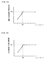
- FIG. 19 is a graph showing a relation between a dimensionless amount (L/2t) and a no-discharge pressure
- FIG. 20 is a graph showing a relation between the dimensionless amount (L/2t) and a discharge flow amount
- FIG. 21 is a partly enlarged cross sectional view of a circumferential current pump in accordance with a third embodiment of the present invention.
- FIG. 22 is a front elevational view of an impeller for the circumferential current pump in accordance with the third embodiment of the present invention.
- FIG. 23 is a front elevational view showing a part of a conventional circumferential current pump in a broken manner
- FIG. 24 is a view showing a part of FIG. 21 in an enlarged manner
- FIG. 25 is a side elevational view of an impeller showing a first conventional embodiment
- FIG. 26 is a side elevational view of an impeller showing a second conventional embodiment.
- FIG. 27 is a side elevational view of an impeller showing a third conventional embodiment.
- FIGS. 1 and 2 are views showing a circumferential current pump 1 in accordance with a first embodiment of the present invention.
- FIG. 1 is a front elevational view showing a part of the circumferential current pump 1 in a broken manner.
- FIG. 2 is a cross sectional view showing a part of FIG. 1 in an enlarged manner.
- the circumferential current pump 1 in accordance with the present embodiment is constituted by a pump portion 2 and a motor portion 3 .
- the pump portion 2 is provided with a pump casing 4 arranged in a lower end portion of the motor portion 3 , a pump cover 5 assembled in a lower surface side of the pump casing 4 , and a substantially disc-like impeller 7 rotatably received within a substantially disc-like space 6 formed between the pump casing 4 and the pump cover 5 .
- the impeller 7 is placed within a fuel tank (not shown), a phenol resin or a PPS resin excellent in a solvent resistance is used and the impeller 7 is formed in a desired shape in accordance with an injection molding.
- the impeller 7 is structured such that a plurality of vane grooves 12 are formed in each of both side surfaces 10 and 11 in an outer peripheral end portion of a disc-like member 8 and vanes 13 between the vane grooves 12 and 12 are a half pitch shifted between one side surface 10 side and another side surface 11 side, as in detail shown in FIGS. 5, 6 , 8 and 15 . Further, a disc-like recess portion 14 having a predetermined radius around a center of rotation of the impeller 7 is formed in both side surfaces 10 and 11 of the impeller 7 .
- an axial hole 15 is formed in a center portion of the impeller 7 , and a pressure adjusting hole 17 communicated with the recess portions 14 and 14 in both side surfaces 10 and 11 of the impeller 7 is formed near the axial hole 15 .
- a rotation preventing portion 16 is engaged with a notch portion (not shown) of a motor drive shaft 18 so as to receive a drive force transmitted from the motor portion 3 .
- the pressure adjusting hole 17 is structured such as to balance a pressure applied to both side surfaces 10 and 11 of the impeller 7 so as to enable the impeller 7 to rotate in a state of being a little apart from the pump casing 4 and the pump cover 5 .
- the vane groove 12 of the impeller 7 is structured such that a shape in a side surface side and a shape in an outer peripheral side are formed in a substantially rectangular shape, and an inner end portion in a radial direction is cut up so as to form a substantially circular arc shape.
- FIGS. 19 and 20 are graphs showing a relation between a radius of the recess portion 14 in the injection molded impeller 7 and a pump performance, that is, a relation between a size of a seal portion S and the pump performance (refer to FIG. 2 ).
- a horizontal axis corresponds to a dimensionless amount expressed by a rate between a size (L) of the seal portion and a gap (2t) of the impeller side surface.
- a vertical axis in FIG. 19 corresponds to a no-discharge pressure and a vertical axis in FIG. 20 corresponds to a discharge flow amount. In this case, in FIG.
- FIG. 19 shows a relation between the value (L/2t) and the non-discharge pressure.
- a fuel can be discharged to an engine side at a substantially constant non-discharge pressure (P 0 ) by setting the value so as to satisfy a relation 66 ⁇ (L/2t).
- FIG. 20 shows a relation between the value (L/2t) and the discharge flow amount.
- the fuel can be discharged at a substantially constant discharge flow amount (V 0 ) by setting the value so as to satisfy the relation 66 ⁇ (L/2t) in the same manner as the relation between the value (L/2t) and the non-discharge pressure.
- FIGS. 11 to 13 show a method of forming the impeller 7 . That is, the structure is made such that a ring gate 21 for injecting a synthetic resin within a cavity 20 for forming the impeller is arranged in a portion corresponding to the recess portion 14 of the impeller 7 .
- FIG. 13 shows an example of an injection molding metal mold 22
- the injection molding metal mold 22 is a two-separated metal mold comprising an upper die 23 and a lower die 24
- the cavity 20 for forming the impeller is formed on a joint surface between the upper die 23 and the lower die 24 .
- FIG. 14 shows another example of the injection molding metal mold 22 .
- the injection molding metal mold 22 is constituted by a first upper die 25 for forming the recess portion of the impeller 7 , a second upper die 26 arranged in an outer peripheral side of the first upper die 25 , a first low die 27 for forming the recess portion 14 of the impeller 7 and a second lower die 28 arranged in an outer peripheral side of the first lower die 27 , a separation surface 30 between the first upper die 25 and the second upper die 26 and a separation surface 31 between the first lower die 27 and the second lower die 28 are positioned in the recess portion 14 , and the ring gate 21 is formed in the first upper die 25 .
- the separation surfaces 30 and 31 of the injection molding metal mold 22 are positioned in the recess portion 14 and the ring gate 21 is positioned in the recess portion 14 , whereby a burr and a surface rough portion generated on the separation surfaces 30 and 31 of the injection molding metal mold 22 and a released surface of the ring gate 21 are received within the recess portion 14 , so that the surface accuracy of both side surfaces 10 and 11 (the seal portion S) in the impeller 7 is not deteriorated and a disadvantage that the gaps (t 1 and t 2 ) in the side of both side surfaces 10 and 11 of the impeller 7 are increased is not generated.
- FIG. 3 is a view showing a combined state between the pump casing 4 and the pump cover 5 .
- FIG. 4 is a schematic view showing a relation among a pump flow passage 32 , a fuel inlet port 33 , a fuel outlet port 34 and the impeller 7 .
- the substantially disc-like space 6 for rotatably receiving the impeller 7 is formed on the joint surface between the pump casing 4 and the pump cover 5 .
- the fuel inlet port 33 of the pump cover 5 and the fuel output port 34 of the pump casing 4 are communicated with the pump flow passage 32 formed in an outer peripheral side of the disc-like space 6 .
- a partition wall portion 36 is formed between the fuel inlet port 33 and the fuel outlet port 34 .
- a gap t 3 between a peripheral surface 36 a of the partition wall portion 36 and an outer peripheral surface 37 of the impeller 7 is set to be smaller than a gap t 4 between a peripheral surface 32 a of the pump flow passage 32 and the outer peripheral surface 37 of the impeller 7 .
- a gap between both side surfaces 36 b and 36 c of the partition wall portion 36 and both side surfaces 10 and 11 of the impeller 7 is set to a size equal to the gap size (t 1 and t 2 ) of the seal portion S in the impeller 7 .
- the gap in the side of the outer peripheral surface 37 of the impeller 7 and in the side of both side surfaces 10 and 11 is rapidly narrowed by the partition wall portion 36 , whereby the fuel having the increased pressure is prevented from being leaked out to the fuel inlet port 33 side from the fuel outlet port 34 side. Further, the fuel within the pump flow passage 32 is prevented by the seal portion S of the impeller 7 from being leaked out inward in a radial direction.
- the seal portion S is formed in a limited range in an inner peripheral side of the vane groove 12 at only one portion and a width of the seal portion S is short, the surface accuracy (a flatness, a total run-out tolerance in an axial direction, a surface roughness and the like) of the seal portion S is high even in the impeller 7 immediately after being injection molded, and a polishing of the impeller 7 is not required. Therefore, in accordance with the present embodiment, it is possible to reduce a process and labor for working the impeller 7 in comparison with the first prior art and the second prior art, so that it is possible to reduce a producing cost.
- the circumferential current pump 1 using the impeller 7 in accordance with the present embodiment can achieve a more excellent pump performance.
- the impeller 7 can be easily released from the mold after the injection molding and a deformation of the impeller 7 at a time of releasing from the mold and an inferior mold release can be reduced.
- the impeller 7 after the injection molding can be easily released from the mold and it is possible to prevent the inferior mold release and prevent the impeller 7 from being deformed together with the mold release.
- a size of the root portion of the vane 13 is largely changed when the root portion of the vane 13 is narrower than the front end portion in the outer peripheral side of the vane 13 since the vane 13 of the impeller 7 after the injection molding is structured such as to shrink toward a root portion thereof.
- the impeller 7 can be more easily released from the mold after the injection molding than the aspect shown in FIG. 9 .
- the pressure adjusting hole 17 may be positioned at any suitable positions as far as in an inner peripheral side of the ring gate 21 (in a hatched portion in FIG. 16) without being limited to the embodiment mentioned above. Further, the number of the pressure adjusting holes 17 is not limited to that of the embodiment mentioned above, and a plurality of pressure adjusting holes 17 may be formed.
- the weld phenomenon means a line-like surface rough phenomenon generated at a time when the injected synthetic resin flow is brought into contact with the pin for forming the pressure adjusting hole 17 and branched and the branched synthetic resin flow is again combined in the downstream side of the pin.
- FIGS. 17 and 18 show a second embodiment in accordance with the present invention.
- the same reference numerals are attached to the same elements as those of the first embodiment mentioned above, and a description will be given in detail with omitting an overlapping description.
- a basic structure is the same as the first embodiment mentioned above, however, the present embodiment is different from the first embodiment in a point that a plurality of radially extending grooves 40 are formed in a radial shape.
- a plurality of grooves 40 are formed in a radial shape and the solid portion in the recess portion 14 is reduced, whereby a cooling efficiency at a time of injection molding is increased and a cycle time for injection molding is reduced, so that a produced number per a unit time is increased and a production efficiency of the impeller 7 is improved.
- the radially left solid portion 41 between the grooves 40 and 40 functions as a rib by forming the groove 40 in a radial shape, it is possible to prevent a rigidity of the impeller 7 from being reduced as well as it is possible to reduce the weight of the impeller 7 , so that it is possible to reduce a deformation of the impeller 7 generated at a protruding step in the injection molding.
- FIGS. 21 and 22 show a third embodiment in accordance with the present invention.
- FIG. 21 is a partly enlarged cross sectional view of a circumferential current pump.
- FIG. 22 is a front elevational view of an impeller 7 A for the circumferential current pump.
- the impeller 7 A is structured such that a plurality of vane grooves 12 A are formed in a peripheral direction of each of both side surfaces 10 and 11 in the outer peripheral side of the disc-like member 8 .
- the vane groove 12 A is constituted by an outer peripheral end wall 9 , vanes 13 A and 13 A positioned at front and rear in a rotational direction of the disc-like member 8 and a circular arc-like wall portion 19 cut upward toward a radially inner direction of the disc-like member 8 so as to form a circular arc shape, and is structured such that the vane grooves 12 A and 12 A in the side of both side surfaces 10 and 11 are communicated with each other by an opening portion 29 .
- the impeller 7 A is structured such that the substantially disc-like recess portion 14 is formed at a position in an inner side in a radial direction from the portion where the vane groove 12 A of the disc-like member 8 is formed.
- annular pump flow passage 32 A and 32 A formed in the pump casing 4 and the pump cover 5 in such a manner as to oppose to the vane groove 12 A of the impeller 7 A.
- the pump flow passage 32 A is formed in a substantially semicircular shape in a cross section for generating a swirling current 39 as shown in FIG. 21 .
- the pump flow passage 32 A is communicated with a fuel inflow port (not shown) and a fuel outflow port (not shown).
- a gap between one side surface 10 of the impeller 7 A and the pump casing 4 is set to t 1 and a gap between another side surface 11 of the impeller 7 A and the pump cover 5 is set to t 2 .
- a radius of the disc-like member 8 is set to R 0
- a radius of the disc-like recess portion 14 is set to R 1
- a radially groove length of the vane groove 12 is set to H.
- reference symbol CL denotes a center of rotation of the impeller 7 A.
- the present embodiment in the same manner as the first embodiment mentioned above, it is possible to make the size L of the seal portion S smaller than the third prior art and it is possible to make the surface accuracy of the seal portion S higher than the third prior art.
- the present embodiment can use the injection molded impeller 7 A as it is in the same manner as the first embodiment mentioned above, and the polishing of both side surfaces 10 and 11 in the impeller 7 A which is required in the first and second prior arts is not required, so that the same effects as those of the first embodiment can be obtained.
- the radius (R 1 ) of the recess portion 14 is not limited to each of the embodiments mentioned above and may be suitably set within a range 66 ⁇ (L/2t) by taking the surface accuracy of the seal portion S into consideration.
- the recess portion 14 is formed on both side surfaces 10 and 11 of the impellers 7 and 7 A in a symmetrical manner, however, is not limited to this and may be formed on at least one side surface of both side surfaces 10 and 11 of the impellers 7 and 7 A as far as the required pump performance is satisfied. Further, the recess portion 14 may be formed in a nonsymmetrical manner as far as the radius (R 1 ) of the recess portion 14 satisfies a condition 66 ⁇ (L/2t). In addition, in each of the embodiments mentioned above, a boss portion which is not used as a seal portion may be formed in a substantially center portion of the disc-like member 8 (that is, a substantially center portion of the disc-like recess portion).
Landscapes
- Engineering & Computer Science (AREA)
- Mechanical Engineering (AREA)
- General Engineering & Computer Science (AREA)
- Structures Of Non-Positive Displacement Pumps (AREA)
Applications Claiming Priority (2)
| Application Number | Priority Date | Filing Date | Title |
|---|---|---|---|
| JP30650499A JP3907887B2 (ja) | 1999-10-28 | 1999-10-28 | 円周流ポンプ用インペラ |
| JP11-306504 | 1999-10-28 |
Publications (1)
| Publication Number | Publication Date |
|---|---|
| US6443692B1 true US6443692B1 (en) | 2002-09-03 |
Family
ID=17957831
Family Applications (1)
| Application Number | Title | Priority Date | Filing Date |
|---|---|---|---|
| US09/697,935 Expired - Fee Related US6443692B1 (en) | 1999-10-28 | 2000-10-27 | Impeller for circumferential current pump and method of forming the same |
Country Status (4)
| Country | Link |
|---|---|
| US (1) | US6443692B1 (fr) |
| EP (2) | EP1096151B1 (fr) |
| JP (1) | JP3907887B2 (fr) |
| DE (1) | DE60028689T2 (fr) |
Cited By (7)
| Publication number | Priority date | Publication date | Assignee | Title |
|---|---|---|---|---|
| US6641361B2 (en) * | 2001-12-12 | 2003-11-04 | Visteon Global Technologies, Inc. | Fuel pump impeller for high flow applications |
| US20030228212A1 (en) * | 2002-06-07 | 2003-12-11 | Hitachi Unisia Automotive, Ltd. | Turbine fuel pump |
| US20040022652A1 (en) * | 2002-08-02 | 2004-02-05 | Aisan Kogyo Kabushiki Kaisha | Low noise impeller pumps |
| US20060120852A1 (en) * | 2004-12-03 | 2006-06-08 | Mitsubishi Denki Kabushiki Kaisha | Circumferential flow pump |
| US20140255199A1 (en) * | 2013-03-07 | 2014-09-11 | Aisan Kogyo Kabushiki Kaisha | Rotator |
| US20160369818A1 (en) * | 2015-06-17 | 2016-12-22 | Denso Corporation | Fuel pump |
| US20170211576A1 (en) * | 2016-01-27 | 2017-07-27 | Higra Industrial Ltda | Progressive vortex pump |
Families Citing this family (4)
| Publication number | Priority date | Publication date | Assignee | Title |
|---|---|---|---|---|
| JP4827779B2 (ja) * | 2007-03-28 | 2011-11-30 | 株式会社ミツバ | 燃料ポンプ |
| IT1400403B1 (it) * | 2010-06-08 | 2013-05-31 | 3Mpumps Srl Ora M Pumps Srl | Pompa periferica. |
| JP6182997B2 (ja) * | 2013-06-24 | 2017-08-23 | 株式会社デンソー | 燃料ポンプ |
| JP6587536B2 (ja) * | 2015-12-24 | 2019-10-09 | 株式会社エンプラス | インペラの射出成形金型及びインペラの射出成形方法 |
Citations (7)
| Publication number | Priority date | Publication date | Assignee | Title |
|---|---|---|---|---|
| DE3313950A1 (de) | 1982-04-21 | 1983-10-27 | Aisan Kogyo K.K., Obu, Aichi | Elektrisch angetriebene pumpe |
| US4451213A (en) | 1981-03-30 | 1984-05-29 | Nippondenso Co., Ltd. | Electrically operated fuel pump device having a regenerative component |
| US4923365A (en) * | 1987-03-14 | 1990-05-08 | Robert Bosch Gmbh | Impeller wheel for conveying a medium |
| JPH07151091A (ja) | 1993-11-29 | 1995-06-13 | Aisan Ind Co Ltd | インペラ式フューエルポンプ |
| US5429476A (en) | 1992-12-22 | 1995-07-04 | Robert Bosch Gmbh | Fuel pump |
| JPH09158885A (ja) * | 1995-12-11 | 1997-06-17 | Enplas Corp | 燃料ポンプ用インペラー |
| JPH10259789A (ja) | 1997-03-19 | 1998-09-29 | Enplas Corp | ポンプ用インペラ−及びその成形方法 |
Family Cites Families (2)
| Publication number | Priority date | Publication date | Assignee | Title |
|---|---|---|---|---|
| US4854830A (en) * | 1987-05-01 | 1989-08-08 | Aisan Kogyo Kabushiki Kaisha | Motor-driven fuel pump |
| JP3228446B2 (ja) * | 1993-03-30 | 2001-11-12 | 株式会社デンソー | ウエスコポンプ |
-
1999
- 1999-10-28 JP JP30650499A patent/JP3907887B2/ja not_active Expired - Fee Related
-
2000
- 2000-10-27 EP EP00123566A patent/EP1096151B1/fr not_active Expired - Lifetime
- 2000-10-27 DE DE60028689T patent/DE60028689T2/de not_active Expired - Fee Related
- 2000-10-27 EP EP05026615A patent/EP1635067A3/fr not_active Withdrawn
- 2000-10-27 US US09/697,935 patent/US6443692B1/en not_active Expired - Fee Related
Patent Citations (7)
| Publication number | Priority date | Publication date | Assignee | Title |
|---|---|---|---|---|
| US4451213A (en) | 1981-03-30 | 1984-05-29 | Nippondenso Co., Ltd. | Electrically operated fuel pump device having a regenerative component |
| DE3313950A1 (de) | 1982-04-21 | 1983-10-27 | Aisan Kogyo K.K., Obu, Aichi | Elektrisch angetriebene pumpe |
| US4923365A (en) * | 1987-03-14 | 1990-05-08 | Robert Bosch Gmbh | Impeller wheel for conveying a medium |
| US5429476A (en) | 1992-12-22 | 1995-07-04 | Robert Bosch Gmbh | Fuel pump |
| JPH07151091A (ja) | 1993-11-29 | 1995-06-13 | Aisan Ind Co Ltd | インペラ式フューエルポンプ |
| JPH09158885A (ja) * | 1995-12-11 | 1997-06-17 | Enplas Corp | 燃料ポンプ用インペラー |
| JPH10259789A (ja) | 1997-03-19 | 1998-09-29 | Enplas Corp | ポンプ用インペラ−及びその成形方法 |
Non-Patent Citations (2)
| Title |
|---|
| Patent Abstracts of Japan, vol. 1995, No. 09, Oct. 31, 1995 & JP 07 151091A (Aisan Ind Co Ltd), Jun. 13, 1995. |
| Patent Abstracts of Japan, vol. 1998, No. 14, Dec. 31, 1998 & JP 10 259789A (Enplas Corp; Keihin Corp), Sep. 29, 1998. |
Cited By (12)
| Publication number | Priority date | Publication date | Assignee | Title |
|---|---|---|---|---|
| US6641361B2 (en) * | 2001-12-12 | 2003-11-04 | Visteon Global Technologies, Inc. | Fuel pump impeller for high flow applications |
| US20030228212A1 (en) * | 2002-06-07 | 2003-12-11 | Hitachi Unisia Automotive, Ltd. | Turbine fuel pump |
| US6796764B2 (en) * | 2002-06-07 | 2004-09-28 | Hitachi Unisia Automotive, Ltd. | Turbine fuel pump |
| US20040022652A1 (en) * | 2002-08-02 | 2004-02-05 | Aisan Kogyo Kabushiki Kaisha | Low noise impeller pumps |
| US7244094B2 (en) * | 2002-08-02 | 2007-07-17 | Aisan Kogyo Kabushiki Kaisha | Low noise impeller pumps |
| US20060120852A1 (en) * | 2004-12-03 | 2006-06-08 | Mitsubishi Denki Kabushiki Kaisha | Circumferential flow pump |
| US7290979B2 (en) * | 2004-12-03 | 2007-11-06 | Mitsubishi Denki Kabushiki Kaisha | Circumferential flow pump |
| US20140255199A1 (en) * | 2013-03-07 | 2014-09-11 | Aisan Kogyo Kabushiki Kaisha | Rotator |
| US10309411B2 (en) * | 2013-03-07 | 2019-06-04 | Arm Limited | Rotator |
| US20160369818A1 (en) * | 2015-06-17 | 2016-12-22 | Denso Corporation | Fuel pump |
| US20170211576A1 (en) * | 2016-01-27 | 2017-07-27 | Higra Industrial Ltda | Progressive vortex pump |
| US10060436B2 (en) * | 2016-01-27 | 2018-08-28 | Higra Industrial Ltda | Progressive vortex pump |
Also Published As
| Publication number | Publication date |
|---|---|
| EP1635067A3 (fr) | 2006-03-22 |
| DE60028689T2 (de) | 2007-05-24 |
| EP1635067A2 (fr) | 2006-03-15 |
| JP2001123986A (ja) | 2001-05-08 |
| EP1096151B1 (fr) | 2006-06-14 |
| DE60028689D1 (de) | 2006-07-27 |
| EP1096151A3 (fr) | 2002-03-13 |
| JP3907887B2 (ja) | 2007-04-18 |
| EP1096151A2 (fr) | 2001-05-02 |
Similar Documents
| Publication | Publication Date | Title |
|---|---|---|
| EP1766235B1 (fr) | Turbocompresseur à suralimentation hydraulic | |
| US5730582A (en) | Impeller for radial flow devices | |
| EP0646726B1 (fr) | Pompe à carburant | |
| EP1096151B1 (fr) | Rouet pour pompe à écoulement latéral | |
| JPH06229388A (ja) | 再生ポンプおよびインペラの製造方法 | |
| US4732541A (en) | Centrifugal elastomeric coated impellers | |
| JP3756337B2 (ja) | 流体ポンプ | |
| US20080085181A1 (en) | Fuel pump | |
| EP1138953B1 (fr) | Roteur d'une pompe régénérative | |
| EP0563957B1 (fr) | Pompe à carburant | |
| JP2004332739A (ja) | 燃料ポンプインペラ | |
| US6336788B1 (en) | Regenerative type pumps | |
| EP1207296A1 (fr) | Pompe de combustible résistant à l'usure | |
| US6533537B1 (en) | Impeller for circumferential current pump | |
| EP0383238A2 (fr) | Ventilateur à tourbillon et sa méthode de fabrication | |
| JP4972984B2 (ja) | 両吸込渦巻ポンプおよびその羽根車並びに羽根車の製造方法 | |
| JP2002339889A (ja) | 円周流ポンプ用インペラ | |
| JP2003181884A (ja) | 射出成形樹脂回転体及びその製造方法 | |
| JP4072886B2 (ja) | 円周流ポンプ用インペラの射出成形方法、円周流ポンプ用インペラ及び円周流ポンプ | |
| US7125218B2 (en) | Circumferential flow pump | |
| JPH04339198A (ja) | ウォータポンプ用ロータ | |
| JP4827779B2 (ja) | 燃料ポンプ | |
| JP4552221B2 (ja) | 燃料ポンプ | |
| CN113775563A (zh) | 叶轮出口结构及具有其的离心泵 | |
| JPH0988865A (ja) | 摩擦再生ポンプ |
Legal Events
| Date | Code | Title | Description |
|---|---|---|---|
| AS | Assignment |
Owner name: ENPLAS CORPORATION, JAPAN Free format text: ASSIGNMENT OF ASSIGNORS INTEREST;ASSIGNORS:SAKAMOTO, YASUYUKI;TATSUZAWA, NAOTAKA;TAKEUCHI, YOICHI;REEL/FRAME:011505/0734 Effective date: 20010115 |
|
| FPAY | Fee payment |
Year of fee payment: 4 |
|
| REMI | Maintenance fee reminder mailed | ||
| LAPS | Lapse for failure to pay maintenance fees | ||
| STCH | Information on status: patent discontinuation |
Free format text: PATENT EXPIRED DUE TO NONPAYMENT OF MAINTENANCE FEES UNDER 37 CFR 1.362 |
|
| FP | Lapsed due to failure to pay maintenance fee |
Effective date: 20100903 |