US6447264B1 - Compressor system - Google Patents
Compressor system Download PDFInfo
- Publication number
- US6447264B1 US6447264B1 US09/777,210 US77721001A US6447264B1 US 6447264 B1 US6447264 B1 US 6447264B1 US 77721001 A US77721001 A US 77721001A US 6447264 B1 US6447264 B1 US 6447264B1
- Authority
- US
- United States
- Prior art keywords
- air
- opening
- compartment
- compressor
- housing
- Prior art date
- Legal status (The legal status is an assumption and is not a legal conclusion. Google has not performed a legal analysis and makes no representation as to the accuracy of the status listed.)
- Expired - Lifetime
Links
Images




Classifications
-
- F—MECHANICAL ENGINEERING; LIGHTING; HEATING; WEAPONS; BLASTING
- F04—POSITIVE - DISPLACEMENT MACHINES FOR LIQUIDS; PUMPS FOR LIQUIDS OR ELASTIC FLUIDS
- F04B—POSITIVE-DISPLACEMENT MACHINES FOR LIQUIDS; PUMPS
- F04B39/00—Component parts, details, or accessories, of pumps or pumping systems specially adapted for elastic fluids, not otherwise provided for in, or of interest apart from, groups F04B25/00 - F04B37/00
- F04B39/06—Cooling; Heating; Prevention of freezing
- F04B39/066—Cooling by ventilation
-
- F—MECHANICAL ENGINEERING; LIGHTING; HEATING; WEAPONS; BLASTING
- F04—POSITIVE - DISPLACEMENT MACHINES FOR LIQUIDS; PUMPS FOR LIQUIDS OR ELASTIC FLUIDS
- F04B—POSITIVE-DISPLACEMENT MACHINES FOR LIQUIDS; PUMPS
- F04B39/00—Component parts, details, or accessories, of pumps or pumping systems specially adapted for elastic fluids, not otherwise provided for in, or of interest apart from, groups F04B25/00 - F04B37/00
- F04B39/0027—Pulsation and noise damping means
- F04B39/0033—Pulsation and noise damping means with encapsulations
-
- F—MECHANICAL ENGINEERING; LIGHTING; HEATING; WEAPONS; BLASTING
- F04—POSITIVE - DISPLACEMENT MACHINES FOR LIQUIDS; PUMPS FOR LIQUIDS OR ELASTIC FLUIDS
- F04B—POSITIVE-DISPLACEMENT MACHINES FOR LIQUIDS; PUMPS
- F04B39/00—Component parts, details, or accessories, of pumps or pumping systems specially adapted for elastic fluids, not otherwise provided for in, or of interest apart from, groups F04B25/00 - F04B37/00
- F04B39/0027—Pulsation and noise damping means
- F04B39/0033—Pulsation and noise damping means with encapsulations
- F04B39/0038—Pulsation and noise damping means with encapsulations of inlet or outlet channels
-
- F—MECHANICAL ENGINEERING; LIGHTING; HEATING; WEAPONS; BLASTING
- F04—POSITIVE - DISPLACEMENT MACHINES FOR LIQUIDS; PUMPS FOR LIQUIDS OR ELASTIC FLUIDS
- F04C—ROTARY-PISTON, OR OSCILLATING-PISTON, POSITIVE-DISPLACEMENT MACHINES FOR LIQUIDS; ROTARY-PISTON, OR OSCILLATING-PISTON, POSITIVE-DISPLACEMENT PUMPS
- F04C23/00—Combinations of two or more pumps, each being of rotary-piston or oscillating-piston type, specially adapted for elastic fluids; Pumping installations specially adapted for elastic fluids; Multi-stage pumps specially adapted for elastic fluids
Definitions
- Conventional air compressors typically include a compressor, a motor to drive the compressor and an air and oil cooling system to cool the compressed air and lubricating oil.
- Conventional air compressors are usually enclosed within a housing.
- a blower, fan or the like draws air into or pushes air through an opening in the housing. Some of the air which enters the housing is drawn into the compressor for ultimate use and the remaining portion of the air passes through the housing to cool the compressor, the motor, the air and oil cooling system, and other components before being discharged from the housing.
- FIG. 1 schematically illustrates a conventional compressor system 10 .
- the compressor system 10 includes a housing 14 having an air intake opening 18 and an air outlet opening 22 .
- a compressor i.e., airend
- a motor or drive train operatively connected to the compressor are housed within the housing 14 .
- a fan 26 is positioned downstream from the airend of the compressor and motor to draw air in through the air intake opening 18 . Some of the air drawn into the housing is compressed in the airend of the compressor and some of the air flows over the compressor and motor to cool the compressor and motor.
- the fan 26 also pushes the air through a plenum box 30 which is used to distribute the air over an air and oil cooler 34 before pushing the air out of the air outlet opening 22 .
- a problem with the known compressor system described above is the large amount of noise that emanates from the openings in the housing.
- the air flowing through the housing to cool the compressor and motor flows, for the most part, in a linear path from the air intake opening in the housing through the air outlet opening in the housing.
- Noise generated by the compressor and motor is freely emitted through the openings in the housing because there is no significant obstruction or other sound reducing means within the housing to reduce the amount of noise which can be carried out of the housing.
- a feature of the present invention is to provide a compressor system having a housing which includes separate compartments.
- a first compartment houses an air and oil cooling system for the compressed air and lubricating oil.
- a second compartment houses a compressor and motor which generate most of the operating noise of the compressor system.
- a large portion of air drawn in through an air intake opening of the housing is directed to cool the air and oil cooling system positioned in the first compartment.
- a smaller portion of air drawn in through the air intake opening of the housing is directed into the second compartment to cool the compressor and motor.
- the second compartment is substantially closed, except for a first limited opening to allow the required amount of cooling air in and a second limited opening to allow the cooling air to exit.
- the compressor and motor are substantially isolated from the air intake opening and air outlet opening in the housing, thereby reducing the amount of noise generated by the compressor and motor that would normally emanate out such openings. Limiting the amount of cooling air which flows over the noise generating compressor and motor also reduces the amount of air-born noise which can exit out of the openings of the housing.
- Another feature of the present invention is to provide a compressor system which regulates the amount of air fed to the compression chamber of a compressor, the amount of air used to cool an air and oil cooling system for the compressed air and lubricating oil, and the amount of air which cools the compressor and motor, all for the purpose of reducing the amount of noise emitted from an air intake opening and an air outlet opening in the housing of the compressor system.
- the present invention provides in one aspect thereof, an air directing device which receives a stream of air flowing through an air intake opening in the compressor system housing. A portion of air drawn in through the air intake opening of the housing is caused to cool the air and oil cooling system for the compressed air and lubricating oil.
- Another portion of air drawn in through the air intake opening of the housing is separated into two streams of air by the air directing device.
- the first separated stream of air is fed to a compression chamber of the compressor.
- the second separated stream of air is directed through a non-linear path to flow over the compressor and motor to cool the compressor and motor, and then out of the air outlet opening in the housing. Because only a small portion of the air entering the compressor system housing is actually used to cool the compressor and motor, and because the air used to cool the compressor and motor travels in a non-linear path through the compressor housing, the amount of noise generated by the compressor and motor that emanates from the openings in the compressor housing is greatly reduced, as compared to conventional compressor systems.
- FIG. 1 is a schematic illustration of a conventional compressor system.
- FIG. 2 is a schematic illustration of a compressor system embodying the present invention.
- FIG. 3 is a schematic illustration of an air directing device according to one aspect of the present invention.
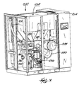
- FIG. 4 is a perspective view showing the top, back and right side panels of the compressor system housing according to the present invention.
- FIG. 5 is a perspective view showing the top, front and right side panels of the compressor system housing according to the present invention.
- FIG. 6 is a perspective view of the compressor system according to the present invention with the top, back and right side panels shown in FIG. 4 removed.
- FIG. 7 is a perspective view of the compressor system according to the present invention with the top, front and right side panels shown in FIG. 5 removed.
- FIG. 8 is a right side plan view of the compressor system of FIGS. 6-7 with the right side panel shown in FIGS. 4-5 removed.
- FIG. 9 is a front side plan view of the compressor system of FIGS. 6-7 with the front side panel shown in FIG. 5 removed.
- FIG. 2 schematically illustrates a compressor system 100 embodying the present invention.
- a feature of the present invention is to provide a compressor system having reduced noise emission during operation.
- Another feature of the present invention is to provide a compressor system which better utilizes the air drawn into the compressor system for actual use and for cooling purposes.
- the compressor system 100 includes a housing 104 having an air intake opening 108 , an air outlet opening 112 , a first compartment 116 , and a second compartment 120 .
- a blower 124 positioned within the first compartment 116 draws air through the air intake opening 108 (shown by arrow 128 ), through the first compartment 116 , and discharges the air out of the air outlet opening 112 (shown by arrows 132 ).
- a compressor 136 having an airend, and a motor or drive train 140 operatively connected to the compressor are positioned within the second compartment 120 .
- the second compartment 120 is substantially closed from the atmosphere outside the compressor system 100 , except for a restricted first air inlet opening 144 which communicates with the air intake opening 108 of the housing 104 , and a restricted second air outlet opening 148 which communicates with the blower 124 .
- the blower 124 draws air through the air inlet opening 144 , through the second compartment 120 , through the air outlet opening 148 (shown by arrow 152 ), and discharges the air out of the air outlet opening 112 of the housing 104 .
- the air flowing through the second compartment 120 cools the compressor 136 and motor 140 .
- the boundaries of the second compartment 120 and the non-linear path of the air flow into and out of the second compartment 120 provide a sound barrier for the noise generated by the compressor 136 and motor 140 located within the second compartment 120 .
- the compressor system 100 schematically illustrated in FIG. 2 could have other configurations, so long as the compressor 136 and motor 140 are isolated or spaced away from the air intake opening 108 and the air outlet opening 112 , and so long as the cooling air which flows over the compressor 136 and motor 140 does not flow in a substantially linear path from the air intake opening 108 through the air outlet opening 112 .
- the compressor 136 may be any suitable compressor, however, for the purposes of the preferred embodiment, the compressor 136 is an oil-flooded air compressor. As generally known, the oil fed into the compressor 136 must be removed from the stream of compressed air before the compressed air may be used downstream for pneumatic equipment and/or other tools.
- an air and oil cooler or heat exchanger 156 for the compressed air and lubricating oil is provided.
- the heat exchanger 156 is positioned within the first compartment 116 adjacent to the air intake opening 108 .
- the blower 124 draws air through the heat exchanger 156 to cool the compressed air and lubricating oil traveling therethrough.
- an air plenum box 160 is positioned within the first compartment 116 between the heat exchanger 156 and the blower 124 to distribute the air passing therethrough.
- the air outlet opening 148 in the second compartment 120 is an aperture in the air plenum box 160 .
- the blower 124 causes the pressure within the air plenum box 160 to be less than atmospheric pressure. A majority of the air drawn into the housing 104 by the blower 124 flows through the first compartment 116 to cool the heat exchanger 156 , into the low pressure air plenum box 160 , through the blower 124 , and then out of the air outlet opening 112 in the housing 104 .
- the air inlet opening 144 of the second compartment 120 can be an opening for an air directing device 162 .
- the air directing device 162 includes a first air flow channel (shown by arrow 164 ) for a first stream of air to be discharged from a first air exit opening 168 into an air inlet opening (not shown) of the compressor 136 , and a second air flow channel (shown by arrow 172 ) for a second stream of air to be discharged from a second air exit opening 176 into the second compartment 120 to cool the compressor 136 and motor 140 .
- a partition 180 is provided in the flow path 164 to regulate the amount of air flowing through the flow path 164 .
- the openings 144 , 168 , 176 , and 148 are sized to provide a flow of air through the second compartment 120 to prevent the compressor 136 and motor 140 from overheating, and to ensure that the right amount of air flows into the air inlet opening of the compressor 136 so that the compressor 136 does not starve because of a lack of air.
- FIGS. 4-9 illustrate a preferred compressor system 200 .
- the compressor system 200 includes a housing 204 having a top side panel 208 , a back side panel 212 , a front side panel 216 , a right side panel 220 , and a left side panel 224 .
- An air intake opening 228 is provided in the back side panel 212
- an air outlet opening 232 is provided in the top side panel 208 .
- the top 208 , back 212 , front 216 , and right 220 side panels have been removed to show the inner compartments and equipment of the compressor system 200 .
- the compressor system 200 includes a compressor 236 (FIGS. 7 and 9 ), a motor 240 (FIG. 6) operatively connected to the compressor 236 , a separator tank 244 (FIGS. 6-9) in fluid flow communication with the compressor 236 for separating the compressed air and oil from the air/oil mixture received from the compressor 236 , an air and oil cooler 248 (FIGS. 6 and 8) for cooling the compressed air received from separator tank 244 via hose 252 (FIGS. 6-9) and for cooling the oil received from the separator tank 244 via hose 256 (FIGS. 6 - 9 ), a hose 260 (FIGS.
- the compressor system 200 further includes an air intake directing device or enclosure 272 (FIG. 6 and see also 162 in FIG. 3) removably mounted within the housing 204 .
- the air intake enclosure 272 includes an air inlet opening 276 (FIG. 6 and see also 144 in FIG. 3) to receive a stream of air flowing through the air intake opening 228 (FIG. 4) of the housing 204 .
- the air intake enclosure 272 includes a first air flow channel 164 (FIG. 3) between the air inlet opening 276 and a first air exit opening 168 (FIG. 3 ), and a second air flow channel 172 between the air inlet opening 276 and a second air exit opening 176 (FIG. 3 ).
- the air intake enclosure 272 is preferably lined with sound absorbing material to reduce the amount of noise which may travel therethrough.
- a tube or hose 280 (FIGS. 7 and 9, and see also FIG. 3) is connected to the first air exit opening 168 of the air intake enclosure 272 and an air inlet opening 284 (FIG. 7) of the compressor 236 .
- an air filter 288 (FIGS. 7 and 9) communicates with the tube 280 to filter the air before it enters the compressor 236 .
- the blower 268 draws air in through the air intake opening 228 of the housing 204 (shown by arrow 292 in FIGS. 6 and 8) to cool the air and oil cooler 248 .
- the blower 268 draws the air through the air and oil cooler 248 , into the air plenum box 264 , and then blows the air out of the air outlet opening 232 of the housing 204 (shown by arrow 296 in FIGS. 6 and 8 - 9 ).
- the blower 268 also draws air in through the air inlet opening 276 of the air intake enclosure 272 (shown by dashed line 297 in FIG.
Landscapes
- Engineering & Computer Science (AREA)
- Mechanical Engineering (AREA)
- General Engineering & Computer Science (AREA)
- Compressor (AREA)
- Compressors, Vaccum Pumps And Other Relevant Systems (AREA)
- Applications Or Details Of Rotary Compressors (AREA)
- Control Of Linear Motors (AREA)
Priority Applications (8)
| Application Number | Priority Date | Filing Date | Title |
|---|---|---|---|
| US09/777,210 US6447264B1 (en) | 2001-02-05 | 2001-02-05 | Compressor system |
| US10/045,521 US6790012B2 (en) | 2001-02-05 | 2001-10-26 | Enclosure for an air compressor |
| EP02250734A EP1229243A3 (de) | 2001-02-05 | 2002-02-02 | Gekapselte Verdichteranlage |
| AU2002251906A AU2002251906A1 (en) | 2001-02-05 | 2002-02-05 | Compressor system |
| AT02720939T ATE432419T1 (de) | 2001-02-05 | 2002-02-05 | Kompressorsystem |
| EP02720939A EP1366293B1 (de) | 2001-02-05 | 2002-02-05 | Kompressorsystem |
| PCT/US2002/003784 WO2002063168A2 (en) | 2001-02-05 | 2002-02-05 | Compressor system |
| DE60232435T DE60232435D1 (de) | 2001-02-05 | 2002-02-05 | Kompressorsystem |
Applications Claiming Priority (1)
| Application Number | Priority Date | Filing Date | Title |
|---|---|---|---|
| US09/777,210 US6447264B1 (en) | 2001-02-05 | 2001-02-05 | Compressor system |
Related Child Applications (1)
| Application Number | Title | Priority Date | Filing Date |
|---|---|---|---|
| US10/045,521 Continuation-In-Part US6790012B2 (en) | 2001-02-05 | 2001-10-26 | Enclosure for an air compressor |
Publications (2)
| Publication Number | Publication Date |
|---|---|
| US20020106288A1 US20020106288A1 (en) | 2002-08-08 |
| US6447264B1 true US6447264B1 (en) | 2002-09-10 |
Family
ID=25109584
Family Applications (2)
| Application Number | Title | Priority Date | Filing Date |
|---|---|---|---|
| US09/777,210 Expired - Lifetime US6447264B1 (en) | 2001-02-05 | 2001-02-05 | Compressor system |
| US10/045,521 Expired - Lifetime US6790012B2 (en) | 2001-02-05 | 2001-10-26 | Enclosure for an air compressor |
Family Applications After (1)
| Application Number | Title | Priority Date | Filing Date |
|---|---|---|---|
| US10/045,521 Expired - Lifetime US6790012B2 (en) | 2001-02-05 | 2001-10-26 | Enclosure for an air compressor |
Country Status (6)
| Country | Link |
|---|---|
| US (2) | US6447264B1 (de) |
| EP (1) | EP1366293B1 (de) |
| AT (1) | ATE432419T1 (de) |
| AU (1) | AU2002251906A1 (de) |
| DE (1) | DE60232435D1 (de) |
| WO (1) | WO2002063168A2 (de) |
Cited By (23)
| Publication number | Priority date | Publication date | Assignee | Title |
|---|---|---|---|---|
| US20020106282A1 (en) * | 2001-02-05 | 2002-08-08 | Ingersoll-Rand Company | Enclosure for an air compressor |
| US20040042905A1 (en) * | 2002-08-30 | 2004-03-04 | Stallings William A. | Air treatment enclosure |
| US20040047745A1 (en) * | 2002-09-06 | 2004-03-11 | Burkholder Robert F. | Air compressor assembly having enclosed unpainted air tank |
| US20040184927A1 (en) * | 2001-07-30 | 2004-09-23 | Kolodziej Robert M. | Air cooled packaged multi-stage centrifugal compressor system |
| US20060033341A1 (en) * | 2004-08-13 | 2006-02-16 | Kaufman Michael J | Waterwheel powered air delivery device |
| US20060067839A1 (en) * | 2004-09-24 | 2006-03-30 | Sperre Mek. Verksted As | Cooling device for piston machinery |
| US20100008798A1 (en) * | 2008-07-10 | 2010-01-14 | Clawson Marcus J | Blower noise muffler apparatus and system |
| US20120201709A1 (en) * | 2011-02-08 | 2012-08-09 | Kabushiki Kaisha Toyota Jidoshokki | Compressor |
| US20130065503A1 (en) * | 2011-09-13 | 2013-03-14 | Black & Decker Inc. | Air Ducting Shroud For Cooling An Air Compressor Pump And Motor |
| US20130187392A1 (en) * | 2012-01-25 | 2013-07-25 | Briggs & Stratton Corporation | Standby generator |
| US20140207218A1 (en) * | 2007-05-18 | 2014-07-24 | Smiths Medical Asd, Inc. | Air convective warmer with noise reduction filter |
| US20140271233A1 (en) * | 2013-03-15 | 2014-09-18 | Agilent Technologies, Inc. | Modular pump platform |
| US9036257B2 (en) | 2013-05-31 | 2015-05-19 | Open Air Cinema Llc | Portable movie screens, systems, and methods of using the same |
| US20150181735A1 (en) * | 2012-07-27 | 2015-06-25 | Caterpillar (Ni) Limited | Enclosure for a generator |
| US20160001791A1 (en) * | 2014-07-03 | 2016-01-07 | Nabtesco Corporation | Air compression device |
| US20170204783A1 (en) * | 2016-01-20 | 2017-07-20 | Chongqing Panda Machinery Co., Ltd. | Residential and Commercial Gas Generator Unit |
| US20170268427A1 (en) * | 2016-03-17 | 2017-09-21 | Powerphase Llc | Gas turbine efficiency and power augmentation system's modular air cooling system and methods of using the same |
| US10907636B2 (en) * | 2016-05-09 | 2021-02-02 | Hitachi Industrial Equipment Systems Co., Ltd. | Package-type compressor |
| US20210289670A1 (en) * | 2018-09-13 | 2021-09-16 | Hitachi Industrial Equipment Systems Co., Ltd. | Package-Type Fluid Machine |
| US20220341412A1 (en) * | 2021-04-24 | 2022-10-27 | Atlas Copco (India) Ltd. | Compressed air generation plant |
| US11591977B2 (en) | 2020-06-03 | 2023-02-28 | Briggs & Stratton, Llc | Inverter generator |
| US11705779B2 (en) | 2020-06-03 | 2023-07-18 | Briggs & Stratton, Llc | Inverter generator |
| US11788522B2 (en) | 2011-09-13 | 2023-10-17 | Black & Decker Inc. | Compressor intake muffler and filter |
Families Citing this family (23)
| Publication number | Priority date | Publication date | Assignee | Title |
|---|---|---|---|---|
| WO2004102087A2 (en) * | 2003-05-08 | 2004-11-25 | Scotsman Ice Systems | Ice making apparatus |
| US7563077B2 (en) * | 2004-09-27 | 2009-07-21 | Santa Ana Roland C | Quiet fluid pump |
| US20060171820A1 (en) * | 2005-01-31 | 2006-08-03 | Baron Michael P | Cooling arrangement for a portable air compressor |
| US7762373B2 (en) * | 2005-05-25 | 2010-07-27 | Sony Corporation | Fan noise control apparatus |
| JP2007247630A (ja) * | 2006-03-20 | 2007-09-27 | Toyota Motor Corp | 燃料電池用気体圧縮モジュール |
| US20080044298A1 (en) * | 2006-08-15 | 2008-02-21 | Laski Stephen J | High pressure pump, frame and housing assembly |
| EP1900885A3 (de) * | 2006-09-18 | 2008-11-26 | Alvaro Gonzalez | Vorrichtung zur Verminderung von Lärm- und Wärmeimmissionen |
| CN101625143B (zh) * | 2008-07-07 | 2011-11-23 | 松下电器产业株式会社 | 多功能换气扇 |
| JP5452908B2 (ja) * | 2008-11-28 | 2014-03-26 | 株式会社日立産機システム | 無給油式スクリュー圧縮機 |
| US20120125197A1 (en) * | 2010-11-22 | 2012-05-24 | Ethicon, Inc. | Decontamination apparatuses and methods |
| US10737002B2 (en) | 2014-12-22 | 2020-08-11 | Smith & Nephew Plc | Pressure sampling systems and methods for negative pressure wound therapy |
| DE102015104914B4 (de) | 2015-03-30 | 2021-09-23 | Gardner Denver Deutschland Gmbh | Kompressoranlage zur Erzeugung von Druckluft sowie Verfahren zum Betrieb einer Druckluft erzeugenden Kompressoranlage |
| US11111913B2 (en) | 2015-10-07 | 2021-09-07 | Black & Decker Inc. | Oil lubricated compressor |
| US9694655B2 (en) * | 2015-12-07 | 2017-07-04 | GM Global Technology Operations LLC | Sunroof drain hose noise abatement device |
| JP6654969B2 (ja) * | 2016-06-16 | 2020-02-26 | 株式会社神戸製鋼所 | パッケージ型圧縮機 |
| CN106762527A (zh) * | 2016-12-22 | 2017-05-31 | 无锡五洋赛德压缩机有限公司 | 45kw压缩机结构 |
| US11466675B2 (en) * | 2017-03-30 | 2022-10-11 | Eaton-Max, Inc. | Air compressor and methods of operation |
| US10578089B2 (en) * | 2017-03-30 | 2020-03-03 | Eaton-Max, Inc. | Air compressor noise dampener |
| US11179290B2 (en) * | 2017-05-11 | 2021-11-23 | Luraco, Inc. | Massage chair having a wireless charger, armrest sliding, hammering devices, and oxygen generation |
| US10724549B2 (en) | 2017-05-11 | 2020-07-28 | Luraco, Inc. | Massage chair having a noise-reducing, enclosure device |
| US11378325B2 (en) | 2019-07-12 | 2022-07-05 | Thetford Bv | Refrigerator with noise reduction |
| WO2026008744A1 (en) * | 2024-07-03 | 2026-01-08 | Nuovo Pignone Tecnologie – S.r.l. | Enclosure assembly for machines |
| WO2026065017A1 (zh) * | 2024-09-26 | 2026-04-02 | 深圳市大雅医疗技术有限公司 | 降噪气路结构、气路装置及呼吸机 |
Citations (10)
| Publication number | Priority date | Publication date | Assignee | Title |
|---|---|---|---|---|
| US3989415A (en) * | 1973-08-27 | 1976-11-02 | Atlas Copco Aktiebolag | Silencing housing for a machine plant |
| US4264282A (en) * | 1979-01-03 | 1981-04-28 | K. C. Mosier Company | Air compressor apparatus including noise-reducing means |
| US4492533A (en) | 1980-06-17 | 1985-01-08 | Tokico Ltd. | Air compressor |
| US4585398A (en) | 1984-08-08 | 1986-04-29 | Drake Maurice D | Combination fluid tank, air/fluid cooler and prime mover/pump mounting system for a hydraulic power unit |
| US4902226A (en) | 1988-04-29 | 1990-02-20 | Elliott Raymond D | Dental air supply system |
| US4976098A (en) | 1988-01-30 | 1990-12-11 | Rieter Machine Works, Ltd. | Method and apparatus for dissipating heat from a textile machine |
| US5151016A (en) | 1991-12-05 | 1992-09-29 | Her Tser W | Liquid pump responsive to temperature |
| US5240648A (en) | 1992-02-14 | 1993-08-31 | Gill James G | Compact fogger |
| US5507618A (en) | 1994-04-08 | 1996-04-16 | Kabushiki Kaisha Kobe Seiko Sho | Package-type oil-cooled air compressor |
| US5672052A (en) * | 1995-02-20 | 1997-09-30 | Hitachi, Ltd. | Blower muffling apparatus |
Family Cites Families (10)
| Publication number | Priority date | Publication date | Assignee | Title |
|---|---|---|---|---|
| US3369736A (en) * | 1966-04-26 | 1968-02-20 | Worthington Corp | Forced ventilation for motor cooling on enclosed motor driven compressor unit |
| GB1305655A (de) | 1970-09-21 | 1973-02-07 | ||
| DE7834992U1 (de) * | 1978-11-24 | 1980-05-08 | Siemens Ag, 1000 Berlin Und 8000 Muenchen | Einrichtung fuer mehrere in einem arbeitsraum aufstellbare schall- und/ oder waermeabgebende maschinen |
| US4311439A (en) * | 1979-10-17 | 1982-01-19 | Stofen Kenneth A | Compressed air system |
| JP2510674B2 (ja) | 1988-06-10 | 1996-06-26 | 株式会社日立製作所 | パッケ―ジ形スクリュ―圧縮機 |
| US5127808A (en) * | 1991-01-14 | 1992-07-07 | Alan Nichols | Portable air pump |
| JPH05195996A (ja) * | 1992-01-16 | 1993-08-06 | Hitachi Ltd | 空気圧縮機 |
| US5997258A (en) * | 1994-05-31 | 1999-12-07 | Bristol Compressors, Inc. | Low noise refrigerant compressor having closed shells and sound absorbing spacers |
| US6321557B1 (en) * | 1999-07-02 | 2001-11-27 | Rhys Scrivener | Housing apparatus |
| US6447264B1 (en) * | 2001-02-05 | 2002-09-10 | Ingersoll-Rand Company | Compressor system |
-
2001
- 2001-02-05 US US09/777,210 patent/US6447264B1/en not_active Expired - Lifetime
- 2001-10-26 US US10/045,521 patent/US6790012B2/en not_active Expired - Lifetime
-
2002
- 2002-02-05 AU AU2002251906A patent/AU2002251906A1/en not_active Abandoned
- 2002-02-05 DE DE60232435T patent/DE60232435D1/de not_active Expired - Lifetime
- 2002-02-05 WO PCT/US2002/003784 patent/WO2002063168A2/en not_active Ceased
- 2002-02-05 AT AT02720939T patent/ATE432419T1/de not_active IP Right Cessation
- 2002-02-05 EP EP02720939A patent/EP1366293B1/de not_active Expired - Lifetime
Patent Citations (10)
| Publication number | Priority date | Publication date | Assignee | Title |
|---|---|---|---|---|
| US3989415A (en) * | 1973-08-27 | 1976-11-02 | Atlas Copco Aktiebolag | Silencing housing for a machine plant |
| US4264282A (en) * | 1979-01-03 | 1981-04-28 | K. C. Mosier Company | Air compressor apparatus including noise-reducing means |
| US4492533A (en) | 1980-06-17 | 1985-01-08 | Tokico Ltd. | Air compressor |
| US4585398A (en) | 1984-08-08 | 1986-04-29 | Drake Maurice D | Combination fluid tank, air/fluid cooler and prime mover/pump mounting system for a hydraulic power unit |
| US4976098A (en) | 1988-01-30 | 1990-12-11 | Rieter Machine Works, Ltd. | Method and apparatus for dissipating heat from a textile machine |
| US4902226A (en) | 1988-04-29 | 1990-02-20 | Elliott Raymond D | Dental air supply system |
| US5151016A (en) | 1991-12-05 | 1992-09-29 | Her Tser W | Liquid pump responsive to temperature |
| US5240648A (en) | 1992-02-14 | 1993-08-31 | Gill James G | Compact fogger |
| US5507618A (en) | 1994-04-08 | 1996-04-16 | Kabushiki Kaisha Kobe Seiko Sho | Package-type oil-cooled air compressor |
| US5672052A (en) * | 1995-02-20 | 1997-09-30 | Hitachi, Ltd. | Blower muffling apparatus |
Cited By (45)
| Publication number | Priority date | Publication date | Assignee | Title |
|---|---|---|---|---|
| US6790012B2 (en) * | 2001-02-05 | 2004-09-14 | Ingersoll-Rand Company | Enclosure for an air compressor |
| US20020106282A1 (en) * | 2001-02-05 | 2002-08-08 | Ingersoll-Rand Company | Enclosure for an air compressor |
| US7832992B2 (en) * | 2001-07-30 | 2010-11-16 | Cameron International Corporation | Air cooled packaged multi-stage centrifugal compressor system |
| US20040184927A1 (en) * | 2001-07-30 | 2004-09-23 | Kolodziej Robert M. | Air cooled packaged multi-stage centrifugal compressor system |
| US20080273991A1 (en) * | 2001-07-30 | 2008-11-06 | Cameron International Corporation | Air cooled packaged multi-stage centrifugal compressor method |
| US7819634B2 (en) | 2001-07-30 | 2010-10-26 | Cameron International Corporation | Air cooled packaged multi-stage centrifugal compressor method |
| US20040042905A1 (en) * | 2002-08-30 | 2004-03-04 | Stallings William A. | Air treatment enclosure |
| US6793465B2 (en) * | 2002-08-30 | 2004-09-21 | William A. Stallings | Air treatment enclosure |
| US20040047745A1 (en) * | 2002-09-06 | 2004-03-11 | Burkholder Robert F. | Air compressor assembly having enclosed unpainted air tank |
| US20060033341A1 (en) * | 2004-08-13 | 2006-02-16 | Kaufman Michael J | Waterwheel powered air delivery device |
| US20060067839A1 (en) * | 2004-09-24 | 2006-03-30 | Sperre Mek. Verksted As | Cooling device for piston machinery |
| US7819639B2 (en) * | 2004-09-24 | 2010-10-26 | Sperre Mek. Verksted As | Cooling device for piston machinery |
| US20140207218A1 (en) * | 2007-05-18 | 2014-07-24 | Smiths Medical Asd, Inc. | Air convective warmer with noise reduction filter |
| US9063405B2 (en) * | 2008-07-10 | 2015-06-23 | Open Air Cinema Llc | Blower noise muffler apparatus and system |
| US20100008798A1 (en) * | 2008-07-10 | 2010-01-14 | Clawson Marcus J | Blower noise muffler apparatus and system |
| US20120201709A1 (en) * | 2011-02-08 | 2012-08-09 | Kabushiki Kaisha Toyota Jidoshokki | Compressor |
| US9366258B2 (en) * | 2011-02-08 | 2016-06-14 | Kabushiki Kaisha Toyota Jidoskokki | Compressor having intercooler core |
| US11788522B2 (en) | 2011-09-13 | 2023-10-17 | Black & Decker Inc. | Compressor intake muffler and filter |
| US12078160B2 (en) | 2011-09-13 | 2024-09-03 | Black & Decker Inc. | Method of reducing air compressor noise |
| US20130065503A1 (en) * | 2011-09-13 | 2013-03-14 | Black & Decker Inc. | Air Ducting Shroud For Cooling An Air Compressor Pump And Motor |
| US12270389B2 (en) | 2011-09-13 | 2025-04-08 | Black & Decker Inc. | Compressor intake muffler and filter |
| US8872361B2 (en) * | 2012-01-25 | 2014-10-28 | Briggs & Stratton Corporation | Standby generators including compressed fiberglass components |
| US10044243B2 (en) | 2012-01-25 | 2018-08-07 | Briggs & Stratton Corporation | Standby generator with air intake on rear wall and exhaust opening on front wall |
| US10181770B2 (en) | 2012-01-25 | 2019-01-15 | Briggs & Stratton Corporation | Standby generator with air intake on rear wall and exhaust opening on front wall |
| US9755480B2 (en) | 2012-01-25 | 2017-09-05 | Briggs & Stratton Corporation | Standby generator including enclosure with intake opening in rear wall and exhaust opening in front wall |
| US20130187392A1 (en) * | 2012-01-25 | 2013-07-25 | Briggs & Stratton Corporation | Standby generator |
| US9431865B2 (en) | 2012-01-25 | 2016-08-30 | Briggs & Stratton Corporation | Standby generator with removable panel |
| US9554482B2 (en) * | 2012-07-27 | 2017-01-24 | Caterpillar (Ni) Limited | Enclosure for a generator |
| US20150181735A1 (en) * | 2012-07-27 | 2015-06-25 | Caterpillar (Ni) Limited | Enclosure for a generator |
| US20140271233A1 (en) * | 2013-03-15 | 2014-09-18 | Agilent Technologies, Inc. | Modular pump platform |
| US10473096B2 (en) * | 2013-03-15 | 2019-11-12 | Agilent Technologies, Inc. | Modular pump platform |
| US9036257B2 (en) | 2013-05-31 | 2015-05-19 | Open Air Cinema Llc | Portable movie screens, systems, and methods of using the same |
| US20160001791A1 (en) * | 2014-07-03 | 2016-01-07 | Nabtesco Corporation | Air compression device |
| US20170204783A1 (en) * | 2016-01-20 | 2017-07-20 | Chongqing Panda Machinery Co., Ltd. | Residential and Commercial Gas Generator Unit |
| US10760490B2 (en) * | 2016-03-17 | 2020-09-01 | Powerphase Llc | Gas turbine efficiency and power augmentation system's modular air cooling system and methods of using the same |
| US20170268427A1 (en) * | 2016-03-17 | 2017-09-21 | Powerphase Llc | Gas turbine efficiency and power augmentation system's modular air cooling system and methods of using the same |
| US10907636B2 (en) * | 2016-05-09 | 2021-02-02 | Hitachi Industrial Equipment Systems Co., Ltd. | Package-type compressor |
| US11473582B2 (en) * | 2016-05-09 | 2022-10-18 | Hitachi Industrial Equipment Systems Co., Ltd. | Package-type compressor |
| US20210289670A1 (en) * | 2018-09-13 | 2021-09-16 | Hitachi Industrial Equipment Systems Co., Ltd. | Package-Type Fluid Machine |
| US11937410B2 (en) * | 2018-09-13 | 2024-03-19 | Hitachi Industrial Equipment Systems Co., Ltd. | Package-type fluid machine |
| US11591977B2 (en) | 2020-06-03 | 2023-02-28 | Briggs & Stratton, Llc | Inverter generator |
| US11705779B2 (en) | 2020-06-03 | 2023-07-18 | Briggs & Stratton, Llc | Inverter generator |
| US12074503B2 (en) | 2020-06-03 | 2024-08-27 | Briggs & Stratton, Llc | Inverter generator |
| US20220341412A1 (en) * | 2021-04-24 | 2022-10-27 | Atlas Copco (India) Ltd. | Compressed air generation plant |
| US12123407B2 (en) * | 2021-04-24 | 2024-10-22 | Atlas Copco (India) Ltd. | Compressed air generation plant |
Also Published As
| Publication number | Publication date |
|---|---|
| ATE432419T1 (de) | 2009-06-15 |
| DE60232435D1 (de) | 2009-07-09 |
| US20020106288A1 (en) | 2002-08-08 |
| WO2002063168A2 (en) | 2002-08-15 |
| WO2002063168A3 (en) | 2002-12-12 |
| US20020106282A1 (en) | 2002-08-08 |
| EP1366293A2 (de) | 2003-12-03 |
| US6790012B2 (en) | 2004-09-14 |
| EP1366293B1 (de) | 2009-05-27 |
| AU2002251906A1 (en) | 2002-08-19 |
Similar Documents
| Publication | Publication Date | Title |
|---|---|---|
| US20020106288A1 (en) | Compressor system | |
| JP3843472B2 (ja) | 車両用換気装置 | |
| JP2716934B2 (ja) | パッケージ形油冷式空気圧縮機 | |
| US6220825B1 (en) | Rotary-screw air compressor having a separator and a cooler fan assembly | |
| US3856439A (en) | Sound proofed and air cooled shell for portable air compressor | |
| JPH08219098A (ja) | ブロワの防音装置 | |
| GB1474538A (en) | Silencing housing for a machine plant | |
| US10518787B2 (en) | Rail vehicle comprising an engine compartment and at least one driver's cab, and method for generating overpressure in the engine compartment | |
| KR20150098873A (ko) | 압축기 냉각용 공기 유도장치 | |
| KR20000028591A (ko) | 콤팩트형공기조절장치 | |
| JPH0771389A (ja) | 消音器、エアコンプレッサー組立品及び騒音低減エアコンプレッサー | |
| JPH03122481A (ja) | 輸送機関用冷凍ユニット | |
| CN1875237B (zh) | 冰箱 | |
| JP2003184752A (ja) | パッケージ形油冷式圧縮機 | |
| US20210215147A1 (en) | Package Type Fluid Machine | |
| JP5864286B2 (ja) | オイルフリースクリュ圧縮機 | |
| JPH0526563A (ja) | 冷蔵庫 | |
| US20070266729A1 (en) | Cool air supplying apparatus and refrigerator having the same | |
| JP2860557B2 (ja) | ガスタービン発電装置のパッケージ | |
| JP3890778B2 (ja) | ターボ圧縮機システム | |
| JP5832180B2 (ja) | 輸送用冷凍装置 | |
| JP2506180Y2 (ja) | 冷凍回路のコンデンシングユニット | |
| KR940007904Y1 (ko) | 창문형 룸에어컨디셔너의 공기안내장치 | |
| JPH01260272A (ja) | 冷蔵冷凍輸送コンテナ | |
| KR0110429Y1 (ko) | 공기조화기의 효율증대 및 소음저감장치 |
Legal Events
| Date | Code | Title | Description |
|---|---|---|---|
| AS | Assignment |
Owner name: INGERSOLL-RAND COMPANY, NEW JERSEY Free format text: ASSIGNMENT OF ASSIGNORS INTEREST;ASSIGNORS:LUCAS, MICHAEL J.;DALEY, TIMOTHY F.;REEL/FRAME:011797/0929 Effective date: 20010330 |
|
| STCF | Information on status: patent grant |
Free format text: PATENTED CASE |
|
| FPAY | Fee payment |
Year of fee payment: 4 |
|
| FPAY | Fee payment |
Year of fee payment: 8 |
|
| SULP | Surcharge for late payment |
Year of fee payment: 7 |
|
| FPAY | Fee payment |
Year of fee payment: 12 |
|
| AS | Assignment |
Owner name: INGERSOLL-RAND INDUSTRIAL U.S., INC., NORTH CAROLI Free format text: ASSIGNMENT OF ASSIGNORS INTEREST;ASSIGNOR:INGERSOLL-RAND COMPANY;REEL/FRAME:051312/0206 Effective date: 20191130 Owner name: INGERSOLL-RAND INDUSTRIAL U.S., INC., NORTH CAROLINA Free format text: ASSIGNMENT OF ASSIGNORS INTEREST;ASSIGNOR:INGERSOLL-RAND COMPANY;REEL/FRAME:051312/0206 Effective date: 20191130 |
|
| AS | Assignment |
Owner name: CITIBANK, N.A., AS ADMINISTRATIVE AGENT AND COLLATERAL AGENT, DELAWARE Free format text: SECURITY INTEREST;ASSIGNORS:CLUB CAR, LLC;MILTON ROY, LLC;HASKEL INTERNATIONAL, LLC;AND OTHERS;REEL/FRAME:052072/0381 Effective date: 20200229 |
|
| AS | Assignment |
Owner name: INGERSOLL-RAND INDUSTRIAL U.S., INC., NORTH CAROLINA Free format text: RELEASE OF PATENT SECURITY INTEREST;ASSIGNOR:CITIBANK, N.A., AS COLLATERAL AGENT;REEL/FRAME:067401/0811 Effective date: 20240510 Owner name: MILTON ROY, LLC, NORTH CAROLINA Free format text: RELEASE OF PATENT SECURITY INTEREST;ASSIGNOR:CITIBANK, N.A., AS COLLATERAL AGENT;REEL/FRAME:067401/0811 Effective date: 20240510 Owner name: HASKEL INTERNATIONAL, LLC, CALIFORNIA Free format text: RELEASE OF PATENT SECURITY INTEREST;ASSIGNOR:CITIBANK, N.A., AS COLLATERAL AGENT;REEL/FRAME:067401/0811 Effective date: 20240510 |