US646583A - Car-truck. - Google Patents
Car-truck. Download PDFInfo
- Publication number
- US646583A US646583A US72213099A US1899722130A US646583A US 646583 A US646583 A US 646583A US 72213099 A US72213099 A US 72213099A US 1899722130 A US1899722130 A US 1899722130A US 646583 A US646583 A US 646583A
- Authority
- US
- United States
- Prior art keywords
- truck
- cap
- pedestal
- links
- box
- Prior art date
- Legal status (The legal status is an assumption and is not a legal conclusion. Google has not performed a legal analysis and makes no representation as to the accuracy of the status listed.)
- Expired - Lifetime
Links
- NJPPVKZQTLUDBO-UHFFFAOYSA-N novaluron Chemical compound C1=C(Cl)C(OC(F)(F)C(OC(F)(F)F)F)=CC=C1NC(=O)NC(=O)C1=C(F)C=CC=C1F NJPPVKZQTLUDBO-UHFFFAOYSA-N 0.000 description 23
- 230000006835 compression Effects 0.000 description 5
- 238000007906 compression Methods 0.000 description 5
- 240000001973 Ficus microcarpa Species 0.000 description 4
- 238000010276 construction Methods 0.000 description 4
- 230000010355 oscillation Effects 0.000 description 3
- 238000006073 displacement reaction Methods 0.000 description 2
- 239000002184 metal Substances 0.000 description 2
- RYGMFSIKBFXOCR-UHFFFAOYSA-N Copper Chemical compound [Cu] RYGMFSIKBFXOCR-UHFFFAOYSA-N 0.000 description 1
- 230000037431 insertion Effects 0.000 description 1
- 238000003780 insertion Methods 0.000 description 1
- 210000003141 lower extremity Anatomy 0.000 description 1
- 230000000284 resting effect Effects 0.000 description 1
Images

Classifications
-
- B—PERFORMING OPERATIONS; TRANSPORTING
- B61—RAILWAYS
- B61F—RAIL VEHICLE SUSPENSIONS, e.g. UNDERFRAMES, BOGIES OR ARRANGEMENTS OF WHEEL AXLES; RAIL VEHICLES FOR USE ON TRACKS OF DIFFERENT WIDTH; PREVENTING DERAILING OF RAIL VEHICLES; WHEEL GUARDS, OBSTRUCTION REMOVERS OR THE LIKE FOR RAIL VEHICLES
- B61F5/00—Constructional details of bogies; Connections between bogies and vehicle underframes; Arrangements or devices for adjusting or allowing self-adjustment of wheel axles or bogies when rounding curves
- B61F5/26—Mounting or securing axle-boxes in vehicle or bogie underframes
- B61F5/30—Axle-boxes mounted for movement under spring control in vehicle or bogie underframes
- B61F5/32—Guides, e.g. plates, for axle-boxes
Definitions
- This invention relates to improvements in railway-car-truck frames of that class in which the truck-frame is supported on jou rnal-boxes by means of supporting-links pivotally connected at their upper ends with the journalbox and at their lower ends to the truckt'rame, so as to permit lateral movement in oscillation of the frame with respect to the car-wheel axles, such lateral movement of the car-truck being intended to lessen or prevent excessive lateral pressure of the wheel-lian ges against the rails and consequent wear of the wheel-flanges.
- the invention consists in the matters hereinafter set forth, and more particularly7 pointed out in the appendedclairns. l
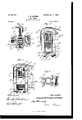
- Figure l is a fragmentary side elevation of a device embodying my invention.
- Fig. 2 is a section taken on line 2 2 of Fig. l.
- Fig. 3 is a section taken on line 3 3 of Fig. l.
- Fig. 4 is a section taken on line 4 4 of Fig. l.
- Fig. 5 is a section taken on line 5 5 of Fig. l.
- Fig. 6 is aside elevation of a modied form of a device embodying my invention.
- A indicates as a Whole a car-truck pedestal, B a car-axle provided with a journal b, and C an axle-box of familiar construction.
- the said pedestal is provided in the usual manner with a downwardly-opening recess, in which the axle-box is located.
- -C indicates a spring through which the truck is supported on the axle-box, said spring Fig. 7 is a section taken on line '7 7 of ⁇ being of the familiar spiral form and being interposed between the top of the axle-box and a cap C2, located over the box.
- the top wall of the axle-box is provided with an elevated annular rib or Iiange c', forming a re- Serial No. 722.130. (No model.)
- an annular groove c4 to receive the upper end of the spring, said groove holding the said upper end of the spring in proper position with respect to said cap.
- G F indicates a pivot-bar which is attached at its'ends to the lower part of the pedestal, at either side of the opening therein
- G G indicate two supporting-links which are pivotally engaged at their lower ends with the pivot-bar and are rigidly connected at their upper ends by a cross-bar G', by which said links are pivotally connected with the cap C2.
- Said links support the truck upon the axle-box and at the same time afford lateral movement of the'truck-frame with respect to the axle and wheels, so as to prevent excessive side pressure of the wheel-flanges against the rails, the pivotal connection of the links at their upper ends with the cap and at their lower ends with the truck-frame permitting the latter to swing or oscillate freely in a lateral direction Within the limited range of movement necessary for securing the desired results.
- Said journal-box is provided at its inner and outer ends with rigidly attached upright guide-standards c c, which have guiding engagement with the cap C2, preferably by means of apertured lugs c' c on the cap,which project from the inner and outer margins of said cap and are engaged by said guide-standards.
- Said guide-standards serve to hold the cap and the upper part'of the spring from lateral displacement with respect to the axlebox, while permittingthe cap to move vertically with respect to the axle-box as the spring expands and contracts under the action of the load thereon.
- the guide-standards arranged as described perform the important function of holding the cap and upper part of the spring at all times vertically over the axlebox, notwithstanding the horizontal inward or outward strain brought onthe cap by the supporting-links when the latter is thrown into an inwardly or outwardly inclined position in the lateral oscillating movements of th'e truck from its central or normal position.
- the guide-standards c c are extended IOO above the guide-lugs on the cap sufficiently far to engage the part of the pedestal above the cap, the upper ends of said standards constitnting stops, which by coming in contact with the outer or inner face of the truck prevent the truck from swinging or oscillating to a greater extent than is desirable or necessary.
- the supporting-links G G and the cross-bar G' are made integral with each other, the links and cross-bar thus forming an inverted stirrnp.
- the pivotal connection between said links and the cap is secured by the provision of a groove in the top surface of the cap, in which the cross-bar G rests, the lower surface of the cross-bar being rounded or made of parti-cylindric form and the groove in the cap of corresponding shape.
- the stirrup is made from a single fiat piece of metal bent in the direction of its least dimension into U form and corresponding in general proportions with the inner dimensions of the pedestal.
- the lower ends of the side pieces or links G G are increased in width laterally, and each is provided with an aperture which is semicircnlar in its lower part and which engages the pivot-bar F,which passes through said aperture.
- Said bar is rounded on its lower surface at its end portions which are engaged bythe links, said rounded portions titting the semicircular parts of the apertures of the links.
- The. links G G lit closely to the A sides of the axle-box, thereby serving as guides therefor and preventing horizontal movement of the axle-boxes in a lateral direction with respect to the car-axles.
- the pedestal A illustrated consists, mainly, of two like metal bars A4 A4 of inverted-U shape arranged parallel with each other and the inner faces of which constitute the walls vof the pedestal-opening, and the pivot-bar F has special features of construction adapting it for attachment to a pedestal so constructed.
- the said bars A4 A4 while rigidly attached to each other by rivets or the like, are separated from each other by a narrow space, and the lower extremities thereof extend below the l main parts of the truck-frame of which the said pedestal-bars A4 A4 are inserted in said recesses with the web f between the same,
- the central part of the pivot-bar is made relatively thin or light and of flanged form, as seen in the sectional view Fig. 3.
- the end portions of the pivot-bar are provided with depending transverse flanges f5 f5 at either side of the links G G, said lianges forming transverse grooves in which the lower ends of the links are located and by which the links are held from moving or shifting from their proper places on the bar.
- the openings or eyes in the lower ends of the links are made vertically deep enough to permit the removal and insertion therethrough of the enlarged end portions of the'pivot-bar outside of the said grooves.
- the truck-frame illustrated is an open trussframe made or built up of channel-bars, angle-bars, and plates and is like that shown in an application for patent, Serial No. 702,941, filed by Dwight Bruce Kennedy January 2l, 1899.
- Said truck-frame illustrated embraces an upper or compression member A4, the end of which is extended over the top of and downwardly at the outer side of the pedestal and which consists of an angle-bar having its web portion arranged vertically and inserted between the bars A4 A4 of the pedestal; a tension member which extends beneath the transom A5 of the truck, is deflected upwardly to the top of the pedestal, and extends over the top and downwardly at the outer side of the pedestal, with its end portion parallel with that of the compression member A', a horizontal tie-bar D, which is secured to the end of the transom and extends at its end to tlie inner vertical parts of the pedestal-bars A4; a vertical plate E, which abuts at its upper end against the compression member A
- the pedestal-bars A4 A4 preferably consist of angle-bars having their web portions a2 vertical and adjacent to each othcrand their IOO IIO
- flanges c located at the inner margins of said web portions and outwardly and inwardly directed, said flanges together forming the fiat walls of the pedestal-opening, as clearly shown in Figs. 2, 3, and 4.
- the parts should be so arranged as to permit the use of the largest possible spring, for the reason that a coiled spring of large diameter affords greater resiliency with the same strength, or, in other words, is less liable to become permanently set (or its limit of elasticity is liable to be reached) when greatly compressed by the jarring of the car under heavy loads.
- the feature of construction by which the upper ends of the said guide-standards are arranged in position to strike the pedestal, and thereby form stops to limit the lateral oscillation of the truck, is also an advantage, for the reason that the guide-bars thus arranged serve to positively limit the lateral movement both of the cap and the box itself with respect to the truck.
Landscapes
- Engineering & Computer Science (AREA)
- Mechanical Engineering (AREA)
- Handcart (AREA)
Description
0. 0 uw r. n. A d e t .n e t a D...
uw 9 5 N. J N.s, K2 H m mw... MT. .,Dum AB wcm S. .m m m 3. 8 .5, 6 4 ,6 .0. N
i Sheets-Sheet I.
(No Model.)
Patented Apr. 3, |900. S. W. MGMUNN.'
CAR T RUCK. '(Application med June 2s, 1899.)
2 Sheets-Sheet 2.
(No Model.)
Fa/fw livrrnn STATES PATEiwrl Enron.
SAMUEL VVOR'II-IINGTON MCMUNN, OF CHICAGO, ILLINOIS.
CAR-TRUCK.
SPECIFICATION 'forming part of Letters Patent No. 646,583, dated April 3, 1900.
Application filed rune 2c, 1899.
To a/Z whom, it may concern/.-
Be it known that I, SAMUEL WORTHINGTON MCMUNN, of Chicago, in the county of Cook and State of Illinois, have invented certain `new and useful Improvements in Car-Trucks; and I do hereby declare that the following is a full,clear, and exact description thereof, reference being had to the accompanying drawings, and to the letters of reference marked thereon, which form a part lof this specification.
This invention relates to improvements in railway-car-truck frames of that class in which the truck-frame is supported on jou rnal-boxes by means of supporting-links pivotally connected at their upper ends with the journalbox and at their lower ends to the truckt'rame, so as to permit lateral movement in oscillation of the frame with respect to the car-wheel axles, such lateral movement of the car-truck being intended to lessen or prevent excessive lateral pressure of the wheel-lian ges against the rails and consequent wear of the wheel-flanges.
The invention consists in the matters hereinafter set forth, and more particularly7 pointed out in the appendedclairns. l
In the drawings, Figure l is a fragmentary side elevation of a device embodying my invention. Fig. 2 is a section taken on line 2 2 of Fig. l. Fig. 3 is a section taken on line 3 3 of Fig. l. Fig. 4 is a section taken on line 4 4 of Fig. l. Fig. 5 is a section taken on line 5 5 of Fig. l. Fig. 6 is aside elevation of a modied form of a device embodying my invention. Fig. 6.
In the particular embodiment of my invention illustrated in said drawings, A indicates as a Whole a car-truck pedestal, B a car-axle provided with a journal b, and C an axle-box of familiar construction. The said pedestal is provided in the usual manner with a downwardly-opening recess, in which the axle-box is located. -C indicates a spring through which the truck is supported on the axle-box, said spring Fig. 7 is a section taken on line '7 7 of `being of the familiar spiral form and being interposed between the top of the axle-box and a cap C2, located over the box.` The top wall of the axle-box is provided with an elevated annular rib or Iiange c', forming a re- Serial No. 722.130. (No model.)
cess to receive the lower end of the spring C', whereby the same is held from lateral displacement. In the lower surface of the cap C2 is formed an annular groove c4 to receive the upper end of the spring, said groove holding the said upper end of the spring in proper position with respect to said cap.
F indicates a pivot-bar which is attached at its'ends to the lower part of the pedestal, at either side of the opening therein, and G G indicate two supporting-links which are pivotally engaged at their lower ends with the pivot-bar and are rigidly connected at their upper ends by a cross-bar G', by which said links are pivotally connected with the cap C2. Said links support the truck upon the axle-box and at the same time afford lateral movement of the'truck-frame with respect to the axle and wheels, so as to prevent excessive side pressure of the wheel-flanges against the rails, the pivotal connection of the links at their upper ends with the cap and at their lower ends with the truck-frame permitting the latter to swing or oscillate freely in a lateral direction Within the limited range of movement necessary for securing the desired results. Said journal-box is provided at its inner and outer ends with rigidly attached upright guide-standards c c, which have guiding engagement with the cap C2, preferably by means of apertured lugs c' c on the cap,which project from the inner and outer margins of said cap and are engaged by said guide-standards. Said guide-standards serve to hold the cap and the upper part'of the spring from lateral displacement with respect to the axlebox, while permittingthe cap to move vertically with respect to the axle-box as the spring expands and contracts under the action of the load thereon. The guide-standards arranged as described perform the important function of holding the cap and upper part of the spring at all times vertically over the axlebox, notwithstanding the horizontal inward or outward strain brought onthe cap by the supporting-links when the latter is thrown into an inwardly or outwardly inclined position in the lateral oscillating movements of th'e truck from its central or normal position.
For the purpose of limiting the lateral movement of the truck with respect to the axlebox the guide-standards c c are extended IOO above the guide-lugs on the cap sufficiently far to engage the part of the pedestal above the cap, the upper ends of said standards constitnting stops, which by coming in contact with the outer or inner face of the truck prevent the truck from swinging or oscillating to a greater extent than is desirable or necessary. The action of said standards in this respect is supplemented by stop projections, lugs, or fianges c3 c3 on the side faces of the axle-box, the same being so located as to come in contact with the side portions of the pedestal, at the inner or outer face of the said pedestals, at the same time that the upper ends of the guide-standards strike the upper part of the pedestal.
The supporting-links G G and the cross-bar G' are made integral with each other, the links and cross-bar thus forming an inverted stirrnp. The pivotal connection between said links and the cap is secured by the provision of a groove in the top surface of the cap, in which the cross-bar G rests, the lower surface of the cross-bar being rounded or made of parti-cylindric form and the groove in the cap of corresponding shape. The stirrup is made from a single fiat piece of metal bent in the direction of its least dimension into U form and corresponding in general proportions with the inner dimensions of the pedestal. The lower ends of the side pieces or links G G are increased in width laterally, and each is provided with an aperture which is semicircnlar in its lower part and which engages the pivot-bar F,which passes through said aperture. Said bar is rounded on its lower surface at its end portions which are engaged bythe links, said rounded portions titting the semicircular parts of the apertures of the links. The. links G G lit closely to the A sides of the axle-box, thereby serving as guides therefor and preventing horizontal movement of the axle-boxes in a lateral direction with respect to the car-axles.
The pedestal A illustrated consists, mainly, of two like metal bars A4 A4 of inverted-U shape arranged parallel with each other and the inner faces of which constitute the walls vof the pedestal-opening, and the pivot-bar F has special features of construction adapting it for attachment to a pedestal so constructed. The said bars A4 A4, while rigidly attached to each other by rivets or the like, are separated from each other by a narrow space, and the lower extremities thereof extend below the l main parts of the truck-frame of which the said pedestal-bars A4 A4 are inserted in said recesses with the web f between the same,
and the pivot-bar is secured to the said pcd estal-bars by bolts ffs, inserted through said parts. The outward-facing shoulders f f abut against the inner faces of the pedestalbars and, in connection with the bolts ff", serve to rigidly connect and hold from relative movement the lower ends of said pedes.
tal-bars. The upwardly-facing shoulders f4 f2 abut against the lower ends of the pedestalbars and serve to take the vertical strain due to the weight of the car and its load, which is transmitted to the axles through the medium of said pivot-bar and the links which connect it with the axle-box. Preferably the central part of the pivot-bar is made relatively thin or light and of flanged form, as seen in the sectional view Fig. 3. Preferably, also, the end portions of the pivot-bar are provided with depending transverse flanges f5 f5 at either side of the links G G, said lianges forming transverse grooves in which the lower ends of the links are located and by which the links are held from moving or shifting from their proper places on the bar. The openings or eyes in the lower ends of the links are made vertically deep enough to permit the removal and insertion therethrough of the enlarged end portions of the'pivot-bar outside of the said grooves.
The truck-frame illustrated is an open trussframe made or built up of channel-bars, angle-bars, and plates and is like that shown in an application for patent, Serial No. 702,941, filed by Dwight Bruce Kennedy January 2l, 1899. Said truck-frame illustrated embraces an upper or compression member A4, the end of which is extended over the top of and downwardly at the outer side of the pedestal and which consists of an angle-bar having its web portion arranged vertically and inserted between the bars A4 A4 of the pedestal; a tension member which extends beneath the transom A5 of the truck, is deflected upwardly to the top of the pedestal, and extends over the top and downwardly at the outer side of the pedestal, with its end portion parallel with that of the compression member A', a horizontal tie-bar D, which is secured to the end of the transom and extends at its end to tlie inner vertical parts of the pedestal-bars A4; a vertical plate E, which abuts at its upper end against the compression member A', is attached at its lower end to the tie-bar D, and atjts outer edge is inserted between and secured to the pedestal-bars A4 A4; a second vertical plate E', which is arranged in contact with and inside of the plate E and extends at its upper end between and is secured to the tension and compression members A and A3, and a top plate a, which is applied over the top of and connects the transom and the tension and compression members, these several parts being connected by rivets, as shown.
The pedestal-bars A4 A4 preferably consist of angle-bars having their web portions a2 vertical and adjacent to each othcrand their IOO IIO
flanges c located at the inner margins of said web portions and outwardly and inwardly directed, said flanges together forming the fiat walls of the pedestal-opening, as clearly shown in Figs. 2, 3, and 4.
An important advantage is gained by the employment of guide-standards located at the front and rear of the axle-box and engaging the cap in the manner described, for the reason that the guide-standards thus f arranged serve to properly guide and hold in place the cap, while aty the same time they do not in any way interfere with the spring and enable a spring to be used of the largest diameter possible, taking into consideration the space afforded between the links G G for said spring. It is important that the parts should be so arranged as to permit the use of the largest possible spring, for the reason that a coiled spring of large diameter affords greater resiliency with the same strength, or, in other words, is less liable to become permanently set (or its limit of elasticity is liable to be reached) when greatly compressed by the jarring of the car under heavy loads. The feature of construction by which the upper ends of the said guide-standards are arranged in position to strike the pedestal, and thereby form stops to limit the lateral oscillation of the truck, is also an advantage, for the reason that the guide-bars thus arranged serve to positively limit the lateral movement both of the cap and the box itself with respect to the truck. An advantage is also obtained from the use of the stop-anges on the sides of the axle-box in combination with the standards when both of these parts are located in position to strike the truck-frame at the same time, as hereinbefore described, for the reason that this construction avoids any tendency to tip or tilt the axle-box and insures an upright position thereof at such times as said parts may come in contact with the truck-frame in the lateral oscillation ofl ing-bolt of such strain and affording an eX-.
ceedingly strong and reliable connection between the parts.
ings in connection with an open-truss truckframe constructed of bars and plates, it is obvious that the same may be used in connection with any desired truck-'frame having a pedestal adapted to receive within the same the elements constituting'the device.
I claim as my inventionl. The combination with a car-truck and a journal-box of a supporting-spring, a cap, suspension-links pivotally connecting said cap with the trucks, and a guide arm or standard on the inner and outer ends of the journalbox and extended above the pedestal-opening and having guiding engagement withsaid cap.
2. The combination with a car-truck, and a journal-boX,ofa supporting-spring, a cap, suspension-links pivotally connecting said cap with the truck, and vertical guide-bars on the jou mal-box having guiding engagement with said cap,said guide-bars being extended above the cap in position for contact with the portion of the truck above said cap.
3. The combination with a car-truck, and a journal-boX,ofa supporting-spring, acap, suspension-links pivotally connected with said cap with the truck, upright guide-standards attached to the journal-box and having guiding engagement with said cap, the upper ends of said standards being located in position `for contact with the truck-frame, said box being provided with lateral iianges adapted for engagement with the side faces of the truck at the same time that the standards come in contact with the said truck.
4. The combination with a car-truck, provided with two parallel, U-shaped pedestalbars and a journal-box, of a pivot-bar attached at its ends to the lower ends of said pedestal-bars, said pivot-bar having at its IOO ends vertical webs which enter between the lenter between the lower ends of the pedestalbar and at either side of said webs with upwardly-facing shoulders and also with outwardly-facing shoulders, said upwardly and outwardly facing shoulders being adapted to bear against the end portions of the pedestalbars, links by which the truck is supported upon the journal-box, said links being engaged at their lower ends to the said pivotbar.
6. The combination with a car-truck hav- `ing two parallel U-shaped pedestal-bars, of a journal-box, a pivot-bar attached at its ends IIO to the lower ends of said pedestal-bars and links for supporting the truck from the journal-box, said links being provided at their lower ends with apertures to engage the pivotbar said pivot-bar being provided adjacent to its ends with semieylindric bearing-surfaces and with Jtransverse anges at either side thereof forming transverse grooves to receive the lower ends of the links, and said pivotbar being provided also, outside of said grooves, with vertical webs which enter between the said pedestal-bars, and at either side of said webs with upwardly-facing shoulders which bear against the lower ends of the pedestal-bars.
7. The combination with a car-truck pedestal and a journal box, of a supportingspring, a cap in contact with the upper end of said spring, said cap being provided with a transverse groove in its upper surface, supporting-links connected at their upper ends by a cross-bar which is made integral therewith and is provided with a'rounded lower surface engaging the grooves in said cap, a pivot-bar attached at its ends to the sides of the pedestal, and with which the lower ends of said links are engaged, and guide-standards on the inner and outer ends of, and extended above the journal-box through guideopenings in said cap.
S. The combination with a car-truck pedestal and a journal-box, of a pivot-bar attached at its ends to the sides of the pedestal, a su pporting-spring located over the journal-box, a cap provided with outwardly-projecting apertured lugs at its outer and inner margins, guide-standards on the outer and inner ends of the box passing through the apertures in said lugs, and supporting-links pivotally connected with said cap and with the pivot-bar.
9. The combination with a car-truck pedestal and a journal-box, of a pivot-bar attached at its ends to the sides of the pedestal, the supporting-spring of spirally-coiled form, a cap resting on' the top of the spring, said cap being provided on its upper surface with a bearing-groove and at its inner and outer sides with apertured lugs, supportingly connected at their upper ends by a cross-bar which engages said groove, said links being located closely adjacent to the sides of the pedestal, a pivot-bar attached at its ends to the sides of the pedestal and engaging the lower ends of said links and guide-standards on the inner and outer ends of the journal= box and extending upwardly therefrom in guiding engagement with the apertured lugs of said cap, the axle-box being constructed to fit closely between the links, and the spring being made of coiled form and of a diameter approximating the space between the said links.
In testimony that I claim the foregoing as my invention I affix my signature, in presence of witnesses, this 23d day of June, A. D. 1899.
SA UBL WOR'IIIING'I'ON MCMUNN.
Witnesses:
EDWIN S. WooDs, C. E. WILLIAMS, CHARLES W. HILLs.
Priority Applications (1)
| Application Number | Priority Date | Filing Date | Title |
|---|---|---|---|
| US72213099A US646583A (en) | 1899-06-28 | 1899-06-28 | Car-truck. |
Applications Claiming Priority (1)
| Application Number | Priority Date | Filing Date | Title |
|---|---|---|---|
| US72213099A US646583A (en) | 1899-06-28 | 1899-06-28 | Car-truck. |
Publications (1)
| Publication Number | Publication Date |
|---|---|
| US646583A true US646583A (en) | 1900-04-03 |
Family
ID=2715157
Family Applications (1)
| Application Number | Title | Priority Date | Filing Date |
|---|---|---|---|
| US72213099A Expired - Lifetime US646583A (en) | 1899-06-28 | 1899-06-28 | Car-truck. |
Country Status (1)
| Country | Link |
|---|---|
| US (1) | US646583A (en) |
-
1899
- 1899-06-28 US US72213099A patent/US646583A/en not_active Expired - Lifetime
Similar Documents
| Publication | Publication Date | Title |
|---|---|---|
| US2352693A (en) | Railway truck | |
| US560258A (en) | Truck for cars | |
| US646583A (en) | Car-truck. | |
| US773564A (en) | Car-truck. | |
| US717304A (en) | Car-truck. | |
| US800921A (en) | Car-truck. | |
| US2063739A (en) | Truck | |
| US1594644A (en) | Car truck | |
| US682273A (en) | Car-truck. | |
| US1077184A (en) | Car-truck. | |
| US566526A (en) | mcguibe | |
| US738773A (en) | Car-truck. | |
| US586482A (en) | Car-truck | |
| US2594079A (en) | Inboard railway truck | |
| US671844A (en) | Car-truck. | |
| US738840A (en) | Car-truck. | |
| US721715A (en) | Car-truck. | |
| US808062A (en) | Car-truck for motor propulsion and the like. | |
| US752799A (en) | Truck | |
| US625745A (en) | Passenger-car truck | |
| US566118A (en) | adams | |
| US1118621A (en) | Journal-box. | |
| US521205A (en) | Car-truck | |
| US1176938A (en) | Car-truck. | |
| US1000407A (en) | Car-truck. |