US6499352B2 - Pressure measuring cell - Google Patents
Pressure measuring cell Download PDFInfo
- Publication number
- US6499352B2 US6499352B2 US09/931,760 US93176001A US6499352B2 US 6499352 B2 US6499352 B2 US 6499352B2 US 93176001 A US93176001 A US 93176001A US 6499352 B2 US6499352 B2 US 6499352B2
- Authority
- US
- United States
- Prior art keywords
- pressure
- basic body
- measuring cell
- measuring
- measuring chamber
- Prior art date
- Legal status (The legal status is an assumption and is not a legal conclusion. Google has not performed a legal analysis and makes no representation as to the accuracy of the status listed.)
- Expired - Lifetime
Links
- 239000000919 ceramic Substances 0.000 claims abstract description 15
- 230000035515 penetration Effects 0.000 claims abstract description 8
- 230000001419 dependent effect Effects 0.000 claims abstract description 5
- 238000011156 evaluation Methods 0.000 claims abstract description 5
- 238000012545 processing Methods 0.000 claims abstract description 5
- 229910000679 solder Inorganic materials 0.000 claims description 27
- 238000001465 metallisation Methods 0.000 claims description 4
- 238000005476 soldering Methods 0.000 claims description 3
- 239000007788 liquid Substances 0.000 description 10
- PXHVJJICTQNCMI-UHFFFAOYSA-N Nickel Chemical compound [Ni] PXHVJJICTQNCMI-UHFFFAOYSA-N 0.000 description 2
- NEIHULKJZQTQKJ-UHFFFAOYSA-N [Cu].[Ag] Chemical compound [Cu].[Ag] NEIHULKJZQTQKJ-UHFFFAOYSA-N 0.000 description 2
- 238000009530 blood pressure measurement Methods 0.000 description 2
- 239000003990 capacitor Substances 0.000 description 2
- 230000000694 effects Effects 0.000 description 2
- 239000000463 material Substances 0.000 description 2
- 229910052751 metal Inorganic materials 0.000 description 2
- 239000002184 metal Substances 0.000 description 2
- 238000011144 upstream manufacturing Methods 0.000 description 2
- 229910000531 Co alloy Inorganic materials 0.000 description 1
- 229910000831 Steel Inorganic materials 0.000 description 1
- KGWWEXORQXHJJQ-UHFFFAOYSA-N [Fe].[Co].[Ni] Chemical compound [Fe].[Co].[Ni] KGWWEXORQXHJJQ-UHFFFAOYSA-N 0.000 description 1
- PCEXQRKSUSSDFT-UHFFFAOYSA-N [Mn].[Mo] Chemical compound [Mn].[Mo] PCEXQRKSUSSDFT-UHFFFAOYSA-N 0.000 description 1
- 230000032683 aging Effects 0.000 description 1
- 230000004888 barrier function Effects 0.000 description 1
- 229910052790 beryllium Inorganic materials 0.000 description 1
- 239000011248 coating agent Substances 0.000 description 1
- 238000000576 coating method Methods 0.000 description 1
- 239000011261 inert gas Substances 0.000 description 1
- 229910000833 kovar Inorganic materials 0.000 description 1
- 239000012528 membrane Substances 0.000 description 1
- 150000002739 metals Chemical class 0.000 description 1
- 238000000034 method Methods 0.000 description 1
- 229910052759 nickel Inorganic materials 0.000 description 1
- 230000000149 penetrating effect Effects 0.000 description 1
- 238000007789 sealing Methods 0.000 description 1
- 229920002545 silicone oil Polymers 0.000 description 1
- 239000010959 steel Substances 0.000 description 1
- 229910052715 tantalum Inorganic materials 0.000 description 1
- GUVRBAGPIYLISA-UHFFFAOYSA-N tantalum atom Chemical compound [Ta] GUVRBAGPIYLISA-UHFFFAOYSA-N 0.000 description 1
Images

Classifications
-
- G—PHYSICS
- G01—MEASURING; TESTING
- G01L—MEASURING FORCE, STRESS, TORQUE, WORK, MECHANICAL POWER, MECHANICAL EFFICIENCY, OR FLUID PRESSURE
- G01L9/00—Measuring steady of quasi-steady pressure of fluid or fluent solid material by electric or magnetic pressure-sensitive elements; Transmitting or indicating the displacement of mechanical pressure-sensitive elements, used to measure the steady or quasi-steady pressure of a fluid or fluent solid material, by electric or magnetic means
- G01L9/0041—Transmitting or indicating the displacement of flexible diaphragms
- G01L9/0072—Transmitting or indicating the displacement of flexible diaphragms using variations in capacitance
- G01L9/0075—Transmitting or indicating the displacement of flexible diaphragms using variations in capacitance using a ceramic diaphragm, e.g. alumina, fused quartz, glass
Definitions
- the invention relates to a ceramic pressure measuring cell.
- absolute-pressure measuring cells In pressure measurement, absolute-pressure, relative-pressure and differential-pressure measuring cells are used for example.
- a pressure to be measured is registered in absolute terms, i.e. as a pressure difference with respect to a vacuum.
- a relative-pressure measuring cell With a relative-pressure measuring cell, a pressure to be measured is picked up in the form of a pressure difference with respect to a reference pressure, for example a pressure which prevails where the sensor is located. In most applications, this is the atmospheric pressure at the place of use.
- a pressure to be measured is sensed in relation to a fixed reference pressure, the vacuum pressure, and in the case of relative-pressure measuring cells a pressure to be measured is sensed in relation to a variable reference pressure, for example the ambient pressure.
- a differential-pressure measuring cell senses a difference between a first pressure and a second pressure bearing on the measuring cell.
- a diaphragm connected to the basic body to form a measuring chamber
- an electromechanical transducer which serves the purpose of registering the deflection of the diaphragm and making it accessible for further evaluation and/or processing.
- Ceramic pressure measuring cells are advantageously used for pressure measurement, since ceramic pressure measuring cells have a measuring accuracy which is stable over a very long time.
- One reason for this is the strong ionic bonding of ceramic, which makes the material very durable and undergo virtually no aging in comparison with other materials, for example metals.
- Ceramic pressure measuring cells have so far usually been designed as what are known as dry absolute- or relative-pressure measuring cells.
- a dry pressure measuring cell is not filled with a liquid which transfers a pressure, for example into a measuring chamber of the pressure measuring cell.
- the pressure measuring cell is restrained at an outer edge in a housing, with a seal interposed.
- a pressure to be measured is fed to the diaphragm through an opening in the housing or a process connection connected to the generally metallic housing.
- a pressure to be measured can only be fed directly to such measuring cells.
- the use for example of an upstream diaphragm seal is usually not envisaged in the case of these pressure measuring cells.
- a soldered-in small pressure tube provides an elastomer-free, hermetically sealed joint for the pressure measuring cell.
- the small pressure tube and the measuring chamber, and also a pressure source, for example a diaphragm seal, arranged upstream of the small pressure tube, are filled with a liquid.
- the required volume of liquid is as identical as possible from one measuring cell to the other.
- Pressure measuring cells which serve for measuring a pressure difference typically have two identically formed halves, which are each connected to a pressure source. In the case of these pressure measuring cells, it is important not only that each half requires as small a volume of liquid as possible but also that the required volume of liquid in both halves is as identical as possible. One reason for this is that different volumes result in a different change in volume in the two halves when there is a change in temperature. This can lead to considerable temperature-dependent measuring errors.
- the invention comprises a ceramic pressure measuring cell with
- a diaphragm connected to the basic body to form a measuring chamber
- an electromechanical transducer which serves the purpose of registering the deflection of the diaphragm and making it accessible for further evaluation and/or processing
- a mechanical stop by which a depth of penetration of the small pressure tube into the basic body is fixed.
- the stop is a shoulder which is formed onto the small pressure tube, extends radially outward and rests on an annular face of the basic body surrounding the bore.
- the bore has a portion facing the measuring chamber and a portion facing away from the measuring chamber, the portion facing the measuring chamber having an inside diameter which is smaller than an outside diameter of the small pressure tube and is an inside diameter of the portion facing away from the measuring chamber, and between the two portions there is an annular face, which forms the stop and on which the small pressure tube rests with an annular end face.
- the solder is a glass solder.
- the solder is a metallic hard solder and the ceramic basic body has a pre-metallization at a connecting point between the basic body and the small pressure tube.
- the solder is an active hard solder.
- the stop achieves the effect that a depth of penetration of the small pressure tube into the basic body is precisely predetermined.
- a volume which displaces the small pressure tube in the bore in the basic body can be established in a reproducible manner.
- the internal volume of the pressure measuring cell can consequently be established in a reproducible manner.
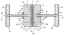
- FIG. 1 shows a section through a pressure measuring cell according to the invention.
- FIG. 1 shows a section through a ceramic pressure measuring cell according to the invention. It is designed as a differential-pressure measuring cell and has a first basic body 1 and a second basic body 3 . Arranged between the first basic body 1 and the second basic body 3 is a diaphragm 5 . The diaphragm 5 is connected to the first basic body 1 to form a first measuring chamber 7 and is connected to the second basic body 3 to form a second measuring chamber 9 .
- the diaphragm 5 and the first and second basic bodies 1 , 3 consist of ceramic.
- the first and second basic bodies 1 , 3 are each connected to the diaphragm 5 by a joint 11 , for example by means of an active hard solder, such as for example a zirconium-iron-titanium-beryllium solder, at a respectively outer annular edge.
- an active hard solder such as for example a zirconium-iron-titanium-beryllium solder
- a first pressure p 1 prevails in the first measuring chamber 7 and a second pressure p 2 prevails in the second measuring chamber 9 .
- the deflection of the diaphragm 5 depends on a pressure to be measured, which corresponds to the difference between the first pressure p 1 and the second pressure p 2 .
- the first basic body 1 For feeding in the pressure, the first basic body 1 has a continuous bore 13 , which leads into the measuring chamber 7 and into which a first small pressure tube 15 is fitted. During operation, the first pressure p 1 is fed to the measuring chamber 7 via the first small pressure tube 15 .
- the second basic body 3 has for feeding in the pressure a continuous bore 17 , which leads into the measuring chamber 9 and into which a second small pressure tube 19 is fitted. During operation, the second pressure p 2 is fed to the measuring chamber 9 via the small pressure tube 19 .
- the small pressure tubes 15 , 19 are each connected to a diaphragm seal 21 , 23 .
- the diaphragm seals 21 , 23 each have a separating diaphragm 25 , 27 , which in each case covers a chamber 29 , 31 .
- the first pressure p 1 acts from the outside on the separating diaphragm 25 and the second pressure p 2 acts from the outside on the second separating diaphragm 27 .
- the chambers 29 , 31 , the small pressure tubes 15 , 19 and the measuring chambers 7 , 9 are filled with a liquid which is as incompressible as possible, for example a silicone oil.
- the liquid has the effect of transferring the first and second pressures p 1 , p 2 acting on the separating membranes 25 , 27 from the outside into the assigned first and second measuring chambers 7 , 9 , respectively, where they act on in each case one side of the diaphragm 5 .
- a mechanical stop 33 is provided, fixing a depth of penetration of the first small pressure tube 15 into the basic body 1 .
- a mechanical stop 35 is also provided, fixing a depth of penetration of the second small pressure tube 19 into the second basic body 3 .
- the depth of penetration of a small pressure tube can be fixed by means of a stop in various ways. Therefore, two configurations of a mechanical stop are represented in FIG. 1 by way of example. Other forms of a mechanical stop which prevent further penetration of the small pressure tube by means of a mechanical barrier can likewise be used.
- the stop 33 comprises a shoulder 37 which is formed onto the small pressure tube 15 , extends radially outward and rests on an annular face of the basic body surrounding the bore 13 and facing away from the diaphragm.
- the bore 17 has a portion 39 facing the measuring chamber and a portion 41 facing away from the measuring chamber.
- the portion 39 facing the measuring chamber has an inside diameter which is smaller than an outside diameter of the small pressure tube 19 and is an inside diameter of the portion 41 facing away from the measuring chamber.
- the small pressure tube 19 rests on the annular face with an annular end face.
- the small pressure tubes 15 , 19 consist of metal, for example of a high-grade steel, tantalum or a nickel-iron-cobalt alloy, as is commercially available for example under the product name Kovar, and have been soldered into the respective bore 13 , 17 in a pressure-resistant and gastight manner by means of a solder 43 , 45 .
- the solder 43 has been applied in an annular form between the shoulder 37 and the first basic body 1 .
- the solder 45 has been introduced into an annular-cylindrical gap between the small pressure pipe 19 and the bore 17 .
- the solder could also have been introduced into an annular-cylindrical gap between the small pressure tube 15 and the bore 13 .
- solder 43 , 45 are a glass solder, a metallic hard solder or an active hard solder, for example a silver-copper active hard solder.
- the ceramic basic body is provided at a connecting point between the basic body and the small pressure tube with a pre-metallization, for example of molybdenum-manganese with a nickel coating.
- a pre-metallization for example of molybdenum-manganese with a nickel coating.
- solder is a silver-copper hard solder applied to the pre-metallization.
- the soldering operation takes place for example in an oven under a vacuum or in an inert-gas atmosphere.
- the stops 33 , 35 offer the advantage during soldering that the required amount of solder can be apportioned and positioned very accurately, since the position of the respective small pressure tube 15 , 19 in the respective bore 13 , 17 is precisely fixed. As a result, a very high-grade, and consequently unrestrictedly gastight and mechanically stable, in particular very pressure-resistant, connection is made possible.
- the pressure measuring cells can therefore withstand very high pressures, for example 40,000 kPa (400 bar).
- the diaphragm 5 undergoes a deflection, which depends on the pressure to be measured, here the difference between the first pressure p 1 and the second pressure p 2 .
- the deflection is registered by means of an electromagnetic transducer.
- the electromechanical transducer has an electrode 47 which has been applied to an inner surface of the first basic body 1 facing the diaphragm and, together with a counterelectrode 49 applied to the diaphragm 5 , forms a capacitor, the capacitance of which is a measure of the deflection of the diaphragm 5 .
- the counterelectrode 49 adjoins the joint 11 with its outer edge in an electrically conducting manner and is preferably connected via the joint 11 to ground or to a fixed reference potential.
- an identically constructed electromechanical transducer is preferably provided in the second measuring chamber 9 , as represented in FIG. 1 .
- the stop 33 offers the further advantage that there is no possibility of the small pressure tube 15 penetrating into the measuring chamber 7 and producing a short circuit there between the electrode 47 and the counterelectrode 49 . Such a short circuit would lead to a total failure of the measuring cell.
- the basic body 1 has a continuous bore, to which a metallic contact pin 51 has been led.
- the electrode 47 is electrically connected by means of the contact pin 51 for measuring the capacitance.
- a first end of the contact pin 51 is connected in an electrically conducting manner to the electrode 47 .
- a remaining second end protrudes out of the basic body 1 and is led in the exemplary embodiment shown to an electronic circuit 53 , arranged on the basic body 1 .
- the electronic circuit 53 converts the changes in capacitance of the capacitor into an electrical output signal, for example into a correspondingly changing electrical voltage.
- the output signal is available for further processing and/or evaluation via connection lines 55 .
- the second basic body 3 likewise has such a plated-through hole, via which the electromechanical transducer arranged in the second measuring chamber 9 is connected to an electronic circuit 53 .
- the difference between the capacitances of the two electromechanical transducers is preferably determined and the differential pressure is ascertained from it.
- a differential-pressure measuring cell is represented.
- a relative-pressure or absolute-pressure measuring cell may also be constructed in an analogous way.
- the first pressure p 1 would correspond for example to a pressure to be measured and the second pressure p 2 would correspond to a reference pressure, to which the pressure to be measured is related.
- the second measuring chamber 9 may also be provided with a reference-pressure feed, for example a bore which penetrates the basic body 3 and through which a pressure prevailing in the ambience acts on the second measuring chamber 9 .
- An absolute-pressure measuring cell is obtained in an analogous way, by evacuating and hermetically sealing the second measuring chamber 9 , instead of connecting it to a diaphragm seal 23 .
Landscapes
- Chemical & Material Sciences (AREA)
- Engineering & Computer Science (AREA)
- Ceramic Engineering (AREA)
- Physics & Mathematics (AREA)
- General Physics & Mathematics (AREA)
- Measuring Fluid Pressure (AREA)
- Optical Measuring Cells (AREA)
Applications Claiming Priority (3)
| Application Number | Priority Date | Filing Date | Title |
|---|---|---|---|
| DE10050300.4 | 2000-10-10 | ||
| DE10050300A DE10050300A1 (de) | 2000-10-10 | 2000-10-10 | Druckmeßzelle |
| DE10050300 | 2000-10-10 |
Publications (2)
| Publication Number | Publication Date |
|---|---|
| US20020040605A1 US20020040605A1 (en) | 2002-04-11 |
| US6499352B2 true US6499352B2 (en) | 2002-12-31 |
Family
ID=7659377
Family Applications (1)
| Application Number | Title | Priority Date | Filing Date |
|---|---|---|---|
| US09/931,760 Expired - Lifetime US6499352B2 (en) | 2000-10-10 | 2001-08-20 | Pressure measuring cell |
Country Status (6)
| Country | Link |
|---|---|
| US (1) | US6499352B2 (de) |
| EP (1) | EP1325295B1 (de) |
| AT (1) | ATE374933T1 (de) |
| AU (1) | AU2001287692A1 (de) |
| DE (2) | DE10050300A1 (de) |
| WO (1) | WO2002031460A1 (de) |
Cited By (2)
| Publication number | Priority date | Publication date | Assignee | Title |
|---|---|---|---|---|
| US6752021B2 (en) * | 2001-07-14 | 2004-06-22 | Endress + Hauser Gmbh & Co. Kg | Relative pressure measuring instrument |
| US20080035227A1 (en) * | 2005-07-14 | 2008-02-14 | Pdc Facilities, Inc. | Liner for a flow meter |
Families Citing this family (4)
| Publication number | Priority date | Publication date | Assignee | Title |
|---|---|---|---|---|
| DE102004033813B4 (de) * | 2004-07-12 | 2010-04-08 | Endress + Hauser Gmbh + Co. Kg | Druckmessgerät |
| DE102004033812B4 (de) * | 2004-07-12 | 2010-01-28 | Endress + Hauser Gmbh + Co. Kg | Druck- oder Differenzdruckaufnehmer |
| DE102011004729A1 (de) | 2011-02-25 | 2012-08-30 | Endress + Hauser Gmbh + Co. Kg | Keramische Druckmesszelle und Drucksensor mit keramischer Druckmesszelle |
| DE102013220735A1 (de) * | 2013-10-14 | 2015-04-16 | Vega Grieshaber Kg | Messanordnung mit einer keramischen Messzelle |
Citations (5)
| Publication number | Priority date | Publication date | Assignee | Title |
|---|---|---|---|---|
| US4370890A (en) | 1980-10-06 | 1983-02-01 | Rosemount Inc. | Capacitive pressure transducer with isolated sensing diaphragm |
| DE3312385A1 (de) | 1982-04-09 | 1983-10-20 | Fuji Electric Co., Ltd., Kawasaki, Kanagawa | Druckmessvorrichtung |
| US4754365A (en) | 1987-06-15 | 1988-06-28 | Fischer & Porter Company | Differential pressure transducer |
| DE3821693A1 (de) | 1987-11-09 | 1989-05-18 | Schwerin Bezirkskrankenhaus | Kapazitiver druckwandler und verfahren zur herstellung dieses druckwandlers |
| US5157972A (en) | 1991-03-29 | 1992-10-27 | Rosemount Inc. | Pressure sensor with high modules support |
Family Cites Families (2)
| Publication number | Priority date | Publication date | Assignee | Title |
|---|---|---|---|---|
| US4542435A (en) * | 1984-03-29 | 1985-09-17 | General Signal Corporation | Pressure transducer and mounting |
| DE4207949C1 (en) * | 1992-03-10 | 1993-04-01 | Mannesmann Ag, 4000 Duesseldorf, De | Capacitative differential pressure sensor of glass-silicon@ type - has second pressure supply channel communicating with first but offset in covering plate |
-
2000
- 2000-10-10 DE DE10050300A patent/DE10050300A1/de not_active Withdrawn
-
2001
- 2001-08-17 AT AT01967282T patent/ATE374933T1/de not_active IP Right Cessation
- 2001-08-17 WO PCT/EP2001/009492 patent/WO2002031460A1/de not_active Ceased
- 2001-08-17 EP EP01967282A patent/EP1325295B1/de not_active Expired - Lifetime
- 2001-08-17 DE DE50113092T patent/DE50113092D1/de not_active Expired - Lifetime
- 2001-08-17 AU AU2001287692A patent/AU2001287692A1/en not_active Abandoned
- 2001-08-20 US US09/931,760 patent/US6499352B2/en not_active Expired - Lifetime
Patent Citations (6)
| Publication number | Priority date | Publication date | Assignee | Title |
|---|---|---|---|---|
| US4370890A (en) | 1980-10-06 | 1983-02-01 | Rosemount Inc. | Capacitive pressure transducer with isolated sensing diaphragm |
| DE3312385A1 (de) | 1982-04-09 | 1983-10-20 | Fuji Electric Co., Ltd., Kawasaki, Kanagawa | Druckmessvorrichtung |
| US4754365A (en) | 1987-06-15 | 1988-06-28 | Fischer & Porter Company | Differential pressure transducer |
| DE3820418A1 (de) | 1987-06-15 | 1988-12-29 | Fischer & Porter Co | Differenzdruckwandler |
| DE3821693A1 (de) | 1987-11-09 | 1989-05-18 | Schwerin Bezirkskrankenhaus | Kapazitiver druckwandler und verfahren zur herstellung dieses druckwandlers |
| US5157972A (en) | 1991-03-29 | 1992-10-27 | Rosemount Inc. | Pressure sensor with high modules support |
Cited By (3)
| Publication number | Priority date | Publication date | Assignee | Title |
|---|---|---|---|---|
| US6752021B2 (en) * | 2001-07-14 | 2004-06-22 | Endress + Hauser Gmbh & Co. Kg | Relative pressure measuring instrument |
| US20080035227A1 (en) * | 2005-07-14 | 2008-02-14 | Pdc Facilities, Inc. | Liner for a flow meter |
| US7819139B2 (en) | 2005-07-14 | 2010-10-26 | Pdc Facilities, Inc. | Liner for a flow meter |
Also Published As
| Publication number | Publication date |
|---|---|
| DE50113092D1 (de) | 2007-11-15 |
| DE10050300A1 (de) | 2002-04-11 |
| EP1325295A1 (de) | 2003-07-09 |
| AU2001287692A1 (en) | 2002-04-22 |
| EP1325295B1 (de) | 2007-10-03 |
| ATE374933T1 (de) | 2007-10-15 |
| US20020040605A1 (en) | 2002-04-11 |
| WO2002031460A1 (de) | 2002-04-18 |
Similar Documents
| Publication | Publication Date | Title |
|---|---|---|
| US6715356B2 (en) | Pressure sensor having metallic diaphragm seal mount | |
| US7819014B1 (en) | Capacitive gage pressure sensor with vacuum dielectric | |
| JP4044307B2 (ja) | 圧力センサ | |
| US7360428B2 (en) | Capacitive pressure measuring cell with a membrane bed | |
| US7401522B2 (en) | Pressure sensor using compressible sensor body | |
| US10473546B2 (en) | Hermetic pressure sensor having a bending part | |
| JP3325879B2 (ja) | 相対圧センサ | |
| US8443676B2 (en) | Pressure sensor for hydraulic media in motor vehicle brake systems | |
| US7181974B2 (en) | Moisture-protected pressure sensor | |
| WO2003093779A1 (en) | Sensor package | |
| CN107667279A (zh) | 压力感测设备 | |
| US6499352B2 (en) | Pressure measuring cell | |
| US5034848A (en) | Low pressure sensor | |
| JP2007327976A (ja) | 圧力センサ | |
| US6425291B1 (en) | Relative-pressure sensor having a gas-filled bellows | |
| US7073400B2 (en) | Sensor for measuring pressure in a sealed volume | |
| EP0775303A1 (de) | Druckwandler | |
| JPH0650270B2 (ja) | 高圧用圧力検出器 | |
| CN115165172A (zh) | 一种介质隔离的应变片式绝压压力传感器 | |
| CN121475507A (zh) | 一种薄膜压阻式压力传感器、标定系统及测量方法 | |
| JPH02262032A (ja) | 絶対圧型半導体圧力センサ | |
| WO2015104600A1 (en) | A sensor for measuring fluid variables in a corrosive environment | |
| JPH04242133A (ja) | 静電容量式差圧検出器 |
Legal Events
| Date | Code | Title | Description |
|---|---|---|---|
| AS | Assignment |
Owner name: ENDRESS + HAUSER GMBH + CO., GERMANY Free format text: ASSIGNMENT OF ASSIGNORS INTEREST;ASSIGNORS:BANHOLZER, KARLHEINZ;FLOGEL, KARL;HEGNER, FRANK;AND OTHERS;REEL/FRAME:012112/0534 Effective date: 20010809 |
|
| STCF | Information on status: patent grant |
Free format text: PATENTED CASE |
|
| FEPP | Fee payment procedure |
Free format text: PAYOR NUMBER ASSIGNED (ORIGINAL EVENT CODE: ASPN); ENTITY STATUS OF PATENT OWNER: LARGE ENTITY |
|
| FPAY | Fee payment |
Year of fee payment: 4 |
|
| FPAY | Fee payment |
Year of fee payment: 8 |
|
| FPAY | Fee payment |
Year of fee payment: 12 |