US6499606B1 - Cross-flow filter membrane and method of manufacturing it - Google Patents
Cross-flow filter membrane and method of manufacturing it Download PDFInfo
- Publication number
- US6499606B1 US6499606B1 US09/627,068 US62706800A US6499606B1 US 6499606 B1 US6499606 B1 US 6499606B1 US 62706800 A US62706800 A US 62706800A US 6499606 B1 US6499606 B1 US 6499606B1
- Authority
- US
- United States
- Prior art keywords
- fluid
- membrane
- treated
- separator layer
- flow
- Prior art date
- Legal status (The legal status is an assumption and is not a legal conclusion. Google has not performed a legal analysis and makes no representation as to the accuracy of the status listed.)
- Expired - Lifetime
Links
Images


Classifications
-
- B—PERFORMING OPERATIONS; TRANSPORTING
- B01—PHYSICAL OR CHEMICAL PROCESSES OR APPARATUS IN GENERAL
- B01D—SEPARATION
- B01D63/00—Apparatus in general for separation processes using semi-permeable membranes
- B01D63/06—Tubular membrane modules
- B01D63/066—Tubular membrane modules with a porous block having membrane coated passages
-
- B—PERFORMING OPERATIONS; TRANSPORTING
- B01—PHYSICAL OR CHEMICAL PROCESSES OR APPARATUS IN GENERAL
- B01D—SEPARATION
- B01D63/00—Apparatus in general for separation processes using semi-permeable membranes
- B01D63/06—Tubular membrane modules
- B01D63/061—Manufacturing thereof
-
- B—PERFORMING OPERATIONS; TRANSPORTING
- B01—PHYSICAL OR CHEMICAL PROCESSES OR APPARATUS IN GENERAL
- B01D—SEPARATION
- B01D2313/00—Details relating to membrane modules or apparatus
- B01D2313/08—Flow guidance means within the module or the apparatus
-
- B—PERFORMING OPERATIONS; TRANSPORTING
- B01—PHYSICAL OR CHEMICAL PROCESSES OR APPARATUS IN GENERAL
- B01D—SEPARATION
- B01D2315/00—Details relating to the membrane module operation
- B01D2315/10—Cross-flow filtration
Definitions
- the present invention relates to the technical field of separating out molecules or particles by implementing separator elements generally known as “membranes” and made out of inorganic materials and constituted by a rigid porous support having at least one flow channel for a fluid medium, with at least one separator layer being deposited on the surface thereof, the nature and the morphology of the layer being adapted to separate out molecules or particles contained in the fluid medium for treatment.
- separator elements generally known as “membranes” and made out of inorganic materials and constituted by a rigid porous support having at least one flow channel for a fluid medium, with at least one separator layer being deposited on the surface thereof, the nature and the morphology of the layer being adapted to separate out molecules or particles contained in the fluid medium for treatment.
- the invention relates to making separator layers forming parts of inorganic membranes.
- a particularly advantageous application of the invention lies in the fields of nanofiltration, ultrafiltration, microfiltration, filtration, and reverse osmosis.
- a membrane is defined by associating a porous support made of inorganic material, such as a ceramic, with one or more separator layers of inorganic material deposited on the surface of each flow channel and connected to one another and to the support by sintering.
- the function of the layers is to separate out molecular or particulate species, while the function of the support is to provide mechanical strength enabling thin layers to be made.
- the support provides mechanical strength without contributing to the hydraulic resistance of the membrane, while the separator layer defines permeability without contributing to mechanical strength.
- the rigid porous support is elongate in shape having a right cross-section that is polygonal or circular.
- the porous support is arranged to include at least one channel, and preferably a series of channels that are parallel to one another and to the longitudinal axis of the porous support, each channel being in the form of a cylinder.
- the channels communicate with an inlet chamber for the fluid medium to be treated, and at the other end they communicate with an outlet chamber.
- each channel is covered in at least one separator layer serving to separate out molecules or particles contained in the fluid medium flowing along the inside of the channels in a given direction form one end of the channels to the other.
- a sieving effect such a membrane separates out molecular or particulate species from the substance to be treated, insofar as all particles or molecules of diameter larger than the pores in the membrane are stopped.
- fluid transfer takes place through the separator layer, and then the fluid spreads into the pores of the support and reaches the outside surface of the porous support.
- the portion of the fluid for treatment that passes through the separator layer and the porous support is referred to as the “permeate” and it is recovered by a collector chamber surrounding the membrane.
- the porous support is in the form of a block having at least one channel, and generally a series of superposed channels formed therein, each channel having a right cross-section that is polygonal, and generally rectangular.
- the surface of each channel is covered in at least one separator layer.
- the fluid to be treated flows at high speed over the surfaces of the channels so as to generate shear stress which redisperses the matter deposited on said surfaces. Fluid friction thus arises on the surfaces of the channels and causes head loss which varies linearly as a function of channel length. This head loss depends on dimensional parameters such as the length of the membrane, its hydraulic diameter, and experimental parameters such as the flow speed, the viscosity, and the density of the fluid to be treated.
- U.S. Pat. No. 4,105,547 describes a cross-flow filter device implementing a system for compensating longitudinal head loss.
- Such a system consists in causing the permeate to flow tangentially outside the membrane in the same direction as the fluid to be treated flows tangentially inside the channels.
- the head loss in the permeate flow is identical to that of the fluid to be treated. Compensation thus occurs between the two head losses such that the transfer pressure is the same at all points along the channels.
- Such a device presents the drawback of requiring a permeate recirculation loop to be implemented, thereby considerably complicating manufacture of such devices and increasing the energy cost associated with operating the additional loop.
- European patent application EP 0 870 534 proposes a macroporous support whose external porosity is modified so as to a porosity gradient to appear along the support.
- the porosity gradient gives rise to a permeability gradient. Because of the pressure variation, the flow of permeate passing through the membrane becomes constant.
- the diameter of the pores on a transverse right-section of such a support increases and then diminishes at its periphery, so a risk appears of molecules or particles accumulating. Such accumulation can lead to the support being destroyed.
- the porosity is reduced solely on the outer ring of the porous support. Thus, internally the porosity of the support is not reduced.
- the pressure inside the channel decreases in the flow direction of the fluid to be treated.
- the permeate spreads out in the internal pores and flows towards the outside by seeking out zones requiring least energy. The permeate thus flows mainly via the portion of the support having the greatest porosity. Under such conditions, the porosity gradient implemented in this way leads to a permeate flow arising that is non-uniform along the length of the membrane.
- the invention thus seeks to remedy the drawbacks specified above by proposing a cross-flow filter membrane adapted to obtain a permeate flow that is substantially identical along the length of the membrane and that does not present a fragile zone in which the species of the fluid to be treated accumulate because they are retained by the membrane.
- the membrane of the invention comprises an inorganic rigid porous support defining at least one flow channel for the fluid to be treated, the fluid flowing in a given direction, the surface of the channel being covered by at least one separator layer for separating the fluid to be treated.
- the separator layer has a thickness gradient which decreases in the flow direction of the fluid to be treated.
- the invention also provides a method of making a membrane for cross-flow filtering of a fluid to be treated.
- a method consists in covering the surface of the channel in at least one separator layer presenting a thickness gradient that decreases in the flow direction of the fluid to be treated.
- FIG. 1 is a cross-section of an embodiment of a membrane in accordance with the invention.
- FIG. 2 is a longitudinal section view of a membrane seen substantially on lines II—II of FIG. 1 .
- FIG. 3 is a longitudinal section view of another embodiment of a membrane in accordance with the invention.
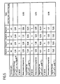
- FIGS. 4 and 5 are tables giving experimental measurements respectively for a prior art membrane and for a membrane of the invention.
- the filter membrane 1 of the invention is adapted to separate or filter out molecules or particles contained in various kinds of fluid medium, preferably liquids, and optionally containing a solid phase.
- the filter membrane 1 is of the tubular type.
- the filter membrane 1 has an inorganic rigid porous support 2 made of a material whose transfer resistance is adapted to the separation that is to be performed.
- the porous support 2 is made of inorganic material, such as a metal oxide, carbon, or metal.
- the porous support 2 is elongate in shape, extending along a central longitudinal axis A.
- the porous support 2 has a polygonal right cross-section or, as shown in FIGS. 1 and 2, a circular cross-section.
- the porous support 2 thus presents an outside surface 21 that is circularly cylindrical.
- the porous support 2 is arranged to have at least one channel, and in the example shown it has three channels 3 extending parallel to the axis A of the support.
- Each of the channels 3 has a surface covered in at least one separator layer 4 that is to come into contact with the fluid medium to be treated, said medium flowing inside the channels 3 in a flow direction represented by arrows f serving to define an inlet E and an outlet S for such a membrane.
- the nature of the separator layer(s) 4 is/are selected as a function of the separation or filter power that is to be obtained and as a function of ability to form an intimate bond with the porous support 2 so that the pressure from the liquid medium is transmitted to the porous support 2 .
- the layer(s) can be deposited, for example, from suspensions containing at least one metal oxide and conventionally used in the production of inorganic filter elements.
- the layer(s) is/are subjected to a sintering operation after drying for the purposes of consolidation and bonding with the porous support 2 , and between layers when there are two or more layers.
- a portion of the fluid medium passes through the separator layer 4 and the porous support 2 such that this treated portion of the fluid, referred to as “permeate”, flows out through the outside surface 21 of the porous support.
- the separator layer 4 is of thickness e that presents a gradient which decreases along the flow direction f of the fluid to be treated.
- the thickest portion of the layer 4 is present at the inlet E of the membrane, while the thinnest portion of the layer 4 is situated at the outlet S of the membrane.
- the flow of permeate passing through said layer 4 and the porous support 2 is constant along the membrane, providing the thickness e of the layer 4 varies in proportion to the pressure.
- the pressure of the fluid to be treated presents a gradient which decreases in the fluid flow direction f, i.e. from the inlet E to the outlet S of the membrane.
- the thickness gradient of the layer is therefore selected in such a manner as to obtain a constant permeate flow rate over the entire length of the membrane.
- the separator layer 4 has a thickness gradient that decreases in substantially continuous manner in the flow direction f of the fluid to be treated. It should be observed in the figures that the ratios of dimensions between the separator layer 4 and the porous support 2 are not true, with the scale of the separator layer 4 being exaggerated so as to illustrate the invention.
- the separator layer 4 has a thickness gradient that diminishes in steps P i in the flow direction f of the fluid to the treated.
- the separator layer 4 has four steps P 1 to P 4 of thickness that decreases in the flow direction of the fluid to be treated.
- the steps P 1 to P 4 of the separator layer 4 are preferably all of substantially identical length in the flow direction.
- the layer 4 possesses thickness that is substantially constant along each of the steps P 1 to P 4 .
- the thickness of the layer in step P 4 which is closest to the inlet E is greater than the thickness of the layer in the adjacent step P 3 , and so on for the other consecutive steps. It should be observed that it can be envisaged for the layer in each step P 1 to P 4 to be of a thickness that is not constant but that decreases progressively in the flow direction f, with a discontinuity in layer thickness appearing at the junction zones between consecutive steps.
- the above-described examples relate to a membrane made up of channels each of which has a cylindrical shape of right cross-section that is substantially ovoid.
- the invention can be implemented with membranes having one or more channels of a variety of shapes and of various shapes.
- the invention can be applied to a membrane having at least one channel 3 of polygonal cross-section arranged in a porous block so as to constitute a membrane of the plane type.
- the porous support 2 has a series of superposed channels 3 each presenting a right cross-section that is rectangular and having its walls covered in a separator layer.
- the invention also provides a method of making a filter membrane 1 of the kind described above.
- the description below relates to a method for making a membrane of the kind shown in FIG. 3 .
- Such a method consists in subdividing each channel 3 into a series of segments P i of substantially equal length, e.g. four segments P 1 to P 4 in the example shown.
- the surface of each channel 3 is then covered in a separator layer 4 by implementing as many deposition operations as there are segments P i .
- the layer 4 is obtained by four successive deposition operations using a suspension that includes various components that are generally in the form of grains.
- the thickness of the deposit is controlled by parameters relating to suspension concentration and to time of contact between the suspension and the porous support 2 .
- the deposits are made on the surfaces of the channels 3 starting from the inlet end E, with the length of channel subjected to deposition being reduced by one segment for each successive deposition operation.
- a suspension is initially deposited on all four segments P 1 to P 4 of the membrane.
- a second deposition operation is performed on segments P 4 to P 2 , a third operation on segments P 4 and P 3 , and a fourth operation on segment P 4 .
- a separator layer 4 is thus obtained which presents a thickness gradient that decreases in steps from one end E to the other end S of the membrane.
- a membrane of the invention can be manufactured by another technique which consists in placing the porous support 2 vertically and in filling the channels 3 with a suspension for depositing the separator layer 4 that is to be obtained. Given the vertical disposition of the porous support 2 , the pressure in the bottom portion of the support is different from that in the top portion by an amount that is proportional to the height of the porous support 2 . The deposit made in this way thus takes up a “billiard cue” appearance, such that the thickness of the separator layer 4 increases starting from the top of the porous support. It is recalled that the thickness of the deposited separator layer 4 depends on contact time between the porous support 2 and the suspension.
- a filter membrane having a separator layer with a thickness gradient can be manufactured by deposition methods other than those described above.
- the separator layers are deposited using techniques that are conventional and well known in the field, such that no further description is given on this subject.
- the filter membrane 1 of the invention makes it possible, without any risk of making the membrane fragile, to obtain in relatively simple manner a permeate flow rate that is constant along the membrane by determining a thickness gradient for the separator layer that decreases in the flow direction of the fluid to be treated. This characteristic can be seen clearly by comparing the tables of FIGS. 4 and 5.
- a porous support 2 was used having a single channel with an outside diameter of 10 mm, an inside diameter of 6 mm, and a length of 1200 mm.
- the porous support had a mean equivalent pore diameter of 5 ⁇ m.
- a titanium oxide suspension was deposited on the walls of the channel such that after sintering a deposit was obtained having a mean equivalent diameter of 1.5 ⁇ m.
- the membrane 1 made in the above manner was cut up into four segments P 1 to P 4 of equal length and each segment was measured for permeability to water.
- the table of FIG. 4 is based on using water as the fluid and membrane segments in accordance with the prior art, and it shows:
- the thickness of the separator layer having a mean equivalent pore diameter of 1.5 ⁇ m
- the layer thickness values and thus the permeability values are relatively uniform for the various segments of the membrane.
- the table of FIG. 5 gives the characteristics of thickness and permeability for the separator layer of a membrane having a channel coated in a layer 4 of the kind described with reference to FIG. 3 .
- a membrane of the invention thus has a layer 4 made by implementing four successive deposition operations so as to provide four segments corresponding to the steps P 1 to P 4 .
- Comparing the segments P 1 to P 4 shows that the thickness of the separator layer 4 decreases in the flow direction of the fluid, i.e. going from step P 4 towards step P 1 .
- the permeability of the separator layer 4 is substantially constant.
- the table of FIG. 5 also shows for each segment and for three different flow speeds corresponding to three different head loss values: mean pressure; permeate flow rate; and the ratio between the flow rate of the inlet segment and the flow rate of the outlet segment for a membrane of the invention, as shown in FIG. 3 . It can be seen that the object of the invention is achieved insofar as a substantially constant permeate flow rate can be obtained independently of any mechanical system and regardless of which surface element inside the membrane is under consideration.
- the ratio of inlet segment flow rate/outlet segment flow rate is very close to 1 and is smaller in value than the flow rate ratio obtained on a conventional membrane, where the results are given in the table of FIG. 4 .
- the value selected for the thickness gradient of the separator layer 4 is selected in such a manner that considering the operating parameters of the membrane it is possible to obtain a permeate flow rate that is constant or substantially constant all along the membrane.
- the thickness gradient of the separator layer 4 is selected as a function of the pressure gradient of the fluid flowing along the channel, so as to obtain a permeate flow rate that is constant all along the membrane. It should be observed that the permeate flow rate is considered as being constant all along the membrane providing the difference between maximum permeate flow rate presented by a section of membrane and minimum permeate flow rate presented by some other section of membrane differ by no more than 20%.
- the ratio of the permeate flow rate in the section presenting the highest value over the permeate flow rate in the section presenting the lowest value lies in the range 1 to 1.2.
- the speed V of the fluid to be treated causes the ratio of permeate flow rate to vary between the inlet segment and the outlet segment.
- the thickness gradient should be determined for a given flow speed of the fluid.
- the thickness of the separator layer 4 is particularly well adapted to a fluid flow speed of 5 meters per second (m/s).
- m/s meters per second
- the porous support 2 needs firstly to provide mechanical strength against the transfer pressure, and secondly to be sufficiently permeable to avoid constituting a brake on filtering.
Landscapes
- Chemical & Material Sciences (AREA)
- Chemical Kinetics & Catalysis (AREA)
- Engineering & Computer Science (AREA)
- Manufacturing & Machinery (AREA)
- Separation Using Semi-Permeable Membranes (AREA)
- Spinning Methods And Devices For Manufacturing Artificial Fibers (AREA)
Priority Applications (1)
| Application Number | Priority Date | Filing Date | Title |
|---|---|---|---|
| US10/295,841 US6780466B2 (en) | 1999-08-04 | 2002-11-18 | Cross-flow filter membrane and method of manufacturing it |
Applications Claiming Priority (2)
| Application Number | Priority Date | Filing Date | Title |
|---|---|---|---|
| FR9910294A FR2797198B1 (fr) | 1999-08-04 | 1999-08-04 | Membrane pour filtration tangentielle et son procede de fabrication |
| FR9910294 | 1999-08-04 |
Related Child Applications (1)
| Application Number | Title | Priority Date | Filing Date |
|---|---|---|---|
| US10/295,841 Division US6780466B2 (en) | 1999-08-04 | 2002-11-18 | Cross-flow filter membrane and method of manufacturing it |
Publications (1)
| Publication Number | Publication Date |
|---|---|
| US6499606B1 true US6499606B1 (en) | 2002-12-31 |
Family
ID=9548998
Family Applications (2)
| Application Number | Title | Priority Date | Filing Date |
|---|---|---|---|
| US09/627,068 Expired - Lifetime US6499606B1 (en) | 1999-08-04 | 2000-07-27 | Cross-flow filter membrane and method of manufacturing it |
| US10/295,841 Expired - Lifetime US6780466B2 (en) | 1999-08-04 | 2002-11-18 | Cross-flow filter membrane and method of manufacturing it |
Family Applications After (1)
| Application Number | Title | Priority Date | Filing Date |
|---|---|---|---|
| US10/295,841 Expired - Lifetime US6780466B2 (en) | 1999-08-04 | 2002-11-18 | Cross-flow filter membrane and method of manufacturing it |
Country Status (10)
| Country | Link |
|---|---|
| US (2) | US6499606B1 (de) |
| EP (1) | EP1074291B1 (de) |
| JP (2) | JP2001062266A (de) |
| AT (1) | ATE308373T1 (de) |
| CA (1) | CA2316742C (de) |
| DE (1) | DE60023607T2 (de) |
| DK (1) | DK1074291T3 (de) |
| ES (1) | ES2251952T3 (de) |
| FR (1) | FR2797198B1 (de) |
| NZ (1) | NZ506118A (de) |
Cited By (14)
| Publication number | Priority date | Publication date | Assignee | Title |
|---|---|---|---|---|
| US20030070981A1 (en) * | 1999-08-04 | 2003-04-17 | Technologies Avancees & Membranes Industrielles (Societe Anonyme) | Cross-flow filter membrane and method of manufacturing it |
| US20050072734A1 (en) * | 2003-10-01 | 2005-04-07 | Goldsmith Robert L. | Membrane devices with controlled transmembrane pressure and method of use |
| US20050092683A1 (en) * | 2003-10-31 | 2005-05-05 | Goldsmith Robert L. | Membrane devices for pervaporation, gas separations, and perstraction with permeate and sweep fluid conduit and method of use |
| US20050184008A1 (en) * | 2004-02-23 | 2005-08-25 | Schacht Paul F. | Methods for treating membranes and separation facilities and membrane treatment composition |
| US20050187122A1 (en) * | 2004-02-23 | 2005-08-25 | Staub Richard K. | Delivery head for multiple phase treatment composition, vessel including a delivery head, and method for treating a vessel interior surface |
| US20050183744A1 (en) * | 2004-02-23 | 2005-08-25 | Staub Richard K. | Methods for treating CIP equipment and equipment for treating CIP equipment |
| US20060049094A1 (en) * | 2002-10-25 | 2006-03-09 | Philippe Lescoche | Membrane for tangential filtration and production method thereof |
| US20060175250A1 (en) * | 2003-03-17 | 2006-08-10 | Takanao Shimodaira | Ceramic filter |
| US20080203011A1 (en) * | 2004-04-23 | 2008-08-28 | Philippe Lescoche | Support Having an Altered Porosity and Membrane for the Tangential Flow Filtration |
| WO2012058038A1 (en) * | 2010-10-26 | 2012-05-03 | Dow Global Technologies Llc | Spiral wound module including membrane sheet with regions having different permeabilities |
| US20130256214A1 (en) * | 2010-08-27 | 2013-10-03 | Mahle International Gmbh | Multi-channel membrane |
| KR20160122571A (ko) * | 2015-04-14 | 2016-10-24 | 주식회사 엘지화학 | 멤브레인 분리 장치용 텔레스코핑 방지 장치 |
| CN106422473A (zh) * | 2016-12-06 | 2017-02-22 | 无锡优耐特净化装备有限公司 | 滤芯 |
| US11413562B2 (en) | 2015-05-29 | 2022-08-16 | Technologies Avancees Et Membranes Industrielles | Separation element with a three-dimensional circulation matrix for the fluid medium to be treated |
Families Citing this family (54)
| Publication number | Priority date | Publication date | Assignee | Title |
|---|---|---|---|---|
| EP0952885B1 (de) | 1996-12-20 | 2010-09-22 | Siemens Water Technologies Corp. | Reinigungsmethode |
| US6893563B2 (en) * | 2000-06-10 | 2005-05-17 | Sartorius Ag | Cross-flow filter with self-regulating transmembrane pressure |
| AUPR421501A0 (en) | 2001-04-04 | 2001-05-03 | U.S. Filter Wastewater Group, Inc. | Potting method |
| AUPR692401A0 (en) | 2001-08-09 | 2001-08-30 | U.S. Filter Wastewater Group, Inc. | Method of cleaning membrane modules |
| DE10159191B4 (de) * | 2001-11-29 | 2006-05-11 | Leibniz-Institut Für Polymerforschung Dresden E.V. | Modifizierte Hohlfasermembranmaterialien und Verfahren zu ihrer Modifizierung |
| US7247238B2 (en) | 2002-02-12 | 2007-07-24 | Siemens Water Technologies Corp. | Poly(ethylene chlorotrifluoroethylene) membranes |
| AUPS300602A0 (en) * | 2002-06-18 | 2002-07-11 | U.S. Filter Wastewater Group, Inc. | Methods of minimising the effect of integrity loss in hollow fibre membrane modules |
| CA2501628C (en) | 2002-10-10 | 2012-12-04 | U.S. Filter Wastewater Group, Inc. | A filtration and backwashing arrangement for membrane modules |
| AU2002953111A0 (en) | 2002-12-05 | 2002-12-19 | U. S. Filter Wastewater Group, Inc. | Mixing chamber |
| JP4367694B2 (ja) * | 2003-08-13 | 2009-11-18 | 日本碍子株式会社 | 選択透過膜型反応器 |
| US8268176B2 (en) | 2003-08-29 | 2012-09-18 | Siemens Industry, Inc. | Backwash |
| AU2004289373B2 (en) | 2003-11-14 | 2010-07-29 | Evoqua Water Technologies Llc | Improved module cleaning method |
| US8758621B2 (en) | 2004-03-26 | 2014-06-24 | Evoqua Water Technologies Llc | Process and apparatus for purifying impure water using microfiltration or ultrafiltration in combination with reverse osmosis |
| WO2005107929A2 (en) | 2004-04-22 | 2005-11-17 | Siemens Water Technologies Corp. | Filtration apparatus comprising a membrane bioreactor and a treatment vessel for digesting organic materials |
| NZ588094A (en) | 2004-08-20 | 2012-04-27 | Siemens Water Tech Corp | Potting head for hollow fibre filter module |
| AU2005282211B2 (en) | 2004-09-07 | 2011-04-21 | Evoqua Water Technologies Llc | Reduction of backwash liquid waste |
| US8506806B2 (en) | 2004-09-14 | 2013-08-13 | Siemens Industry, Inc. | Methods and apparatus for removing solids from a membrane module |
| EP1807181A4 (de) | 2004-09-15 | 2009-04-22 | Siemens Water Tech Corp | Stufenlos verstellbare belüftung |
| US7591950B2 (en) | 2004-11-02 | 2009-09-22 | Siemens Water Technologies Corp. | Submerged cross-flow filtration |
| CA2591580A1 (en) | 2004-12-24 | 2006-06-29 | Siemens Water Technologies Corp. | Simple gas scouring method and apparatus |
| ATE549076T1 (de) | 2004-12-24 | 2012-03-15 | Siemens Industry Inc | Reinigung in membranfiltrationssystemen |
| JP2006181506A (ja) * | 2004-12-28 | 2006-07-13 | Kobelco Eco-Solutions Co Ltd | 中空糸モジュール |
| CN101184548B (zh) | 2005-04-29 | 2011-10-05 | 西门子水技术公司 | 用于膜滤器的化学清洗剂 |
| CN101287538B (zh) | 2005-08-22 | 2013-03-06 | 西门子工业公司 | 使用歧管以减少回洗的水过滤装置 |
| WO2007044415A2 (en) | 2005-10-05 | 2007-04-19 | Siemens Water Technologies Corp. | Method and apparatus for treating wastewater |
| US7563363B2 (en) | 2005-10-05 | 2009-07-21 | Siemens Water Technologies Corp. | System for treating wastewater |
| US7455765B2 (en) | 2006-01-25 | 2008-11-25 | Siemens Water Technologies Corp. | Wastewater treatment system and method |
| JP2007229564A (ja) * | 2006-02-28 | 2007-09-13 | Ngk Insulators Ltd | セラミックフィルタの製造方法 |
| JP4760469B2 (ja) * | 2006-03-24 | 2011-08-31 | トヨタ自動車株式会社 | 加湿装置および燃料電池システム |
| US8293098B2 (en) | 2006-10-24 | 2012-10-23 | Siemens Industry, Inc. | Infiltration/inflow control for membrane bioreactor |
| FR2914197B1 (fr) * | 2007-03-26 | 2009-12-11 | Applexion | Support pour filtration tangentielle et son procede de preparation |
| EP2129629A1 (de) | 2007-04-02 | 2009-12-09 | Siemens Water Technologies Corp. | Verbesserte infiltrations-/flusssteuerung für einen membranbioreaktor |
| US9764288B2 (en) | 2007-04-04 | 2017-09-19 | Evoqua Water Technologies Llc | Membrane module protection |
| EP2152390B1 (de) | 2007-05-29 | 2012-05-23 | Siemens Industry, Inc. | Membranreinigung mit gepulster mammutpumpe |
| US20090000475A1 (en) * | 2007-06-29 | 2009-01-01 | Curtis Robert Fekety | Zeolite membrane structures and methods of making zeolite membrane structures |
| US20090166171A1 (en) * | 2008-01-02 | 2009-07-02 | Total Separation Solutions Llc | Trifunctional membrane tube arrays |
| EP2331242B1 (de) | 2008-07-24 | 2018-09-05 | Evoqua Water Technologies LLC | Rahmensystem für membranfiltrationsmodule |
| AU2009282912B2 (en) | 2008-08-20 | 2014-11-27 | Evoqua Water Technologies Llc | Improved membrane system backwash energy efficiency |
| US7875176B2 (en) * | 2009-03-06 | 2011-01-25 | Porous Media Corporation | Membrane module for fluid filtration |
| WO2010142673A1 (en) | 2009-06-11 | 2010-12-16 | Siemens Water Technologies Corp. | Methods for cleaning a porous polymeric membrane and a kit for cleaning a porous polymeric membrane |
| EP2563501B1 (de) | 2010-04-30 | 2019-05-15 | Evoqua Water Technologies LLC | Vorrichtung zur verteilung eines fluidstroms |
| CN102374211A (zh) * | 2010-08-23 | 2012-03-14 | 贺勍 | 一种串联组合型粗细颗粒分级过滤滤芯及其组合法 |
| US9022224B2 (en) | 2010-09-24 | 2015-05-05 | Evoqua Water Technologies Llc | Fluid control manifold for membrane filtration system |
| CN103958024B (zh) | 2011-09-30 | 2016-07-06 | 伊沃夸水处理技术有限责任公司 | 改进的歧管排列 |
| US9925499B2 (en) | 2011-09-30 | 2018-03-27 | Evoqua Water Technologies Llc | Isolation valve with seal for end cap of a filtration system |
| AU2013280452B2 (en) | 2012-06-28 | 2017-07-20 | Evoqua Water Technologies Llc | A potting method |
| US9962865B2 (en) | 2012-09-26 | 2018-05-08 | Evoqua Water Technologies Llc | Membrane potting methods |
| WO2014052071A1 (en) | 2012-09-26 | 2014-04-03 | Evoqua Water Technologies Llc | Membrane securement device |
| KR20150059788A (ko) | 2012-09-27 | 2015-06-02 | 에보쿠아 워터 테크놀로지스 엘엘씨 | 침지된 막을 위한 가스 스코어링 장치 |
| EP3052221B1 (de) | 2013-10-02 | 2022-12-14 | Rohm & Haas Electronic Materials Singapore Pte. Ltd | Vorrichtung zur reparatur eines membranfiltrationsmoduls |
| CN107847869B (zh) | 2015-07-14 | 2021-09-10 | 罗门哈斯电子材料新加坡私人有限公司 | 用于过滤系统的通气装置 |
| US10940444B2 (en) | 2017-03-16 | 2021-03-09 | University Of Maryland, College Park | Membranes and methods of use thereof |
| JP7118871B2 (ja) * | 2018-11-29 | 2022-08-16 | 京セラ株式会社 | 気体分離部材および気体分離装置 |
| CN114307688B (zh) * | 2020-09-29 | 2023-02-14 | 三达膜科技(厦门)有限公司 | 一种膜厚梯度分布陶瓷过滤膜及其制备方法 |
Citations (9)
| Publication number | Priority date | Publication date | Assignee | Title |
|---|---|---|---|---|
| US4276071A (en) * | 1979-12-03 | 1981-06-30 | General Motors Corporation | Ceramic filters for diesel exhaust particulates |
| US4390355A (en) | 1982-02-02 | 1983-06-28 | General Motors Corporation | Wall-flow monolith filter |
| US4423090A (en) | 1982-02-02 | 1983-12-27 | General Motors Corporation | Method of making wall-flow monolith filter |
| EP0225402A1 (de) | 1985-11-05 | 1987-06-16 | Nippondenso Co., Ltd. | Poröse Keramikstruktur |
| JPH08266837A (ja) | 1995-03-31 | 1996-10-15 | Amano Corp | 集塵機用フイルタ |
| US5607586A (en) * | 1994-06-08 | 1997-03-04 | T.A.M.I. Industries | Multichannel inorganic element for filtering a fluid |
| EP0870534A1 (de) | 1997-04-09 | 1998-10-14 | Societe Des Ceramiques Techniques | Makroporöser Träger mit einem Permeabilitätsgradient und Methode zu dessen Herstellung |
| US5833932A (en) * | 1993-03-26 | 1998-11-10 | Siemens Aktiengesellschaft | Catalytic converter for nitrogen oxide reduction in the exhaust gas of an internal combustion engine |
| US5853582A (en) * | 1995-12-05 | 1998-12-29 | T.A.M.I. Industries Societe Anonyme | Tubular inorganic filter element having increased mechanical strength and increased filter area |
Family Cites Families (5)
| Publication number | Priority date | Publication date | Assignee | Title |
|---|---|---|---|---|
| JPS61238315A (ja) * | 1985-04-12 | 1986-10-23 | Ngk Insulators Ltd | 複層フイルタの製造方法 |
| JPH0796152A (ja) * | 1993-06-24 | 1995-04-11 | Toray Ind Inc | 傾斜型中空糸膜及びその製造方法 |
| JP3111782B2 (ja) * | 1993-10-27 | 2000-11-27 | 株式会社ノリタケカンパニーリミテド | モノリス型セラミックフィルター |
| JPH10176519A (ja) * | 1996-12-18 | 1998-06-30 | Sumitomo Electric Ind Ltd | ディーゼルエンジン用パティキュレートトラップ |
| FR2797198B1 (fr) * | 1999-08-04 | 2002-05-03 | Tami Ind | Membrane pour filtration tangentielle et son procede de fabrication |
-
1999
- 1999-08-04 FR FR9910294A patent/FR2797198B1/fr not_active Expired - Fee Related
-
2000
- 2000-07-27 US US09/627,068 patent/US6499606B1/en not_active Expired - Lifetime
- 2000-08-02 DE DE60023607T patent/DE60023607T2/de not_active Expired - Lifetime
- 2000-08-02 NZ NZ506118A patent/NZ506118A/en not_active IP Right Cessation
- 2000-08-02 ES ES00420171T patent/ES2251952T3/es not_active Expired - Lifetime
- 2000-08-02 EP EP00420171A patent/EP1074291B1/de not_active Expired - Lifetime
- 2000-08-02 DK DK00420171T patent/DK1074291T3/da active
- 2000-08-02 AT AT00420171T patent/ATE308373T1/de active
- 2000-08-03 JP JP2000235886A patent/JP2001062266A/ja not_active Withdrawn
- 2000-08-03 CA CA002316742A patent/CA2316742C/fr not_active Expired - Lifetime
-
2002
- 2002-11-18 US US10/295,841 patent/US6780466B2/en not_active Expired - Lifetime
-
2009
- 2009-11-26 JP JP2009268712A patent/JP5266190B2/ja not_active Expired - Lifetime
Patent Citations (9)
| Publication number | Priority date | Publication date | Assignee | Title |
|---|---|---|---|---|
| US4276071A (en) * | 1979-12-03 | 1981-06-30 | General Motors Corporation | Ceramic filters for diesel exhaust particulates |
| US4390355A (en) | 1982-02-02 | 1983-06-28 | General Motors Corporation | Wall-flow monolith filter |
| US4423090A (en) | 1982-02-02 | 1983-12-27 | General Motors Corporation | Method of making wall-flow monolith filter |
| EP0225402A1 (de) | 1985-11-05 | 1987-06-16 | Nippondenso Co., Ltd. | Poröse Keramikstruktur |
| US5833932A (en) * | 1993-03-26 | 1998-11-10 | Siemens Aktiengesellschaft | Catalytic converter for nitrogen oxide reduction in the exhaust gas of an internal combustion engine |
| US5607586A (en) * | 1994-06-08 | 1997-03-04 | T.A.M.I. Industries | Multichannel inorganic element for filtering a fluid |
| JPH08266837A (ja) | 1995-03-31 | 1996-10-15 | Amano Corp | 集塵機用フイルタ |
| US5853582A (en) * | 1995-12-05 | 1998-12-29 | T.A.M.I. Industries Societe Anonyme | Tubular inorganic filter element having increased mechanical strength and increased filter area |
| EP0870534A1 (de) | 1997-04-09 | 1998-10-14 | Societe Des Ceramiques Techniques | Makroporöser Träger mit einem Permeabilitätsgradient und Methode zu dessen Herstellung |
Cited By (23)
| Publication number | Priority date | Publication date | Assignee | Title |
|---|---|---|---|---|
| US6780466B2 (en) * | 1999-08-04 | 2004-08-24 | Technologies Avancees & Membranes Industrielles | Cross-flow filter membrane and method of manufacturing it |
| US20030070981A1 (en) * | 1999-08-04 | 2003-04-17 | Technologies Avancees & Membranes Industrielles (Societe Anonyme) | Cross-flow filter membrane and method of manufacturing it |
| US20060049094A1 (en) * | 2002-10-25 | 2006-03-09 | Philippe Lescoche | Membrane for tangential filtration and production method thereof |
| US20060175250A1 (en) * | 2003-03-17 | 2006-08-10 | Takanao Shimodaira | Ceramic filter |
| US20050072734A1 (en) * | 2003-10-01 | 2005-04-07 | Goldsmith Robert L. | Membrane devices with controlled transmembrane pressure and method of use |
| US7276163B2 (en) | 2003-10-01 | 2007-10-02 | Ceramem Corporation | Membrane devices with controlled transmembrane pressure and method of use |
| US20050092683A1 (en) * | 2003-10-31 | 2005-05-05 | Goldsmith Robert L. | Membrane devices for pervaporation, gas separations, and perstraction with permeate and sweep fluid conduit and method of use |
| US7247210B2 (en) | 2004-02-23 | 2007-07-24 | Ecolab Inc. | Methods for treating CIP equipment and equipment for treating CIP equipment |
| US20050183744A1 (en) * | 2004-02-23 | 2005-08-25 | Staub Richard K. | Methods for treating CIP equipment and equipment for treating CIP equipment |
| US7220358B2 (en) | 2004-02-23 | 2007-05-22 | Ecolab Inc. | Methods for treating membranes and separation facilities and membrane treatment composition |
| US20050187122A1 (en) * | 2004-02-23 | 2005-08-25 | Staub Richard K. | Delivery head for multiple phase treatment composition, vessel including a delivery head, and method for treating a vessel interior surface |
| US20050184008A1 (en) * | 2004-02-23 | 2005-08-25 | Schacht Paul F. | Methods for treating membranes and separation facilities and membrane treatment composition |
| US7392811B2 (en) | 2004-02-23 | 2008-07-01 | Ecolab Inc. | Delivery head for multiple phase treatment composition, vessel including a delivery head, and method for treating a vessel interior surface |
| US20080203011A1 (en) * | 2004-04-23 | 2008-08-28 | Philippe Lescoche | Support Having an Altered Porosity and Membrane for the Tangential Flow Filtration |
| US20130256214A1 (en) * | 2010-08-27 | 2013-10-03 | Mahle International Gmbh | Multi-channel membrane |
| CN103068472A (zh) * | 2010-10-26 | 2013-04-24 | 陶氏环球技术有限责任公司 | 包括具不同渗透率区域的膜片的螺旋卷组件 |
| US8496825B1 (en) * | 2010-10-26 | 2013-07-30 | Dow Global Technologies Llc | Spiral wound module including membrane sheet with regions having different permeabilities |
| WO2012058038A1 (en) * | 2010-10-26 | 2012-05-03 | Dow Global Technologies Llc | Spiral wound module including membrane sheet with regions having different permeabilities |
| CN103068472B (zh) * | 2010-10-26 | 2015-04-29 | 陶氏环球技术有限责任公司 | 包括具不同渗透率区域的膜片的螺旋卷组件 |
| KR20160122571A (ko) * | 2015-04-14 | 2016-10-24 | 주식회사 엘지화학 | 멤브레인 분리 장치용 텔레스코핑 방지 장치 |
| US11413562B2 (en) | 2015-05-29 | 2022-08-16 | Technologies Avancees Et Membranes Industrielles | Separation element with a three-dimensional circulation matrix for the fluid medium to be treated |
| CN106422473A (zh) * | 2016-12-06 | 2017-02-22 | 无锡优耐特净化装备有限公司 | 滤芯 |
| CN106422473B (zh) * | 2016-12-06 | 2019-04-12 | 无锡优耐特净化装备有限公司 | 滤芯 |
Also Published As
| Publication number | Publication date |
|---|---|
| DE60023607T2 (de) | 2006-08-10 |
| FR2797198A1 (fr) | 2001-02-09 |
| EP1074291A1 (de) | 2001-02-07 |
| FR2797198B1 (fr) | 2002-05-03 |
| US6780466B2 (en) | 2004-08-24 |
| DK1074291T3 (da) | 2006-03-13 |
| ATE308373T1 (de) | 2005-11-15 |
| EP1074291B1 (de) | 2005-11-02 |
| NZ506118A (en) | 2002-02-01 |
| JP2010069483A (ja) | 2010-04-02 |
| DE60023607D1 (de) | 2005-12-08 |
| CA2316742C (fr) | 2009-03-31 |
| US20030070981A1 (en) | 2003-04-17 |
| JP2001062266A (ja) | 2001-03-13 |
| ES2251952T3 (es) | 2006-05-16 |
| JP5266190B2 (ja) | 2013-08-21 |
| CA2316742A1 (fr) | 2001-02-04 |
Similar Documents
| Publication | Publication Date | Title |
|---|---|---|
| US6780466B2 (en) | Cross-flow filter membrane and method of manufacturing it | |
| US12383868B2 (en) | Method of manufacturing a single-piece column structure for the separation of a fluid medium | |
| US5454947A (en) | Ceramic filter element for tangential flow filtration of liquids and gases | |
| US4781831A (en) | Cross-flow filtration device with filtrate flow conduits and method of forming same | |
| US5607586A (en) | Multichannel inorganic element for filtering a fluid | |
| US5853582A (en) | Tubular inorganic filter element having increased mechanical strength and increased filter area | |
| WO1988007398A1 (en) | Cross-flow filtration device and method of making | |
| JP4177813B2 (ja) | 接線濾過膜およびその製造方法 | |
| JPH04215825A (ja) | 懸濁液、乳濁液のマイクロ濾過、限外濾過、過蒸発、逆浸透のため、もしくは、ガス分離のための膜の製造方法 | |
| GB2223690A (en) | Filter tubes | |
| CN100525889C (zh) | 一种多孔载体、滤膜及多孔载体的制造方法 | |
| CN1781585B (zh) | 具有优化几何特性用于流体介质的无机过滤载体 | |
| US10814281B2 (en) | Separation element with improved channelling of the filtrate | |
| HK1102115B (en) | A porous support, a membrane, and a process for the manufacture of a porous support |
Legal Events
| Date | Code | Title | Description |
|---|---|---|---|
| AS | Assignment |
Owner name: TECHNOLOGIES AVANCEES & MEMBRANES INDUSTRIELLES (S Free format text: ASSIGNMENT OF ASSIGNORS INTEREST;ASSIGNORS:GRANGEON, ANDRE;LESCOCHE, PHILIPPE;FLEISCHMANN, THOMAS;AND OTHERS;REEL/FRAME:011252/0206 Effective date: 20000721 |
|
| STCF | Information on status: patent grant |
Free format text: PATENTED CASE |
|
| FEPP | Fee payment procedure |
Free format text: PAT HOLDER NO LONGER CLAIMS SMALL ENTITY STATUS, ENTITY STATUS SET TO UNDISCOUNTED (ORIGINAL EVENT CODE: STOL); ENTITY STATUS OF PATENT OWNER: SMALL ENTITY |
|
| FPAY | Fee payment |
Year of fee payment: 4 |
|
| FPAY | Fee payment |
Year of fee payment: 8 |
|
| FEPP | Fee payment procedure |
Free format text: PAT HOLDER CLAIMS SMALL ENTITY STATUS, ENTITY STATUS SET TO SMALL (ORIGINAL EVENT CODE: LTOS); ENTITY STATUS OF PATENT OWNER: SMALL ENTITY |
|
| FPAY | Fee payment |
Year of fee payment: 12 |