US6504725B1 - Topology for PCI bus riser card system - Google Patents
Topology for PCI bus riser card system Download PDFInfo
- Publication number
- US6504725B1 US6504725B1 US09/727,048 US72704800A US6504725B1 US 6504725 B1 US6504725 B1 US 6504725B1 US 72704800 A US72704800 A US 72704800A US 6504725 B1 US6504725 B1 US 6504725B1
- Authority
- US
- United States
- Prior art keywords
- riser card
- inches
- card
- connector
- socket
- Prior art date
- Legal status (The legal status is an assumption and is not a legal conclusion. Google has not performed a legal analysis and makes no representation as to the accuracy of the status listed.)
- Expired - Lifetime
Links
Images


Classifications
-
- G—PHYSICS
- G06—COMPUTING OR CALCULATING; COUNTING
- G06F—ELECTRIC DIGITAL DATA PROCESSING
- G06F1/00—Details not covered by groups G06F3/00 - G06F13/00 and G06F21/00
- G06F1/16—Constructional details or arrangements
- G06F1/18—Packaging or power distribution
- G06F1/183—Internal mounting support structures, e.g. for supporting printed circuit boards
- G06F1/185—Mounting of expansion boards
-
- G—PHYSICS
- G06—COMPUTING OR CALCULATING; COUNTING
- G06F—ELECTRIC DIGITAL DATA PROCESSING
- G06F1/00—Details not covered by groups G06F3/00 - G06F13/00 and G06F21/00
- G06F1/16—Constructional details or arrangements
- G06F1/18—Packaging or power distribution
- G06F1/183—Internal mounting support structures, e.g. for supporting printed circuit boards
- G06F1/184—Mounting of motherboards
-
- G—PHYSICS
- G06—COMPUTING OR CALCULATING; COUNTING
- G06F—ELECTRIC DIGITAL DATA PROCESSING
- G06F1/00—Details not covered by groups G06F3/00 - G06F13/00 and G06F21/00
- G06F1/16—Constructional details or arrangements
- G06F1/18—Packaging or power distribution
- G06F1/183—Internal mounting support structures, e.g. for supporting printed circuit boards
- G06F1/185—Mounting of expansion boards
- G06F1/186—Securing of expansion boards in correspondence to slots provided at the computer enclosure
-
- H—ELECTRICITY
- H01—ELECTRIC ELEMENTS
- H01R—ELECTRICALLY-CONDUCTIVE CONNECTIONS; STRUCTURAL ASSOCIATIONS OF A PLURALITY OF MUTUALLY-INSULATED ELECTRICAL CONNECTING ELEMENTS; COUPLING DEVICES; CURRENT COLLECTORS
- H01R12/00—Structural associations of a plurality of mutually-insulated electrical connecting elements, specially adapted for printed circuits, e.g. printed circuit boards [PCB], flat or ribbon cables, or like generally planar structures, e.g. terminal strips, terminal blocks; Coupling devices specially adapted for printed circuits, flat or ribbon cables, or like generally planar structures; Terminals specially adapted for contact with, or insertion into, printed circuits, flat or ribbon cables, or like generally planar structures
- H01R12/70—Coupling devices
- H01R12/7082—Coupling device supported only by cooperation with PCB
-
- H—ELECTRICITY
- H01—ELECTRIC ELEMENTS
- H01R—ELECTRICALLY-CONDUCTIVE CONNECTIONS; STRUCTURAL ASSOCIATIONS OF A PLURALITY OF MUTUALLY-INSULATED ELECTRICAL CONNECTING ELEMENTS; COUPLING DEVICES; CURRENT COLLECTORS
- H01R31/00—Coupling parts supported only by co-operation with counterpart
- H01R31/005—Intermediate parts for distributing signals
-
- H—ELECTRICITY
- H01—ELECTRIC ELEMENTS
- H01R—ELECTRICALLY-CONDUCTIVE CONNECTIONS; STRUCTURAL ASSOCIATIONS OF A PLURALITY OF MUTUALLY-INSULATED ELECTRICAL CONNECTING ELEMENTS; COUPLING DEVICES; CURRENT COLLECTORS
- H01R12/00—Structural associations of a plurality of mutually-insulated electrical connecting elements, specially adapted for printed circuits, e.g. printed circuit boards [PCB], flat or ribbon cables, or like generally planar structures, e.g. terminal strips, terminal blocks; Coupling devices specially adapted for printed circuits, flat or ribbon cables, or like generally planar structures; Terminals specially adapted for contact with, or insertion into, printed circuits, flat or ribbon cables, or like generally planar structures
- H01R12/70—Coupling devices
- H01R12/71—Coupling devices for rigid printing circuits or like structures
- H01R12/72—Coupling devices for rigid printing circuits or like structures coupling with the edge of the rigid printed circuits or like structures
- H01R12/721—Coupling devices for rigid printing circuits or like structures coupling with the edge of the rigid printed circuits or like structures cooperating directly with the edge of the rigid printed circuits
-
- H—ELECTRICITY
- H01—ELECTRIC ELEMENTS
- H01R—ELECTRICALLY-CONDUCTIVE CONNECTIONS; STRUCTURAL ASSOCIATIONS OF A PLURALITY OF MUTUALLY-INSULATED ELECTRICAL CONNECTING ELEMENTS; COUPLING DEVICES; CURRENT COLLECTORS
- H01R31/00—Coupling parts supported only by co-operation with counterpart
- H01R31/06—Intermediate parts for linking two coupling parts, e.g. adapter
-
- H—ELECTRICITY
- H05—ELECTRIC TECHNIQUES NOT OTHERWISE PROVIDED FOR
- H05K—PRINTED CIRCUITS; CASINGS OR CONSTRUCTIONAL DETAILS OF ELECTRIC APPARATUS; MANUFACTURE OF ASSEMBLAGES OF ELECTRICAL COMPONENTS
- H05K1/00—Printed circuits
- H05K1/02—Details
- H05K1/14—Structural association of two or more printed circuits
- H05K1/144—Stacked arrangements of planar printed circuit boards
Definitions
- This invention relates to a riser card topology for computer boards and, more particularly to a 66 MHz PCI bus riser card system capable of coupling one or more peripheral boards to a PCI bus.
- a chassis is a device designed to house or hold a computer board or circuit board.
- a plurality of chassis may then be closely arranged or stacked in a rack, which is often a cabinet-like structure.
- the rack provides a common bus on to which the computer boards may be connected for operation.
- chassis enclosures are specified as 1U, 2U, etc.
- 1U defines a chassis that can house a circuit board no more than 1.75 inches high.
- 1U systems are often deployed in data centers and host service provider sites to achieve maximum performance density.
- 2U is defined as “2 ⁇ 1U” or 3.5 inches, and so on. As a consequence, these units of separation define the maximum height of computer boards, including all components and peripheral cards that can be deployed in such chassis.
- a riser card which permits installation of peripheral cards in a horizontal position to the computer board.
- a “riser card” is a module which couples to an existing connector or socket on the computer board and includes one or more connectors on the module onto which peripheral devices may be coupled.
- PCI Peripheral Component Interconnect
- Intel Corporation a Peripheral Component Interconnect
- the PCI bus was proposed by Intel Corporation as a solution to provide a high-speed expansion bus standard.
- the original PCI bus standard has been upgraded several times, with the current standard being Revision 2.2, available from a trade association group referred to as PCI Special Interest Group, 5440 Westgate Drive, Suite 217, Portland, Oreg. 97221; also found at www.pcisig.com.
- the PCI Specification, Rev. 2.2 is incorporated herein by reference.
- the PCI bus provides for 32-bit or 64-bit transfers at 33 MegaHertz (MHz) or 66 MHz.
- peripheral cards including adapters, requiring fast access to each other and/or with system memory, and can be accessed by the host processor at speeds approaching that of the processor's native bus speed.
- a 64-bit, 66 MHz PCI bus has a theoretical maximum transfer rate of 528 MegaBytes/sec.
- Signal reflection occurs where a transmission signal crosses from a first transmission medium to a second transmission medium having different characteristic impedances. For instance, this is the case where a connector electrically couples a PCI bus to a peripheral card.
- Another source of reflection is where a single transmission path splits into two or more transmission paths.
- FIG. 1 is a front view of an exemplary embodiment of a primary riser card.
- FIG. 2 is a back view of an exemplary embodiment of a primary riser card.
- FIG. 3A is a side view of an exemplary embodiment of the primary riser card of FIG. 1 .
- FIG. 3B is a side view of an exemplary embodiment of the primary riser card of FIG. 2 .
- FIG. 4 is a front view of an exemplary embodiment of a secondary riser card.
- FIG. 5 is a back view of an exemplary embodiment of a secondary riser card.
- FIG. 6 is a side view of an exemplary embodiment of a secondary riser card.
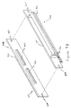
- FIG. 7A is a side view of an exemplary embodiment of the interconnection of a primary riser card and a secondary riser card.
- FIG. 7B is a first exploded perspective view of an exemplary embodiment of the interconnection of the primary and secondary riser cards shown in FIG. 7 A.
- FIG. 7C is a second exploded perspective view of an exemplary embodiment of the interconnection of the primary and secondary riser cards shown in FIG. 7 A.
- FIG. 8A illustrates a configuration of the primary riser card of FIG. 1 .
- FIG. 8B presents a set of trace lengths for the configuration shown in FIG. 8 A.
- FIG. 9A illustrates a configuration of the secondary riser card of FIG. 4 .
- FIG. 9B presents a set of trace lengths for the configuration shown in FIG. 9 A.
- FIG. 10A illustrates a configuration comprising a primary and secondary riser cards.
- FIG. 10B presents a set of trace lengths for the configuration shown in FIG. 10 A.
- FIG. 11A illustrates a configuration of a circuit board on which the riser cards of FIGS. 8A, 8 B, 9 A, 9 B, 10 A, and 10 B may be connected.
- FIG. 11B presents a set of trace lengths for the configuration shown in FIG. 11 A.
- FIG. 12 illustrates an exemplary embodiment of a circuit board onto which a primary and secondary riser cards may be coupled.
- FIG. 1 illustrates a front view of an exemplary embodiment of a primary riser card 100 .
- a “primary riser card” is defined as a riser card substrate 102 having a connecting edge 106 to couple to a socket or baseboard connector.
- the connecting edge 106 of the primary riser card 100 may be designed to couple to a PCI socket.
- the connecting edge 106 may comply with the PCI standard specification and may include one or more electrical contacts 110 to electrically couple the primary riser card 100 to a PCI bus.
- the distance between the connecting edge 106 and opposite edge 112 of the primary riser card is in the range of 0.25 inches to 1.75 inches. This is so that the primary riser card 100 will fit within the physical constraints of a 1U system.
- the primary riser card 100 is approximately one (1) inch high.
- the primary riser card 100 may include one or more sockets 104 which may be electrically coupled to one or more of the electrical contacts 110 .
- the term “socket”, as used throughout this document, is defined to be synonymous and interchangeable with the term “connector”.
- the one or more sockets 104 may be either 64-bit or 32-bit PCI sockets.
- the one or more sockets 104 may be mounted either on the front or back surface of the primary riser card substrate 102 so that it is substantially horizontal to the computer board on to which the primary riser card 100 may be coupled.
- FIG. 2 illustrates the back view of an exemplary embodiment of a primary riser card 200 .
- one or more interboard connectors 216 and 218 may be mounted on a surface of the primary card substrate 202 . These one or more interboard connectors 216 and 218 may also be mounted on the same surface or opposite surface as the socket 104 of the primary riser card 100 of FIG. 1 .
- the one or more interboard connectors 216 and 218 may be coupled to one or more electrical contacts 210 on a primary riser card 200 .
- the connectors may be electrically coupled to the one or more sockets 104 in FIG. 1 .
- These one or more connectors 216 and 218 may be capable of providing all signals of a PCI bus including the address lines, data lines, clock, and configuration lines.
- the one or more interboard connectors 216 and 218 may provide the signals for a 66 MHz PCI bus.
- the one or more interboard connectors 216 and 218 may include a second PCI socket.
- FIG. 3A illustrates a side view of the primary riser card 100 of FIG. 1 .
- the one or more sockets 104 are mounted on a first surface of the primary riser card substrate 102 in such a manner that when the primary riser card 100 is coupled to a baseboard connector on a computer board, the combined structure does not exceed 1.75 inches in height. This allows a first peripheral card to be coupled to the primary riser card's one or more sockets 104 .
- FIG. 3B illustrates a side view of an exemplary primary riser card 200 incorporating the one or more interboard connectors 216 and 218 (not shown) of FIG. 2 .
- These interboard connectors 216 and 218 may serve to couple a second peripheral card to the same PCI bus as a first peripheral card which may be coupled to the one or more sockets 204 on the primary riser card 200 .
- the connectors 216 and 218 may serve to couple to a secondary riser card.
- the one or more interboard connectors 216 and 218 may be a single 64-bit PCI socket.
- the one or more connectors 216 and 218 may be a set of two 90-pin connectors or three 60-pin connectors.
- FIG. 4 illustrates a front view of an exemplary embodiment of a secondary riser card 400 .
- a “secondary riser card” 400 is defined as a riser card substrate 402 having a socket 404 to couple to a peripheral card, and may be removably coupled to a primary riser card. Secondary riser cards are useful to allow two or more peripheral cards to electrically couple to a single socket on a computer board.
- the socket on the secondary riser card 400 is a 64-bit PCI socket.
- FIG. 5 illustrates the back view of one embodiment of a secondary riser card 500 .
- the secondary riser card 500 in addition to the socket 404 of FIG. 4, may include one or more connectors 506 and 510 for electrically coupling to a primary riser card.
- the one or more interboard connectors 506 and 510 may be mounted on the same or opposite surface as the socket 404 (in FIG. 4 ).
- FIG. 6 illustrates a side view of a secondary riser card 600 configuration.
- the secondary riser card substrate 602 has a PCI socket 604 mounted on a first surface and at least one interboard connector 606 mounted on a second surface.
- the width of the secondary riser card 600 is in the range of 0.25 inches to 1.75 inches so that the secondary riser card 600 will fit within the physical constraints of a 1U system.
- the secondary riser card may have a PCI socket and the one or more connectors mounted on the same surface of the substrate.
- FIG. 7A illustrates a side view of the interconnection of a primary riser card 702 and a secondary riser card 700 .
- This configuration comprises of a primary riser card 702 , including a substrate 710 , a socket 706 , and one or more interboard connectors 732 , coupled to a secondary riser card 700 , including a substrate 708 , a socket 704 , and one or more interboard connectors 730 .
- the riser cards being electrically coupled via the interboard connectors 730 and 732 .
- This side view also illustrates that in one embodiment the primary and secondary riser cards 702 and 700 may be of approximately the same height. According one configuration, these riser cards are less than 1.75 inches high.
- a connecting edge 712 on the primary riser card substrate 710 is provided to electrically couple the assembly 700 and 702 to a circuit board or computer board.
- the socket 704 on the secondary riser card 700 may be electrically coupled to the connecting edge 712 on the primary riser card 702 .
- the sockets 704 and 706 may be any combination of 32-bit and 64-bit PCI sockets. Such configuration would allow at least two peripheral cards to couple to a single PCI socket on a computer board while fitting within the physical constraints of a 1U system. In one configuration, the sockets 704 and 706 mounted on the primary and secondary riser cards are 64-bit PCI sockets.
- FIG. 7B illustrates a first exploded perspective view of one embodiment of the primary and secondary riser cards of FIG. 7 A.
- the primary riser card 702 which includes a substrate 710 , a socket 706 , and a connecting edge 712 , may be coupled to a secondary riser card 700 , which includes a substrate 708 , a socket 704 , and one or more interboard connectors 730 .
- FIG. 7C illustrates a second exploded perspective view of the embodiment shown in FIG. 7 A.
- the primary riser card 702 includes one or more interboard connectors 732 to couple to the interboard connectors 730 (in FIG. 7B) of the secondary riser card 700 .
- the primary and secondary riser cards 702 and 700 may also include one or more holes 720 and 722 through which a retaining mechanism or fastener may fit to secure the two cards 700 and 702 .
- FIG. 8A illustrates the signal transmission paths or traces for a PCI bus from a baseboard connector 802 or PCI socket on a computer board through a primary riser card and a peripheral card 806 coupled to the primary riser card.
- the signal path from the baseboard connector 802 to the PCI connector 804 on the primary riser card should be no longer than approximately 1.4 inches.
- the trace or signal path may be between approximately 0.3 to 1.1 inches in length.
- the trace length on the peripheral card or PCI card is defined by the PCI Specification, Revision 2.2 for 66 MHz buses.
- the trace on the peripheral card should be no longer than approximately 2 inches in length.
- FIG. 9A illustrates the signal transmission paths or traces for a PCI bus from a baseboard connector 902 or PCI socket on a computer board through a primary riser card, without a peripheral card coupled to it, to a secondary riser card with a peripheral device 908 coupled to it.
- the signal path from the baseboard connector 902 to the interboard connector 904 on the primary riser card may be no longer than approximately 2 inches and preferably between approximately 1 to 1.7 inches in length.
- the signal path from the interboard connector 910 on the secondary riser card to the PCI connector 906 on the secondary card may be no longer than approximately 1.9 inches and preferably between approximately 0.2 to 1.6 inches in length.
- the trace length on the peripheral card 908 or PCI card is defined by the PCI Specification, Revision 2.2 for 66 MHz buses and may be no longer than approximately 2 inches in length. These values are illustrated in FIG. 9 B.
- FIG. 10A illustrates the signal transmission paths or traces for a PCI bus from a baseboard connector 1002 or PCI socket on a computer board through both a primary riser card and a secondary riser card, each with a peripheral device 1012 and 1014 coupled to it.
- the PCI bus operates at 66 MHz.
- the PCI sockets on the primary and secondary riser cards are 64-bit PCI sockets.
- the signal path from the baseboard connector 1002 to the PCI socket 1004 on the primary riser card may be no longer than approximately 1.4 inches and preferably between approximately 0.3 to 1.1 inches in length.
- the signal path from the PCI socket 1004 to the interboard connector 1006 on the primary riser card may be no longer than approximately 1.5 inches and preferably between approximately 0.8 to 1.2 inches in length.
- the trace from the interboard connector 1010 on the secondary riser card to the PCI connector 1008 on the secondary card may be no longer than approximately 1.9 inches and preferably between approximately 0.2 to 1.6 inches in length.
- FIG. 11A illustrates a circuit board 1100 or computer board with a PCI bus and including a baseboard connector 1110 or PCI socket on which any of the primary and secondary riser card configurations shown in FIGS. 8A, 8 B, 9 A, 9 B, 10 A, and 10 B may be coupled.
- This circuit board and components thereon is only one of many systems on which a primary and secondary riser card may be coupled.
- the PCI bus identified as segments “C” and “D”, on the computer board 1100 is defined by the PCI Specification, Revision 2.2 and may include a host bridge 1102 and other PCI devices 1104 which comply with the PCI Specification, Revision 2.2. While a host bridge 1102 and a generic PCI device 1104 are shown in FIG. 11A, this is by way of illustration only and other devices may be employed. For instance, a Small Computer System Interface (SCSI) controller may be coupled to the PCI bus.
- SCSI Small Computer System Interface
- the trace or signal path between the host bridge 1102 and the PCI device 1104 should be a maximum of approximately 2 inches long.
- a “T” point 1106 defined by the intersection of segments “A”, “B”, and “C”, is selected on this segment such that the trace length from this point to either of the host bridge 1102 and PCI device 1104 is no than approximately 1.2 inches, and preferably no longer than approximately 1 inch, and the total length to the baseboard connector is no more than approximately 8.5 inches, and preferably no longer than 7 inches.
- the point at which the host bridge 1102 and PCI device 1104 couple to the PCI bus may be anywhere along segments “C” or “D”. That is, any of these devices may be coupled, alone or in combination, to the PCI bus anywhere along the bus without changing the character of the present invention. Additionally, PCI devices 1102 and 1104 need not couple at a “T” point 1106 as shown. In one embodiment, the host bridge 1102 may be coupled to segment “C” while the PCI device 1104 may be coupled to segment “D”.
- an attenuation resistor 1108 is placed between the “T” point 1106 and the baseboard connector 1110 .
- the function of the attenuation resistor 1108 is to attenuate reflection from the receivers on peripheral cards or PCI devices when the host-bridge 1102 is driving.
- the trace length from the attenuation resistor 1108 to the baseboard connector 1110 is no more than approximately 2.5 inches, and preferably no longer than approximately 2 inches.
- the trace length from the resistor 1108 to the “T” point 1106 should be no longer than approximately 6 inches, and preferably no longer than approximately 5 inches.
- the attenuation resistor 1108 may be less than or equal to approximately 200 Ohms.
- a pull-up resistor 1112 at the baseboard connector 1110 may be present to couple to a voltage source 1114 .
- the stub length from the pull-up resistor 1108 to the baseboard connector 1110 should be a maximum of approximately 1.2 inches, and preferably no longer than 1 inch.
- the pull-up resistor 1112 is less or equal to approximately 2K Ohms.
- FIG. 12 illustrates an exemplary configuration of how a primary riser card 1302 and a secondary riser card 1304 may be coupled to a circuit board 1306 .
- the secondary riser card 1304 is coupled to the primary riser card 1302 .
- the primary riser card 1302 may be coupled to a socket 1308 on the circuit board 1306 .
- each riser card 1302 and 1304 may include a socket 1310 and 1312 onto which a peripheral card may be coupled in a position substantially horizontal to the circuit board 1306 .
Landscapes
- Engineering & Computer Science (AREA)
- Theoretical Computer Science (AREA)
- Computer Hardware Design (AREA)
- General Engineering & Computer Science (AREA)
- General Physics & Mathematics (AREA)
- Physics & Mathematics (AREA)
- Human Computer Interaction (AREA)
- Power Engineering (AREA)
- Coupling Device And Connection With Printed Circuit (AREA)
- Bus Control (AREA)
- Traffic Control Systems (AREA)
- Exchange Systems With Centralized Control (AREA)
- Mobile Radio Communication Systems (AREA)
- Small-Scale Networks (AREA)
Priority Applications (11)
| Application Number | Priority Date | Filing Date | Title |
|---|---|---|---|
| US09/727,048 US6504725B1 (en) | 2000-11-29 | 2000-11-29 | Topology for PCI bus riser card system |
| TW090126755A TWI231414B (en) | 2000-11-29 | 2001-10-29 | Topology for 66 MHz PCI bus riser card system |
| BR0115684-5A BR0115684A (pt) | 2000-11-29 | 2001-11-06 | Topologia para sistema de cartão adaptador de barramento pci de 66 mhz |
| BRMU8103684-1U BR8103684Y1 (pt) | 2000-11-29 | 2001-11-06 | Dispositivo de cartão adaptador |
| AU2002216728A AU2002216728A1 (en) | 2000-11-29 | 2001-11-06 | Topology for 66 mhz pci bus riser card system |
| PCT/US2001/044108 WO2002044913A2 (en) | 2000-11-29 | 2001-11-06 | Topology for 66 mhz pci bus riser card system |
| HK03108432.6A HK1056624B (en) | 2000-11-29 | 2001-11-06 | Topology for 66 mhz pci bus riser card system |
| EP01998899A EP1340154B1 (de) | 2000-11-29 | 2001-11-06 | Topologie für 66 mhz pci bus erweiterungskarten system |
| CNB018197248A CN1262935C (zh) | 2000-11-29 | 2001-11-06 | 计算机、辅助竖板卡和计算机系统 |
| DE60110457T DE60110457T2 (de) | 2000-11-29 | 2001-11-06 | Topologie für 66 mhz pci bus erweiterungskarten system |
| AT01998899T ATE294416T1 (de) | 2000-11-29 | 2001-11-06 | Topologie für 66 mhz pci bus erweiterungskarten system |
Applications Claiming Priority (1)
| Application Number | Priority Date | Filing Date | Title |
|---|---|---|---|
| US09/727,048 US6504725B1 (en) | 2000-11-29 | 2000-11-29 | Topology for PCI bus riser card system |
Publications (1)
| Publication Number | Publication Date |
|---|---|
| US6504725B1 true US6504725B1 (en) | 2003-01-07 |
Family
ID=24921123
Family Applications (1)
| Application Number | Title | Priority Date | Filing Date |
|---|---|---|---|
| US09/727,048 Expired - Lifetime US6504725B1 (en) | 2000-11-29 | 2000-11-29 | Topology for PCI bus riser card system |
Country Status (9)
| Country | Link |
|---|---|
| US (1) | US6504725B1 (de) |
| EP (1) | EP1340154B1 (de) |
| CN (1) | CN1262935C (de) |
| AT (1) | ATE294416T1 (de) |
| AU (1) | AU2002216728A1 (de) |
| BR (2) | BR8103684Y1 (de) |
| DE (1) | DE60110457T2 (de) |
| TW (1) | TWI231414B (de) |
| WO (1) | WO2002044913A2 (de) |
Cited By (16)
| Publication number | Priority date | Publication date | Assignee | Title |
|---|---|---|---|---|
| US20030007339A1 (en) * | 2001-07-05 | 2003-01-09 | Harris Mark Roy | Stacked backplane assembly |
| US20040132348A1 (en) * | 2001-03-21 | 2004-07-08 | Yaakov Haggay | Patch panel |
| US20060007663A1 (en) * | 2004-07-09 | 2006-01-12 | Arvinmeritor Gmbh | Electronic control device for motor vehicles |
| WO2005114342A3 (de) * | 2004-05-21 | 2006-05-04 | Endress & Hauser Gmbh & Co Kg | Variables feldgerät für die automatisierungstechnik |
| US7075797B1 (en) * | 2005-06-14 | 2006-07-11 | Lenovo (Singapore) Pte Ltd. | Circuit board riser for volume sharing peripheral cards |
| US20060226711A1 (en) * | 2005-04-11 | 2006-10-12 | Eiring Chad D | Assembly identification by mounting configuration |
| US20060292901A1 (en) * | 2003-06-27 | 2006-12-28 | Emc Corporation | Invertible, pluggable module for variable I/O densities |
| US20080106862A1 (en) * | 2006-11-08 | 2008-05-08 | Super Micro Computer, Inc. | Server wherein an interior of which is connected with five expansion boards |
| US20090248943A1 (en) * | 2008-04-01 | 2009-10-01 | Inventec Corporation | Server |
| US20100328880A1 (en) * | 2009-06-29 | 2010-12-30 | Hon Hai Precision Industry Co., Ltd. | Computer system |
| US20110086520A1 (en) * | 2007-05-25 | 2011-04-14 | Dell Products, Lp | Interface Retention and Support Apparatus and Method of Use |
| US20110273853A1 (en) * | 2010-05-04 | 2011-11-10 | Hon Hai Precision Industry Co., Ltd. | Computer system with riser card |
| US20120246371A1 (en) * | 2011-03-23 | 2012-09-27 | Hon Hai Precision Industry Co., Ltd. | Test apparatus for pci card |
| US20120242362A1 (en) * | 2011-03-23 | 2012-09-27 | Hon Hai Precision Industry Co., Ltd. | Test apparatus |
| US20170133776A1 (en) * | 2015-11-10 | 2017-05-11 | Lenovo Enterprise Solutions (Singapore) Pte. Ltd. | Card stabilizer bracket |
| US11073873B1 (en) * | 2020-03-25 | 2021-07-27 | Intel Corporation | Electronic device interconnect |
Families Citing this family (4)
| Publication number | Priority date | Publication date | Assignee | Title |
|---|---|---|---|---|
| US10579574B2 (en) * | 2014-09-30 | 2020-03-03 | Keysight Technologies, Inc. | Instrumentation chassis with high speed bridge board |
| CN109085890B (zh) * | 2018-07-03 | 2020-07-07 | 无锡睿勤科技有限公司 | 一种扩展卡组件和服务器 |
| CN111273742B (zh) * | 2019-12-04 | 2022-04-12 | 深圳市时代通信技术有限公司 | 一种基于正交构架的高密度服务模块化系统 |
| US11735847B2 (en) * | 2020-08-19 | 2023-08-22 | Tyco Electronics (Shanghai) Co., Ltd. | Connector assembly |
Citations (6)
| Publication number | Priority date | Publication date | Assignee | Title |
|---|---|---|---|---|
| US4683550A (en) * | 1984-07-30 | 1987-07-28 | Burr-Brown Corporation | Personal computer instrumentation system including carrier board having bus-oriented plug-in instrumentation modules |
| US4885482A (en) * | 1988-07-13 | 1989-12-05 | Compaq Computer Corporation | Multiple computer interface circuit board |
| US5440755A (en) * | 1992-04-06 | 1995-08-08 | Accelerated Systems, Inc. | Computer system with a processor-direct universal bus connector and interchangeable bus translator |
| US5754796A (en) * | 1996-05-07 | 1998-05-19 | Wang; Daniel | Bus port transmission device |
| US6146150A (en) * | 1998-11-24 | 2000-11-14 | International Business Machines Corporation | Circuit card with separate interfaces for different bus architectures |
| US6241530B1 (en) * | 1997-12-17 | 2001-06-05 | Honeywell Inc. | Backplane assembly for printed circuit boards |
Family Cites Families (5)
| Publication number | Priority date | Publication date | Assignee | Title |
|---|---|---|---|---|
| US5121295A (en) * | 1991-02-13 | 1992-06-09 | Flytech Technology Company, Ltd. | Computer interface card mounting device |
| US5611057A (en) * | 1994-10-06 | 1997-03-11 | Dell Usa, L.P. | Computer system modular add-in daughter card for an adapter card which also functions as an independent add-in card |
| US5765008A (en) * | 1994-10-14 | 1998-06-09 | International Business Machines Corporation | Personal computer with riser card PCI and Micro Channel interface |
| US5734840A (en) * | 1995-08-18 | 1998-03-31 | International Business Machines Corporation | PCI and expansion bus riser card |
| US6046912A (en) * | 1999-06-03 | 2000-04-04 | Micron Electronics, Inc. | Computer system having riser board expansion capability |
-
2000
- 2000-11-29 US US09/727,048 patent/US6504725B1/en not_active Expired - Lifetime
-
2001
- 2001-10-29 TW TW090126755A patent/TWI231414B/zh not_active IP Right Cessation
- 2001-11-06 AT AT01998899T patent/ATE294416T1/de not_active IP Right Cessation
- 2001-11-06 CN CNB018197248A patent/CN1262935C/zh not_active Expired - Fee Related
- 2001-11-06 DE DE60110457T patent/DE60110457T2/de not_active Expired - Lifetime
- 2001-11-06 WO PCT/US2001/044108 patent/WO2002044913A2/en not_active Ceased
- 2001-11-06 BR BRMU8103684-1U patent/BR8103684Y1/pt not_active IP Right Cessation
- 2001-11-06 AU AU2002216728A patent/AU2002216728A1/en not_active Abandoned
- 2001-11-06 BR BR0115684-5A patent/BR0115684A/pt active IP Right Grant
- 2001-11-06 EP EP01998899A patent/EP1340154B1/de not_active Expired - Lifetime
Patent Citations (6)
| Publication number | Priority date | Publication date | Assignee | Title |
|---|---|---|---|---|
| US4683550A (en) * | 1984-07-30 | 1987-07-28 | Burr-Brown Corporation | Personal computer instrumentation system including carrier board having bus-oriented plug-in instrumentation modules |
| US4885482A (en) * | 1988-07-13 | 1989-12-05 | Compaq Computer Corporation | Multiple computer interface circuit board |
| US5440755A (en) * | 1992-04-06 | 1995-08-08 | Accelerated Systems, Inc. | Computer system with a processor-direct universal bus connector and interchangeable bus translator |
| US5754796A (en) * | 1996-05-07 | 1998-05-19 | Wang; Daniel | Bus port transmission device |
| US6241530B1 (en) * | 1997-12-17 | 2001-06-05 | Honeywell Inc. | Backplane assembly for printed circuit boards |
| US6146150A (en) * | 1998-11-24 | 2000-11-14 | International Business Machines Corporation | Circuit card with separate interfaces for different bus architectures |
Cited By (26)
| Publication number | Priority date | Publication date | Assignee | Title |
|---|---|---|---|---|
| US20040132348A1 (en) * | 2001-03-21 | 2004-07-08 | Yaakov Haggay | Patch panel |
| US7077710B2 (en) | 2001-03-21 | 2006-07-18 | Rit Technologies Ltd. | Patch panel |
| US6757177B2 (en) * | 2001-07-05 | 2004-06-29 | Tropic Networks Inc. | Stacked backplane assembly |
| US20030007339A1 (en) * | 2001-07-05 | 2003-01-09 | Harris Mark Roy | Stacked backplane assembly |
| US20060292901A1 (en) * | 2003-06-27 | 2006-12-28 | Emc Corporation | Invertible, pluggable module for variable I/O densities |
| WO2005114342A3 (de) * | 2004-05-21 | 2006-05-04 | Endress & Hauser Gmbh & Co Kg | Variables feldgerät für die automatisierungstechnik |
| US20080126659A1 (en) * | 2004-05-21 | 2008-05-29 | Endress + Hauser Gmbh + Co. Kg | Variable Field Device For Use In Automation Systems |
| US20060007663A1 (en) * | 2004-07-09 | 2006-01-12 | Arvinmeritor Gmbh | Electronic control device for motor vehicles |
| US20060226711A1 (en) * | 2005-04-11 | 2006-10-12 | Eiring Chad D | Assembly identification by mounting configuration |
| US8001681B2 (en) * | 2005-04-11 | 2011-08-23 | Liebert Corporation | Assembly identification by mounting configuration |
| US7075797B1 (en) * | 2005-06-14 | 2006-07-11 | Lenovo (Singapore) Pte Ltd. | Circuit board riser for volume sharing peripheral cards |
| US20080106862A1 (en) * | 2006-11-08 | 2008-05-08 | Super Micro Computer, Inc. | Server wherein an interior of which is connected with five expansion boards |
| US7499289B2 (en) * | 2006-11-08 | 2009-03-03 | Super Micro Computer, Inc. | Server wherein an interior of which is connected with five expansion boards |
| US8023275B2 (en) * | 2007-05-25 | 2011-09-20 | Dell Products, Lp | Interface retention and support apparatus and method of use |
| US20110086520A1 (en) * | 2007-05-25 | 2011-04-14 | Dell Products, Lp | Interface Retention and Support Apparatus and Method of Use |
| US20090248943A1 (en) * | 2008-04-01 | 2009-10-01 | Inventec Corporation | Server |
| US20100328880A1 (en) * | 2009-06-29 | 2010-12-30 | Hon Hai Precision Industry Co., Ltd. | Computer system |
| US8254130B2 (en) * | 2009-06-29 | 2012-08-28 | Hon Hai Precision Industry Co., Ltd. | Computer system |
| US20110273853A1 (en) * | 2010-05-04 | 2011-11-10 | Hon Hai Precision Industry Co., Ltd. | Computer system with riser card |
| US8369102B2 (en) * | 2010-05-04 | 2013-02-05 | Hon Hai Precision Industry Co., Ltd. | Computer system with riser card |
| US20120246371A1 (en) * | 2011-03-23 | 2012-09-27 | Hon Hai Precision Industry Co., Ltd. | Test apparatus for pci card |
| US20120242362A1 (en) * | 2011-03-23 | 2012-09-27 | Hon Hai Precision Industry Co., Ltd. | Test apparatus |
| US20170133776A1 (en) * | 2015-11-10 | 2017-05-11 | Lenovo Enterprise Solutions (Singapore) Pte. Ltd. | Card stabilizer bracket |
| US9979109B2 (en) * | 2015-11-10 | 2018-05-22 | Lenovo Enterprise Solutions (Singapore) Pte. Ltd. | Card stabilizer bracket |
| US11073873B1 (en) * | 2020-03-25 | 2021-07-27 | Intel Corporation | Electronic device interconnect |
| US12235691B2 (en) | 2020-03-25 | 2025-02-25 | Intel Corporation | Electronic device interconnect |
Also Published As
| Publication number | Publication date |
|---|---|
| AU2002216728A1 (en) | 2002-06-11 |
| DE60110457T2 (de) | 2006-04-27 |
| EP1340154B1 (de) | 2005-04-27 |
| CN1262935C (zh) | 2006-07-05 |
| EP1340154A2 (de) | 2003-09-03 |
| CN1505784A (zh) | 2004-06-16 |
| TWI231414B (en) | 2005-04-21 |
| BR8103684Y1 (pt) | 2015-03-10 |
| WO2002044913A3 (en) | 2003-01-16 |
| BR0115684A (pt) | 2004-08-10 |
| WO2002044913A2 (en) | 2002-06-06 |
| DE60110457D1 (de) | 2005-06-02 |
| ATE294416T1 (de) | 2005-05-15 |
| HK1056624A1 (en) | 2004-02-20 |
Similar Documents
| Publication | Publication Date | Title |
|---|---|---|
| US6504725B1 (en) | Topology for PCI bus riser card system | |
| US6731515B2 (en) | Riser assembly and method for coupling peripheral cards to a motherboard | |
| US6913471B2 (en) | Offset stackable pass-through signal connector | |
| US6363450B1 (en) | Memory riser card for a computer system | |
| US6629181B1 (en) | Incremental bus structure for modular electronic equipment | |
| US5781747A (en) | Method and apparatus for extending the signal path of a peripheral component interconnect bus to a remote location | |
| US10925167B2 (en) | Modular expansion card bus | |
| US7328290B2 (en) | System and method of automatically switching control of a bus in a processor-based device | |
| US8599564B2 (en) | Server architecture | |
| KR970701885A (ko) | 고대역폭 컴퓨터를 위한 모듈 구조(modular architecture for high bandwidth computers) | |
| US6527562B2 (en) | PCI expansion adapter with PC card slot and electronic apparatus provided with the same | |
| US9653830B1 (en) | Extending device for signal transmission and mainboard assembly | |
| US7272017B2 (en) | Method and apparatus for coupling a plurality of cards to an information handling system | |
| US6608761B2 (en) | Multiple processor cards accessing common peripherals via transparent and non-transparent bridges | |
| US6840808B2 (en) | Connector for a plurality of switching assemblies with compatible interfaces | |
| US20060063400A1 (en) | Connection structure for server blades | |
| US20060080484A1 (en) | System having a module adapted to be included in the system in place of a processor | |
| US6970054B2 (en) | Apparatus for terminating transmission lines to reduce electromagnetic interference in an electronic system | |
| US6288908B1 (en) | Peripheral apparatus for PC cards | |
| US7083423B1 (en) | Method and apparatus for mounting a card connector | |
| HK1056624B (en) | Topology for 66 mhz pci bus riser card system | |
| US20070016707A1 (en) | Configuration connector for information handling system circuit boards | |
| US6835894B2 (en) | Back plane structure for SCSI | |
| US20090019204A1 (en) | Self-healing noise dispersion system for high performance multidrop systems | |
| CN114968869B (zh) | 光口扩展卡 |
Legal Events
| Date | Code | Title | Description |
|---|---|---|---|
| AS | Assignment |
Owner name: INTEL CORPORATION, CALIFORNIA Free format text: ASSIGNMENT OF ASSIGNORS INTEREST;ASSIGNOR:LAM, DON T.;REEL/FRAME:011489/0442 Effective date: 20001130 |
|
| STCF | Information on status: patent grant |
Free format text: PATENTED CASE |
|
| FPAY | Fee payment |
Year of fee payment: 4 |
|
| FPAY | Fee payment |
Year of fee payment: 8 |
|
| FPAY | Fee payment |
Year of fee payment: 12 |