US6512805B1 - Light water reactor core and fuel assembly - Google Patents
Light water reactor core and fuel assembly Download PDFInfo
- Publication number
- US6512805B1 US6512805B1 US09/660,356 US66035600A US6512805B1 US 6512805 B1 US6512805 B1 US 6512805B1 US 66035600 A US66035600 A US 66035600A US 6512805 B1 US6512805 B1 US 6512805B1
- Authority
- US
- United States
- Prior art keywords
- fuel
- reactor core
- uranium
- plutonium
- fuel assembly
- Prior art date
- Legal status (The legal status is an assumption and is not a legal conclusion. Google has not performed a legal analysis and makes no representation as to the accuracy of the status listed.)
- Expired - Lifetime
Links
- 239000000446 fuel Substances 0.000 title claims abstract description 470
- XLYOFNOQVPJJNP-UHFFFAOYSA-N water Substances O XLYOFNOQVPJJNP-UHFFFAOYSA-N 0.000 title claims abstract description 105
- 229910052778 Plutonium Inorganic materials 0.000 claims abstract description 151
- OYEHPCDNVJXUIW-UHFFFAOYSA-N plutonium atom Chemical compound [Pu] OYEHPCDNVJXUIW-UHFFFAOYSA-N 0.000 claims abstract description 151
- JFALSRSLKYAFGM-UHFFFAOYSA-N uranium(0) Chemical compound [U] JFALSRSLKYAFGM-UHFFFAOYSA-N 0.000 claims abstract description 148
- 230000000712 assembly Effects 0.000 claims abstract description 98
- 238000000429 assembly Methods 0.000 claims abstract description 98
- 229910052770 Uranium Inorganic materials 0.000 claims abstract description 95
- 238000004033 diameter control Methods 0.000 claims abstract description 88
- 239000011800 void material Substances 0.000 claims abstract description 65
- 238000009395 breeding Methods 0.000 claims abstract description 50
- 230000001488 breeding effect Effects 0.000 claims abstract description 50
- 229910052768 actinide Inorganic materials 0.000 claims abstract description 28
- 150000001255 actinides Chemical class 0.000 claims abstract description 28
- 238000010521 absorption reaction Methods 0.000 claims abstract description 25
- 230000007246 mechanism Effects 0.000 claims description 19
- 239000000126 substance Substances 0.000 claims description 17
- 230000002093 peripheral effect Effects 0.000 claims description 15
- 238000009835 boiling Methods 0.000 abstract description 16
- 239000002826 coolant Substances 0.000 abstract description 13
- 230000004048 modification Effects 0.000 abstract description 3
- 238000012986 modification Methods 0.000 abstract description 3
- 230000000694 effects Effects 0.000 description 63
- 238000009826 distribution Methods 0.000 description 44
- 230000003247 decreasing effect Effects 0.000 description 18
- 230000007774 longterm Effects 0.000 description 18
- 239000000463 material Substances 0.000 description 14
- OKTJSMMVPCPJKN-UHFFFAOYSA-N Carbon Chemical compound [C] OKTJSMMVPCPJKN-UHFFFAOYSA-N 0.000 description 10
- 229910052799 carbon Inorganic materials 0.000 description 10
- 238000010276 construction Methods 0.000 description 10
- 239000010935 stainless steel Substances 0.000 description 10
- 229910001220 stainless steel Inorganic materials 0.000 description 10
- 230000009471 action Effects 0.000 description 8
- 238000006243 chemical reaction Methods 0.000 description 8
- 238000004519 manufacturing process Methods 0.000 description 8
- 238000010248 power generation Methods 0.000 description 8
- 230000009257 reactivity Effects 0.000 description 6
- 238000000034 method Methods 0.000 description 5
- 230000001603 reducing effect Effects 0.000 description 5
- 239000003054 catalyst Substances 0.000 description 4
- 238000005260 corrosion Methods 0.000 description 4
- 230000007797 corrosion Effects 0.000 description 4
- 230000002542 deteriorative effect Effects 0.000 description 4
- 230000004992 fission Effects 0.000 description 4
- 230000002285 radioactive effect Effects 0.000 description 4
- 239000000941 radioactive substance Substances 0.000 description 4
- 230000001052 transient effect Effects 0.000 description 4
- 230000008859 change Effects 0.000 description 3
- 230000006872 improvement Effects 0.000 description 3
- 239000002901 radioactive waste Substances 0.000 description 3
- 238000012958 reprocessing Methods 0.000 description 3
- 238000004904 shortening Methods 0.000 description 3
- XLYOFNOQVPJJNP-ZSJDYOACSA-N Heavy water Chemical compound [2H]O[2H] XLYOFNOQVPJJNP-ZSJDYOACSA-N 0.000 description 2
- 230000002159 abnormal effect Effects 0.000 description 2
- 238000005452 bending Methods 0.000 description 2
- 230000000052 comparative effect Effects 0.000 description 2
- 238000001816 cooling Methods 0.000 description 2
- 238000004821 distillation Methods 0.000 description 2
- 238000005516 engineering process Methods 0.000 description 2
- 238000001704 evaporation Methods 0.000 description 2
- 230000035755 proliferation Effects 0.000 description 2
- 230000005855 radiation Effects 0.000 description 2
- JFALSRSLKYAFGM-OIOBTWANSA-N uranium-235 Chemical compound [235U] JFALSRSLKYAFGM-OIOBTWANSA-N 0.000 description 2
- OYEHPCDNVJXUIW-FTXFMUIASA-N 239Pu Chemical compound [239Pu] OYEHPCDNVJXUIW-FTXFMUIASA-N 0.000 description 1
- 102000052567 Anaphase-Promoting Complex-Cyclosome Apc1 Subunit Human genes 0.000 description 1
- 101000890325 Homo sapiens Anaphase-promoting complex subunit 1 Proteins 0.000 description 1
- UFHFLCQGNIYNRP-UHFFFAOYSA-N Hydrogen Chemical compound [H][H] UFHFLCQGNIYNRP-UHFFFAOYSA-N 0.000 description 1
- OYEHPCDNVJXUIW-AHCXROLUSA-N Plutonium-240 Chemical compound [240Pu] OYEHPCDNVJXUIW-AHCXROLUSA-N 0.000 description 1
- 229910001093 Zr alloy Inorganic materials 0.000 description 1
- 229910052790 beryllium Inorganic materials 0.000 description 1
- ATBAMAFKBVZNFJ-UHFFFAOYSA-N beryllium atom Chemical compound [Be] ATBAMAFKBVZNFJ-UHFFFAOYSA-N 0.000 description 1
- 238000013461 design Methods 0.000 description 1
- 238000011156 evaluation Methods 0.000 description 1
- 230000008020 evaporation Effects 0.000 description 1
- 238000000605 extraction Methods 0.000 description 1
- 230000004907 flux Effects 0.000 description 1
- 229910052739 hydrogen Inorganic materials 0.000 description 1
- 239000001257 hydrogen Substances 0.000 description 1
- 238000003780 insertion Methods 0.000 description 1
- 230000037431 insertion Effects 0.000 description 1
- 238000005025 nuclear technology Methods 0.000 description 1
- 238000003860 storage Methods 0.000 description 1
- 230000005514 two-phase flow Effects 0.000 description 1
Images




Classifications
-
- G—PHYSICS
- G21—NUCLEAR PHYSICS; NUCLEAR ENGINEERING
- G21C—NUCLEAR REACTORS
- G21C3/00—Reactor fuel elements and their assemblies; Selection of substances for use as reactor fuel elements
- G21C3/30—Assemblies of a number of fuel elements in the form of a rigid unit
- G21C3/32—Bundles of parallel pin-, rod-, or tube-shaped fuel elements
-
- G—PHYSICS
- G21—NUCLEAR PHYSICS; NUCLEAR ENGINEERING
- G21C—NUCLEAR REACTORS
- G21C1/00—Reactor types
- G21C1/04—Thermal reactors ; Epithermal reactors
- G21C1/06—Heterogeneous reactors, i.e. in which fuel and moderator are separated
- G21C1/08—Heterogeneous reactors, i.e. in which fuel and moderator are separated moderator being highly pressurised, e.g. boiling water reactor, integral super-heat reactor, pressurised water reactor
-
- G—PHYSICS
- G21—NUCLEAR PHYSICS; NUCLEAR ENGINEERING
- G21C—NUCLEAR REACTORS
- G21C3/00—Reactor fuel elements and their assemblies; Selection of substances for use as reactor fuel elements
- G21C3/30—Assemblies of a number of fuel elements in the form of a rigid unit
- G21C3/32—Bundles of parallel pin-, rod-, or tube-shaped fuel elements
- G21C3/326—Bundles of parallel pin-, rod-, or tube-shaped fuel elements comprising fuel elements of different composition; comprising, in addition to the fuel elements, other pin-, rod-, or tube-shaped elements, e.g. control rods, grid support rods, fertile rods, poison rods or dummy rods
-
- G—PHYSICS
- G21—NUCLEAR PHYSICS; NUCLEAR ENGINEERING
- G21C—NUCLEAR REACTORS
- G21C5/00—Moderator or core structure; Selection of materials for use as moderator
- G21C5/02—Details
-
- G—PHYSICS
- G21—NUCLEAR PHYSICS; NUCLEAR ENGINEERING
- G21C—NUCLEAR REACTORS
- G21C7/00—Control of nuclear reaction
- G21C7/06—Control of nuclear reaction by application of neutron-absorbing material, i.e. material with absorption cross-section very much in excess of reflection cross-section
- G21C7/08—Control of nuclear reaction by application of neutron-absorbing material, i.e. material with absorption cross-section very much in excess of reflection cross-section by displacement of solid control elements, e.g. control rods
- G21C7/10—Construction of control elements
- G21C7/117—Clusters of control rods; Spider construction
-
- Y—GENERAL TAGGING OF NEW TECHNOLOGICAL DEVELOPMENTS; GENERAL TAGGING OF CROSS-SECTIONAL TECHNOLOGIES SPANNING OVER SEVERAL SECTIONS OF THE IPC; TECHNICAL SUBJECTS COVERED BY FORMER USPC CROSS-REFERENCE ART COLLECTIONS [XRACs] AND DIGESTS
- Y02—TECHNOLOGIES OR APPLICATIONS FOR MITIGATION OR ADAPTATION AGAINST CLIMATE CHANGE
- Y02E—REDUCTION OF GREENHOUSE GAS [GHG] EMISSIONS, RELATED TO ENERGY GENERATION, TRANSMISSION OR DISTRIBUTION
- Y02E30/00—Energy generation of nuclear origin
- Y02E30/30—Nuclear fission reactors
Definitions
- the present invention relates to a light water reactor core and fuel assemblies composing a reactor core and, more particularly, to a light water reactor core wherein in a boiling water reactor (BWR), the BWR has the same levels in cost efficiency and degree of safety as those of an existing BWR under operation now, that is, the BWR is oriented to plutonium (Pu) multi-recycle having a breeding ratio near 1.0 or slightly larger and having a negative void coefficient with minimizing modification of the reactor core structure of the existing BWR under operation now, and to fuel assemblies used for the boiling water reactor.
- BWR boiling water reactor
- fissionable materials such as uranium-235 and plutonium-239 are being consumed by fission reaction
- fertile materials such as uranium-238 and plutonium-240 are being converted to fissionable materials.
- the ratio of an amount of fissionable materials contained in the fuel unloaded from the reactor core to an amount of fissionable materials contained in the fuel loaded from the reactor core is called as a breeding ratio.
- the breeding ratio in a conventional light water reactor is approximately 0.5. Methods of improving the breeding are studied in order to effectively use the uranium resources.
- Japanese Patent Application Laid-Open No.55-10591 and Nuclear Technology, Vol.59, pages 212-227 (1982) propose a method that the breeding ratio is improved in a pressurized water reactor by densely arranging fuel assemblies in a triangular lattice to decrease the water-to-fuel volume ratio.
- the obtained breeding ratio is 0.9 at maximum, and accordingly the fissionable material needs to be supplied in order to continue operation without reducing the output power.
- it can be considered to further decrease the water-to-fuel ratio by narrowing the gap between the fuel rods.
- it is difficult to narrow the gap between the fuel rods because there are limitations in manufacturing the fuel assembly and in securing thermal margin.
- Japanese Patent Application Laid-Open No.1-227993 proposes a method that the water-to-fuel ratio is effectively decreased by making use of steam void generated in the reactor core which characterizes a boiling water reactor. It is shown that this conventional technology can increase the plutonium multiplication ratio (the ratio of amount of fissionable plutonium contained in fuel unloaded from the reactor core to an amount of fissionable plutonium contained in fuel loaded in the reactor core, that is, the breeding ratio to fissionable plutonium) up to nearly 1, but it is not shown that the breeding ratio (which is smaller by 4 to 5% than the plutonium multiplication ratio in the case where natural uranium is enriched by adding plutonium) can be increased approximately 1 or larger.
- the plutonium multiplication ratio the ratio of amount of fissionable plutonium contained in fuel unloaded from the reactor core to an amount of fissionable plutonium contained in fuel loaded in the reactor core, that is, the breeding ratio to fissionable pluton
- the words that the breeding ratio is larger than near 1 in the present invention means that the breeding ratio is larger than 0.98.
- Japanese Patent Application Laid-Open No.8-21890 discloses that in a reactor core comprising fuel which is enriched by adding plutonium or plutonium and an actinide to a uranium containing at least one of a depleted uranium, natural uranium, a degraded uranium and a low enriched uranium, the reactor core has a breeding ratio of near 1.0 or larger than 1.0 and a negative void coefficient.
- the prior art is not a technology which is intended to further improve the ability of a control rod to be manufactured and the cost performance of the control rod.
- An object of the present invention is to provide a reactor core which has the same levels in power generation cost, thermal margin and degree of safety as those of a light water reactor under operation now and fuel assemblies used for the reactor core.
- the present invention provide a light water reactor core comprising fuel which is enriched by adding plutonium or plutonium and an actinide (hereinafter, referred to as plutonium and the like) to a uranium containing at least one of a depleted uranium, natural uranium, a degraded uranium and a low enriched uranium (hereinafter, referred to as depleted uranium and the like), which further comprises fuel assemblies having fuel rods arranged in a triangular lattice configuration; and large-diameter control rods to be inserted into the fuel assemblies, the large-diameter control rod comprising at least one absorption rod having a transverse cross-sectional area larger than a cross-sectional area of a unit lattice cell of the fuel rod, wherein a breeding ratio of the reactor core is near 1.0 or larger than 1.0, and a void coefficient of the reactor core is negative
- the present invention in order to contribute to long-term stable energy supply, it is possible to realize the breeding ratio of 1.0 using the fuel enriched by adding plutonium to depleted uranium (hereinafter, referred to as the first effect). According to the present invention, since it is possible to attain the breeding ratio near 1.0 or larger than 1.0 using the fuel enriched by adding plutonium to depleted uranium, the depleted uranium and the like can be burned as if the plutonium would be used as a catalyst, which can contribute to the long-term stable energy supply.
- a first preferable embodiment is a fuel assembly comprising fuel which is enriched by adding plutonium and the like to depleted uranium and the like, wherein a breeding ratio of the fuel assembly is near 1.0 or larger than 1.0.
- the first effect can be attained. Since it is possible to attain the breeding ratio near 1.0 or larger than 1.0 using the fuel enriched by adding plutonium to depleted uranium, the depleted uranium and the like can be burned as if the plutonium would be used as a catalyst, which can contribute to the long-term stable energy supply.
- a second preferable embodiment is a light water reactor core comprising fuel assemblies having fuel rods arranged in a triangular lattice configuration; and large-diameter control rods to be inserted into the fuel assemblies, the large-diameter control rod comprising at least one absorption rod having a transverse cross-sectional area larger than a cross-sectional area of a unit lattice cell of the fuel rod.
- the first effect can be attained, and at the same time, in order to contribute to the long-term stable energy supply, it is possible to realize the breeding ratio of 1.0 by reducing the water-to-fuel ratio and by using the fuel enriched by adding plutonium to depleted uranium (hereinafter, referred to as the second effect).
- the second effect by using the large-diameter control rod, the mechanical strength of the control rod can be increased and accordingly bending and buckling of the control rod can be suppressed when the control rod is inserted or withdrawn.
- number of absorption rods per fuel assembly can be reduced, and accordingly the control rod can be easily manufactured to reduce the manufacturing cost.
- a third preferable embodiment is a light water reactor core comprising a water-excluding region on a surface of the guide tube, the water-excluding region being formed of a substance having a slowing down power smaller than a slowing down power of light water. According to the third embodiment, the second effect can be attained.
- a fourth preferable embodiment is a fuel assembly which comprises fuel rods closely arranged in a triangular lattice configuration, a gap between the rods being within the range of 0.7 to 2.0 mm.
- the light water reactor core may be constructed using the fuel assemblies. According to the fourth embodiment, the second effect can be attained.
- a fifth preferable embodiment is a fuel assembly of which an effective water-to-fuel volume ratio is within the range of 0.1 to 0.6.
- the light water reactor core may be constructed using the fuel assemblies.
- the second effect can be attained.
- by combination of the fuel assembly of closely-compact lattice having the fuel formed by adding plutonium to depleted uranium and the like and the large-diameter control rod to make the effective water-to-fuel volume ratio within the range of 0.1 to 0.6 it is possible to attain the breeding ratio near 1.0 or larger than 1.0 and to contribute to the long-term stable energy supply.
- a sixth preferable embodiment is a light water reactor core wherein an average fissionable plutonium enrichment in the reactor core except for an outer peripheral portion and blanket portions of a top and a bottom end portions is within the range of 6 to 20 wt %. According to the sixth embodiment, the second effect can be attained.
- a seventh preferable embodiment is a fuel assembly wherein an average fissionable plutonium enrichment in the fuel assembly except for blanket portions of a top and a bottom end portions is within the range of 6 to 20 wt %. According to the seventh embodiment, the second effect can be attained.
- an eighth preferable embodiment is a light water reactor core wherein a core-average void fraction under operation of an output power higher than 50% of a rated output power is within the range of 45 to 70%.
- the second effect can be attained.
- the eighth embodiment by combination of the fuel assembly of closely-compact lattice and the coolant of a high void fraction, the ratio of neutrons in resonance energy range is increased, the Doppler effect is increased and the absolute value of negative void coefficient is decreased. Therefore, the degree of safety under events of a power increase event, a pressurizing event and a coolant void fraction decreasing event can be improved.
- a ninth preferable embodiment is a light water reactor core wherein all the large-diameter control rods connected to one control drive mechanism are inserted into one fuel assembly, and the large-diameter control rods are inserted into all of the fuel assemblies loaded in a region except for an outermost peripheral of the reactor core. According to the ninth embodiment, the second effect can be attained without deteriorating the reactor shut down margin.
- a tenth preferable embodiment is a light water reactor core wherein all the large-diameter control rods connected to one control drive mechanism are inserted into one hexagonal or square fuel assembly, and the large-diameter control rods are inserted into all of the fuel assemblies loaded in a region except for an outermost peripheral of the reactor core. According to the tenth embodiment, the second effect can be attained without deteriorating the reactor shut down margin.
- an eleventh preferable embodiment is a light water reactor core wherein the plurality of large-diameter control rods connected to one control drive mechanism are inserted into three hexagonal fuel assemblies, and the large-diameter control rods are inserted into all of the fuel assemblies loaded in a region except for an outermost peripheral of the reactor core. According to the eleventh embodiment, the second effect can be attained without deteriorating the reactor shut down margin.
- a twelfth preferable embodiment is a light water reactor core wherein the plurality of large-diameter control rods connected to one control drive mechanism are inserted into four square fuel assemblies, and the large-diameter control rods are inserted into all of the fuel assemblies loaded in a region except for an outermost peripheral of the reactor core. According to the twelfth embodiment, the second effect can be attained without deteriorating the reactor shut down margin.
- a thirteenth preferable embodiment is a light water reactor core wherein the large-diameter control rod comprises a follower portion in a top end portion, the follower portion being made of a substance such as carbon, heavy water, beryllium, a zirconium alloy, a stainless steel or the like having a slowing down power smaller than a slowing down power of light water.
- the second effect can be attained.
- a fourteenth preferable embodiment is a fuel assembly wherein an average value of fissionable plutonium enrichments of a fuel rod arranged in a region adjacent to the guide tube and a fuel rod arranged in a region most distant from the center of the fuel assembly is smaller than an average value of fissionable plutonium enrichments of fuel rods arranged in the other positions.
- the second effect can be attained.
- the power peaking in the fuel assembly is reduced and accordingly the thermal margin can be increased.
- a fifteenth preferable embodiment is a light water reactor core wherein an average output power density of in a reactor core region except for an outer peripheral portion and blanket portions of a top and a bottom end portions is within the range of 100 kW/l to 300 kW/l.
- the required plutonium inventory per unit output power can be reduced to operate as many nuclear power plants as possible using a determined amount of plutonium in order to contribute the long-term stable energy supply (hereinafter, referred to as a third effect), and the output power and the burn-up in the same level as those of an existing light water reactor plant under operation can be attained with the same thermal margin using the same materials and the same sized pressure vessel as those of the existing light water reactor plant in order to make the electric power generation cost compatible with that of the existing light water reactor (hereinafter, referred to as a fourth effect), and further the negative void coefficient can be realized by increasing of neutron leakage in the reactor core height direction and by using swing of power distribution in the reactor core height direction at increasing output power in order to make the degree of safety compatible with that of the existing light water reactor (hereinafter, referred to as a fifth effect).
- the plutonium inventory per unit output power is reduced by increasing the power density of the reactor core to 100 to 300 kW/l, and the capacity of the present invention electric power plant operable by a determined amount of plutonium can be increased, which contributes to the long-term stable energy supply.
- a sixteenth preferable embodiment is a light water reactor core wherein in regard to a height direction of the reactor core except for blanket portions of a top and a bottom end portions, a length having an average fissionable plutonium enrichment with respect to a horizontal cross section of the fuel assembly-higher than 6 wt % is within the range of 40 cm to 140 cm. According to the sixteenth embodiment, the third effect, the fourth effect and the fifth effect can be attained.
- the plutonium inventory can be decreased by generating the same output power as an ABWR (Advanced Boiling Water Reactor) under construction at present time can be obtained using a pressure vessel having a diameter compatible with that of the ABWR, and by employing the short-length fuel assemblies for the reactor core height of 40 to 140 cm. Therefore, many of the reactors according to the present invention can be operated using the plutonium produced from used fuel of light water reactors under the limited deposits of natural uranium in the world, which can contribute the long-term stable energy supply.
- ABWR Advanced Boiling Water Reactor
- the reactor core having the negative void coefficient can be realized by increasing of neutron leakage in the reactor core height direction and by using swing of power distribution in the reactor core height direction, and accordingly the reactor core can attain the degree of safety in the same level as that of the existing light water reactor of a fuel burned-only type. That is, in regard to a height direction of the reactor core except for blanket portions of a top and a bottom end portions, a length having an average fissionable plutonium enrichment with respect to a horizontal cross section of the fuel assembly higher than 6 wt % is within the range of 40 cm to 140 cm.
- the plutonium inventory per unit output power is reduced, and the capacity of the present invention electric power plant operable by a determined amount of plutonium can be increased, which contributes to the long-term stable energy supply.
- the negative void coefficient can be increased by increasing of neutron leakage in the reactor core height direction at increasing the output power, which contributes the safety.
- a seventeenth preferable embodiment is a fuel assembly wherein in regard to a height direction of the reactor core except for blanket portions of a top and a bottom end portions, a length having an average fissionable plutonium enrichment with respect to a horizontal cross section of the fuel assembly higher than 6 wt % is within the range of 40 cm to 140 cm.
- the third effect, the fourth effect and the fifth effect can be attained.
- the plutonium inventory can be decreased by generating the same output power as the ABWR under construction at present time can be obtained using a pressure vessel having a diameter compatible with that of the ABWR, and by employing the short-length fuel assemblies for the reactor core height of 40 to 140 cm. Therefore, many of the reactors according to the present invention can be operated using the plutonium produced from used fuel of light water reactors under the limited deposits of natural uranium in the world, which can contribute the long-term stable energy supply.
- the reactor core having the negative void coefficient can be realized by using the short length fuel assemblies to increase the neutron leakage in the reactor core height direction and to use the swing of power distribution in the reactor core height direction, and accordingly the reactor core can attain the degree of safety in the same level as that of the existing light water reactor of a burned-only fuel type. That is, in regard to a height direction of the reactor core except for blanket portions of a top and a bottom end portions, a length having an average fissionable plutonium enrichment with respect to a horizontal cross section of the fuel assembly higher than 6 wt % is within the range of 40 cm to 140 cm.
- the plutonium inventory per unit output power is reduced, and the capacity of the present invention electric power plant operable by a determined amount of plutonium can be increased, which contributes to the long-term stable energy supply.
- the negative void coefficient can be increased by increasing of neutron leakage in the reactor core height direction at increasing the output power, which contributes the safety.
- an eighteenth preferable embodiment is a light water reactor core wherein the reactor core except for the outermost periphery of the reactor core is radially divided into two equal-area regions, and fuel assemblies are loaded so that an average value of number of cycles staying in the reactor core of the fuel assemblies loaded in the outer reactor core region is smaller than an average value of number of cycles staying in the reactor core of the fuel assemblies loaded in the inner reactor core region.
- the fourth effect can be attained.
- the electric power generation cost can be made compatible with that of the existing BWR by employing the diameter of the pressure vessel, the operating conditions such as the output power and the used materials nearly equal to those of the BWR under operation even though the performance is largely improved.
- a nineteenth preferable embodiment is a light water reactor core wherein an average value of orifice pressure drop coefficient of the fuel assemblies in an outermost periphery of the reactor core and adjacent to the outermost periphery is larger than an average value of orifice pressure drop coefficient of the fuel assemblies in the other regions.
- the fourth effect can be attained.
- the electric power generation cost can be made compatible with that of the existing BWR by employing the diameter of the pressure vessel, the operating conditions such as the output power and the used materials nearly equal to those of the BWR under operation even though the performance is largely improved.
- a twentieth preferable embodiment is a fuel assembly wherein an average value of fissionable plutonium enrichment in an upper half of the fuel assembly except for blanket portions of a top and a bottom end portions is lower than an average value of fissionable plutonium enrichment in an lower half.
- the fifth effect can be attained.
- the reactor core having the negative void coefficient can be realized- by using the upper-and-lower two-region fuel assemblies to increase the neutron leakage in the upper and lower directions of the reactor core and to use the swing of power distribution in the upper and the lower directions of the reactor core, and accordingly the reactor core can attain the degree of safety in the same level as that of the existing light water reactor of a burned-only fuel type.
- the output power distribution in the reactor core height direction is flattened to increase the thermal margin and the swing of the output power distribution in the reactor core height direction acts at increasing the amount of steam generation to increase the negative void reactivity coefficient, which contributes to improvement of the degree of safety.
- a twenty-first preferable embodiment is a fuel assembly wherein in regard to a height direction of the fuel assembly except for blanket portions of a top and a bottom end portions, the fuel assembly comprises regions having an average fissionable plutonium enrichment higher than 6 wt % in an upper and a lower parts of the fuel assembly; and a region having an average fissionable plutonium enrichment lower than 6 wt % in a region near a middle portion between the upper and the lower regions.
- the fifth effect can be attained.
- the reactor core having the negative void coefficient can be realized by using the axially heterogeneous fuel assemblies to increase the neutron leakage in the upper and lower directions of the reactor core and to use the swing of power distribution in the upper and the lower directions of the reactor core, and accordingly the reactor core can attain the degree of safety in the same level as that of the existing light water reactor of a burned-only fuel type.
- the fuel assembly comprises the regions having the average fissionable plutonium enrichment higher than 6 wt % in the upper and the lower parts of the fuel assembly and the region having the average fissionable plutonium enrichment lower than 6 wt % in the region near the middle portion between the upper and the lower regions, the negative void reactivity coefficient due to the output power distribution swing in the vertical direction of the reactor core when the output power of the reactor core is increased and the amount of steam generation is increased, which contributes to improvement of the safety.
- the plutonium inventory capable of being loaded in the reactor core is increased by the neutron absorption effect of the region near the middle position in the axial direction of the reactor core, which improves the function as a plutonium storage reactor.
- the height of the reactor core is relatively becomes higher and the total length of the assembly becomes longer, the thermal margin to the maximum linear power density becomes larger.
- a twenty-second preferable embodiment is a light water reactor core wherein a steam weight ratio at the reactor core exit under operation of an output power higher than 50% of the rated output power is within the range of 20 wt % to 40 wt %.
- the twenty-second embodiment in order to the degree of safety of the light water reactor is made comparative with the existing light water reactor, the distillation function by boiling is maintained and the radioactive substances existing in the reactor core can be enclosed inside the pressure vessel (hereinafter referred to as a sixth effect).
- the radioactive substances such as corrosion products accumulated in the reactor core can be enclosed in the reactor core by maintaining the distillation function because the steam weight ratio of the coolant at the reactor core exit is suppressed below 40 wt %. Therefore, the radiation level in the turbine side can be maintained in the same level in the existing BWR plant under operation now, and at the same time the radiation level can be extremely reduced compared to one of the conventional conceptual breeder reactors of a steam cooling fast breeder reactor.
- a twenty-third preferable embodiment is a fuel assembly wherein plutonium and uranium extracted from used fuel are loaded at a time.
- a light water reactor core may be composed of the fuel assemblies.
- the plutonium and the uranium in order to cope with the nuclear non-proliferation, the plutonium and the uranium can be recycled together by abolishing sole extraction of the plutonium (hereinafter, referred to as a seventh effect).
- the plutonium and the uranium are recycled together, the effect of nuclear non-proliferation can be improved.
- a twenty-fourth preferable embodiment is a fuel assembly wherein plutonium, uranium and actinides extracted from used fuel are loaded at a time.
- a light water reactor core may be composed of the fuel assemblies.
- the actinides can be recycled by placing the actinides in the reactor core together with the uranium and the plutonium (hereinafter, referred to as an eighth effect).
- the amount of increased actinides can be made zero by balancing the generating amount and the eliminating amount, and the long half life actinides, one of the most problem nuclides among the radioactive wastes, can be enclosed only in the nuclear reactor, the reprocessing facility and the fuel manufacturing facility. Therefore, the protection to the environment can be improved.
- An amount of natural uranium resource over the world is estimated to be around 15 million tons which corresponds to the amount capable of operation one thousand existing light water reactor plants of electric power 1000 MW for about 100 years.
- depleted uranium of slightly less than 15 million tons and fissionable plutonium of 15 thousands tons are left. Therefore, using the fuel which is the depleted uranium enriched by the plutonium, a power reactor having 1.0 breeding ratio (RBWR: Resource-Renewable Boiling Water Reactor) can continue nuclear fission of the depleted uranium using the plutonium like a catalyst with 10 ton fissionable plutonium inventory, including in- and out-core, per 1000 MW electric power output.
- RBWR Resource-Renewable Boiling Water Reactor
- the effective water-to-fuel volume ratio (Vm/Vf)eff is a value obtained by modifying a geometrical water-to-fuel volume ratio (Vm/Vf)geo (a water-to-fuel volume ratio without generation of steam void) in taking generation of steam void into consideration.
- Vm/Vf geometrical water-to-fuel volume ratio
- the ratio F relates to a core-average steam void fraction V (%) as follows.
- f is a ratio of a density of saturation steam to a density of saturation water.
- ratio F is generally as a small value as approximately 1/20, the ratio F can be approximated as follows.
- FIG. 2 shows the relationship among the effective water-to-fuel volume ratio, the conversion ratio defined from neutron balance and three factors composing the conversion ratio.
- ⁇ ratio of useless neutron capture (including neutron leakage) to neutron absorption by fissionable substance.
- the existing light water reactor under operation now has an effective water-to-fuel volume ratio of approximately 2.0 and a breading ratio of approximately 0.5.
- the breeding ratio near 1 can be attained with a conversion ratio above 0.85 by increasing the fissionable plutonium enrichment within a range to be described later and by increasing neutron leakage to the blanket.
- the effective water-to-fuel volume ratio for satisfying the above is below 0.6.
- the core-average steam void fraction needs to be a value exceeding 70% in order to make the effective water-to-fuel volume ratio below 0.1, the two-phase flow condition at the reactor core exit can not be kept at a transient event.
- the effective water-to-fuel volume ratio of 0.1 to 0.6 can be attained by closely arranging the fuel rods, or by making use of the steam void produced in the reactor core, or by excluding the moderator by inserting a follower in an inserting position of the control rod when the control rod is not placed in the inserting position, or by combining the above three methods.
- FIG. 3 shows an example of relationship between gap between rods and geometrical water-to-fuel volume ratio.
- FIG. 3 shows the cases where the diameters of the fuel rod are within the range of approximately 9.5 to 12.3 mm which are used in the existing light water reactors and the fuel rod lattice is regular triangular.
- the (Vm/Vf)geo of the fuel rod lattice becomes below approximately 0.9.
- the (Vm/Vf)geo of the fuel assembly system becomes a value larger than the (Vm/Vf)geo of the fuel rod lattice by 0.1 to 0.2 when the gap region between the fuel assemblies and the control rod insertion region are taking into consideration. Therefore, in order to realize the effective water-to-fuel volume ratio below 0.6 under the condition of the geometrical water-to-fuel volume ratio, it can be understood from Equation 1 that the core-average steam void fraction needs to be above 45% (it can be understood from the relationship shown in FIG.
- the ratio (Vm/Vf)geo can be made smaller than approximately 0.6 with the steam void fraction of 0%.
- FIG. 4 shows the relationship between fissile PU enrichment and breeding ratio.
- the breeding ratio is decreased as the fissionable plutonium enrichment is increased, it has been found that the breeding ratio of near 1 can be attained up to the fissionable plutonium enrichment of 20 wt % by increasing neutron leakage to the blanket in making use of increase of the excessive reactivity, as described above.
- a method considered is that a large-diameter control rod composed of an absorption rod having a cross-sectional area larger than a cross-sectional area of the fuel rod unit lattice cell is inserted into the fuel assembly.
- the local power peaking coefficient of the fuel rod can be decreased by nearly 30% or more (by employing the enrichment distribution, if necessary). Further, due to small change in burn-up and small change in void reactivity and together with the other means to be described below, the local power peaking coefficient of the fuel rod can be decreased by nearly 40% or more. Therefore, the height of the fuel assembly (effective core length) having an average linear power density equal to or more than that of the existing boiling water type light water reactor becomes 40 cm or more, that is, nearly 1/10 times as small as that of the existing boiling water type light water reactor.
- the void coefficient reducing effect can be used.
- the effective core length is smaller than 140 cm, the negative void coefficient can be realized by combining the other means to be described below.
- a ratio of power generation in the blanket portion is increased due to the shortening of the effective core length, the average power density in the region other than the blanket portion becomes approximately 100 to 300 kW/l due to the shortening of the effective core length.
- the electric power generation cost can be kept in the same level as that of the existing light water reactor and the degree of safety can be also kept in the same level as that of the existing light water reactor.
- the plutonium inventory can be reduced, and accordingly many power generating plants can be operated by a definite amount of plutonium, which realizes the stable energy supply.
- the above-mentioned fifth effect is produced by the following action.
- the power distribution in the axial direction of the reactor core can be flattened and as a result the plutonium inventory can be reduced.
- the steam void fraction in the reactor core is increased.
- the power distribution is swung to the lower portion of the reactor core where the fissionable plutonium enrichment is relatively lower and the neutron importance is small, and thereby the reactivity of the reactor core can be decreased (the negative void coefficient).
- the reactor core structure of closely arranging the fuel rods in the regular triangle lattice configuration can be realized by inserting the large-diameter control rod into the fuel assembly.
- possible reactor core construction are that all the large-diameter control rods connected to one control rod drive mechanism are inserted into one hexagonal fuel assembly, and the large-diameter control rods are inserted into all the hexagonal fuel assemblies loaded in a region except for the outermost periphery of the reactor core, and that a plurality of large-diameter control rods connected to one control rod drive mechanism are inserted into three hexagonal fuel assemblies, and the large-diameter control rods are inserted into all the hexagonal fuel assemblies loaded in a region except for the outermost periphery of the reactor core.
- Both of the reactor core structures can secure the reactor shut-down margin, and the former can reduce number of assemblies loaded to the reactor core by making the fuel assembly large in size, and the latter can reduce number of the control rod drive mechanisms. Further, according to the studies of the inventors of the present invention, in a case of combination of the square fuel assembly and the large-diameter control rod, the reactor core structure of closely arranging the fuel rods in a regular triangular lattice configuration can be realized.
- the fissionable plutonium enrichment of the fuel rods in the fuel assembly in the combination of the fuel assembly having the hexagonal or square transversal cross section and the large-diameter control rod, power peaking occurs in the fuel rod adjacent to the guide tube or the fuel rod in a region most distant from the center of the fuel assembly. Therefore, the power distribution in the assembly can be flattened by making the fissionable plutonium enrichment of the fuel rods in these regions smaller than the fissionable plutonium enrichment of the fuel rods in the other regions.
- the above-mentioned fourth effect is produced by the following action.
- the reactor core except for the outermost periphery of the reactor core is radially divided into two equal-area regions, and fuel assemblies are loaded so that an average value of number of cycles staying in the reactor core of the fuel assemblies loaded in the outer core region is smaller than an average value of number of cycles staying in the reactor core of the fuel assemblies loaded in the inner core region.
- the neutron infinite multiplication factor in the outer region of the reactor core can be made higher than that in the inner region, and accordingly the power distribution in the radial direction of the reactor core can be flattened.
- the required fissionable plutonium enrichment can be reduced.
- the effect of neutron leakage out of the reactor core peripheral portion is particularly large on the fuel assemblies in the outermost layer of the reactor core and adjacent to the outermost layer, and as a result the output power of the fuel assemblies in these region becomes lower compared to that of the assemblies in the other regions and consequently the coolant flow rate of the fuel assemblies in these region is increased. Therefore, the flow distribution can be flattened by that the average value of orifice pressure drop coefficient of the fuel assemblies in an outermost periphery of the reactor core and adjacent to the outermost periphery is set so as to be larger than the average value of orifice pressure drop coefficient of the fuel assemblies in the other regions.
- the coolant flow rate near the outermost periphery of the reactor core can be reduced, and accordingly the total coolant flow rate can be reduced.
- the steam void fraction can be increased in the region having the large orifice pressure drop coefficient, which can contribute to improvement of the void coefficient and increase of the breeding ratio.
- the above-mentioned sixth effect is produced by the following action.
- the breeding ratio can be made larger than 1.0 by employing light water steam cooling, there are problems in that it is necessary to develop a material having a high-temperature resistance and strength higher than that of the material used in the existing BWR and in that radioactive nuclides such as corrosion products flow out of the reactor core together with the steam.
- the coolant is maintained in a saturation temperature two-phase state and at the saturation temperature even when the output power is increased by an abnormal transient event. Therefore, the same structural material as in the existing light water reactor can be used, and the reactor core having a breeding ratio above 1.0 can be realized while the radioactive nuclides such as corrosion products is prevented from being contained in the steam flowing to the turbine.
- the above-mentioned first and seventh effects are produced by the following action.
- description will be made on the fuel which is enriched by adding plutonium to depleted uranium produced as the residue at manufacturing enriched uranium used for the existing light water reactors.
- plutonium to depleted uranium produced as the residue at manufacturing enriched uranium used for the existing light water reactors.
- the fuel which is enriched by adding plutonium to natural uranium or the degraded uranium or low enriched uranium (0.71 wt % to 2.0 wt %) instead of the depleted uranium, it is possible to realize a reactor core having performance in regard to the breeding ratio and the void coefficient prior to the reactor core using the fuel which is enriched by adding plutonium to the depleted uranium by lowering the fissionable plutonium enrichment by approximately 0.5 wt % or more compared to the case of using the fuel which is enriched by adding plutonium to the depleted uranium.
- the above-mentioned eighth effect is produced by the following action.
- the long-life radioactive nuclides are brought in an equilibrium state in the reactor core and the amount of the long-life radioactive nuclides becomes constant. Therefore, in the reactor core in accordance with the present invention, the amount of increased actinides can be made zero by balancing the generating amount and the eliminating amount. Therefore, it is possible to realize a nuclear reactor system which is capable of enclosing the long half life actinides, one of the most problem nuclides among the radioactive wastes, only in the nuclear reactor, the reprocessing facility and the fuel manufacturing facility.
- FIG. 1 is a cross-sectional plan view showing a first embodiment of a reactor core in accordance with the present invention.
- FIG. 2 is a graph showing the relationship between fuel rod lattice constant necessary for expressing a conversion ratio and effective water-to-fuel volume ratio.
- FIG. 3 is a graph showing the relationship between gap between rods and geometrical water-to-fuel volume ratio.
- FIG. 4 is a graph showing the relationship between fissile PU enrichment and breeding ratio.
- FIG. 5 is a graph explaining change in an output power distribution when a steam void fraction is increased.
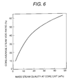
- FIG. 6 is a graph showing the relationship between core-averaged seam void fraction and mass steam quality at a reactor core exit.
- FIG. 7 is a cross-sectional plan view showing a fuel assembly to be loaded to the reactor core.
- FIG. 8 is a view showing an arrangement of fuel assemblies in the embodiment of the reactor core shown FIG. 1 under the equilibrium core state.
- FIG. 9 is a view showing an orifice distribution in the embodiment of FIG. 1 .
- FIG. 10 is a view showing the distribution of enrichment in the axial direction of a fuel assembly to be loaded to the reactor core of FIG. 1 .
- FIG. 11 is a view showing the distribution of enrichment of fuel rods in the fuel assembly to be loaded to the reactor core of FIG. 1 .
- FIG. 12 is a graph showing the distributions of output power and void fraction in the axial direction of the reactor core in the embodiment of FIG. 1 .
- FIG. 13 is a view showing the distribution of enrichment in the axial direction of a fuel assembly to be loaded to a second embodiment of a reactor core in accordance with the present invention.
- FIG. 14 is a cross-sectional plan view showing a third embodiment of a reactor core in accordance with the present invention.
- FIG. 15 is a cross-sectional plan view showing a fuel assembly to be loaded to the reactor core of FIG. 14 .
- FIG. 16 is a view showing an arrangement of fuel assemblies in the embodiment of the reactor core shown FIG. 14 under the equilibrium core state.
- FIG. 17 is a view showing an orifice distribution in the embodiment of FIG. 14 .
- FIG. 18 is a cross-sectional plan view showing a fuel assembly to be loaded to a fourth embodiment of a reactor core in accordance with the present invention.
- FIG. 19 is a cross-sectional plan view showing a fuel assembly to be loaded to a fifth embodiment of a reactor core in accordance with the present invention.
- FIG. 20 is a cross-sectional plan view showing a fuel assembly to be loaded to a sixth embodiment of a reactor core in accordance with the present invention.
- FIG. 21 is a cross-sectional plan view showing a seventh embodiment of a reactor core in accordance with the present invention.
- FIG. 22 is a cross-sectional plan view showing a fuel assembly to be loaded to the reactor core of FIG. 21 .
- FIG. 23 is a view showing an arrangement of fuel assemblies in the embodiment of the reactor core shown FIG. 21 under the equilibrium core state.
- FIG. 24 is a view showing an orifice distribution in the embodiment of FIG. 21 .
- FIG. 25 is a view showing the distribution of enrichment in the axial direction of a fuel assembly to be loaded to the reactor core of FIG. 21 .
- FIG. 26 is a cross-sectional plan view showing a fuel assembly to be loaded to an eighth embodiment of a reactor core in accordance with the present invention.
- FIG. 27 is a cross-sectional plan view showing a fuel assembly to be loaded to a ninth embodiment of a reactor core in accordance with the present invention.
- FIG. 28 is a horizontal sectional view of a fuel assembly loaded in a reactor core of a tenth embodiment of the present invention.
- the reactor cores of electric power of 1350 MW class are described in the following embodiments, the output power capacity is not limited to 1350 MW. It should be recognized that the present invention may be applied to the reactor cores having the other output power capacity by changing number of the fuel assemblies.
- FIG. 1 is a cross-sectional plan view showing the first embodiment of a reactor core having an electric output power of 1356 MWe.
- FIG. 1 shows 504 fuel assemblies 1 ; and 157 control rod drive mechanisms 2 each of which operates three large-diameter control rods to be inserted into three fuel assemblies, respectively.
- FIG. 7 shows the cross section of the fuel assembly lattice.
- fuel rods 4 of 10.1 mm diameter are arranged in a regular triangular configuration with a 1.3 mm gap between the rods to form an equilateral hexagonal assembly having 12 fuel rod rows.
- a guide tube 6 to insert the large-diameter control rod 5 thereinto is disposed in the region having an area equivalent to 3 fuel rod layers, that is, an area equivalent to 19 fuel rod unit lattice cells.
- the large-diameter control rod is formed of an absorption rod of a stainless steel tube filled with B 4 C. Further, the large-diameter control rod has a follower portion in the top end portion, the follower portion being made of carbon which is a substance having a slowing-down power smaller than that of light water.
- FIG. 8 shows an arrangement of fuel assemblies under the equilibrium core state.
- Each of the numerals written in each of the fuel assemblies 1 indicates a period staying in the reactor core by cycle numbers.
- the 5 cycle fuels staying in the reactor core for the longest period are loaded in the outermost periphery of the reactor core where the neutron importance is low.
- the fuels of 1 cycle staying period in the reactor core having the highest neutron infinite multiplication factor are loaded in the outer region of the reactor core in the inner side of the outermost periphery to flatten the power distribution in the radial direction of the reactor core.
- the fuels of 2 to 4 cycle staying periods in the reactor core are distributively loaded to flatten the power distribution in the radial direction of the reactor core.
- FIG. 10 shows the axial distribution of fissionable plutonium enrichment averaged over the horizontal cross section of the fuel assembly for the equilibrium reactor core.
- the uranium to be added with plutonium is the depleted uranium.
- the height of the reactor core is 70 cm, and the reactor core is divided three regions at the levels of 20 cm and 49 cm from the bottom end of the reactor core, and the fissionable plutonium enrichments are 19 wt %, 0 wt % and 19 wt %, respectively, and the average fissionable plutonium enrichment is 11.1 wt %.
- FIG. 11 is a horizontal cross-sectional view showing the 19 wt % fissionable plutonium enrichment region of the fuel assembly.
- the fissionable plutonium enrichments are three kinds of 19.1 wt %, 18.5 wt % and 17.5 wt %, and the average enrichment is 19 wt %.
- FIG. 12 shows the distributions of core-average output power and core-average void fraction in the axial direction of the reactor core.
- the core-average void fraction is 60%
- the mass steam quality at reactor core exit is 32 Wt %.
- the output power of the present reactor core is 1350 MWe which is equal to that of the existing ABWR, and the circumscribed radius of the reactor core is 2.9 m which is nearly equal to that of the ABWR.
- the height of the reactor core is 70 cm, and the blankets having heights of 20 cm and 25 cm are attached to the top and the bottom of the reactor core to form a short-length fuel assembly.
- the total length of the fuel rod is nearly equal to that of ABWR fuel and the MCPR is 1.31 which sufficiently satisfies the thermal design standard value of 1.24.
- the plutonium inventory converted to the amount of fissionable plutonium per 1000 MWe output power is as small as 6.0 tons though the fuel rods are closely packed. Even including the period of plutonium staying outside the reactor core such as fuel reprocessing, the plutonium inventory is less than 10 tons per 1000 MWe.
- the portions having the fissionable plutonium enrichment of 19 wt % in the upper and the lower positions there are the portions having the fissionable plutonium enrichment of 19 wt % in the upper and the lower positions, and the middle portion between them is formed of depleted uranium not containing the fissionable plutonium.
- the steam void fraction in the reactor core is increased.
- the power distribution in the upper portion of the reactor core is swung to the middle region of the reactor core where the fissionable plutonium enrichment is not contained. Thereby, the negative void coefficient is inserted.
- the mass steam quality at the reactor core exit is 32 wt %, and accordingly all the coolant does not become vapor and the coolant can be maintained in a two-phase state even when an abnormal transient event occurs. Therefore, similar to the existing BWR, the radioactive substances accumulated in the reactor core such as corrosion products are enclosed in the reactor core by evaporation operation of boiling and prevented from being transported to the turbine side.
- the BWR of the present embodiment is capable of cope with the long-term stable energy supply under the degree of safety comparative with that of the fuel burning-only light water reactor under operation now and using the pressure vessel having a size nearly equal to that of the ABWR under construction now.
- the BWR of the present embodiment outputs the amount of power equal to that of the ABWR, and can attain burn-up of 65 GWd/t.
- a void coefficient of the existing BWR under operation now (a value at present) is ⁇ 7.0 ⁇ 10 ⁇ 4 ⁇ k/k/% void.
- the value for the present embodiment is designed to be ⁇ 0.5 ⁇ 10 ⁇ 4 ⁇ k/k/% void of which the absolute value is smaller than the value at present.
- the thermal margin to an event of increasing pressure or to an event of decreasing coolant temperature is relatively large. From the above reason, the BWR reactor core of the present embodiment has safety margins for various kinds of transient events which are larger than those of the existing BWR under operation now.
- the large-diameter control rod having an outer diameter larger than that of the fuel rod is employed as the absorption rod.
- the mechanical strength of the control rod can be increased and accordingly bending and buckling of the control rod can be suppressed when the control rod is inserted or withdrawn.
- number of absorption rods per fuel assembly can be reduced, and accordingly the control rod can be easily manufactured to reduce the manufacturing cost.
- the breeding ratio of 1.01 can be realized by the fuel enriched by adding the fissile PU of average 11.1 wt % to the depleted uranium, and 1500 units of 1000 MWe reactors can be operated for 10 thousands years using the uranium reserves of 15 million tons in the world, and accordingly the long-term stable energy supply can be established. Further, since the diameter of the pressure vessel, the operating conditions such as output power and the used materials are the same as those of the existing BWR under operation, the electric power generation cost can be suppressed to the same level as that of the existing BWR even though the performance is largely progressed.
- the safety margin can be secured in the same level as that of the existing BWR by maintaining the evaporating function by boiling to enclose the radioactive substances in the pressure vessel.
- the same or more effects can be obtained by the fuel enriched by adding plutonium to natural uranium or the degraded uranium recovered from used fuel or the low enriched uranium instead of the depleted uranium.
- the fissile PU enrichment can be reduced by 0.5 wt % or more compared to the case of using the depleted uranium due to increase in an amount of uranium-235 contained in the fuel.
- the breeding ratio to the fissile PU can be increased by nearly 3% or more, and the void coefficient can be made negative.
- the Pu inventory can be reduced, number of the RBWRs capable of being operated can be further increased.
- the power coefficient including the Doppler coefficient can be made negative even if the void coefficient is 0 or slightly positive. According to the study of the inventors of the present invention, it has been shown from an evaluation result on the safety that the negative or positive void coefficient is essentially no problem if the power coefficient is negative. Therefore, the thermal margin can be increased by increasing the length of the reactor core portion. Further, the breeding ratio can be increased by narrowing the gap between the fuel rods.
- the other actinides can be added together with Pu.
- the RBWR is high in the average energy of neutrons
- plutonium is hardly converted to actinides having higher mass numbers and at the same time the actinides can be eliminated by nuclear fission reaction.
- the depleted uranium region is arranged in the position slightly higher than the middle position of the reactor core in the present embodiment, but it is not limited to that position.
- the values of axial power peaking can be made equal by combining the fissile PU enrichments in the upper and the lower portions and the position of the depleted uranium region.
- the present embodiment is a reactor core of an electric power output of 1356 MWe, and has further shortened fuel assemblies.
- the horizontal cross section and the cross section of the fuel assembly lattice of the present embodiment are the same as FIG. 1 and FIG. 7 of Embodiment 1, respectively.
- FIG. 13 shows the axial distribution of fissionable plutonium enrichment averaged over the horizontal cross section of the fuel assembly for the equilibrium reactor core.
- the uranium to be added with plutonium is the depleted uranium.
- the height of the reactor core is 45 cm, and the reactor core is divided two regions at the levels of 8/12 from the bottom end of the reactor core, and the fissionable plutonium enrichment in the upper region is 13 wt % and the fissionable plutonium enrichment in the upper region is 12 wt %. Further, depleted uranium blankets having heights of 25 cm and 20 cm are attached to the top and the bottom of the reactor core portion, respectively.
- the construction of the fuel assembly is the same as that of Embodiment 1.
- the regular triangular lattice closed-compact hexagonal fuel assembly having a gap between rods of 1.3 mm By the combination of the regular triangular lattice closed-compact hexagonal fuel assembly having a gap between rods of 1.3 mm, the core-average void fraction of 60% and the large-diameter control rod, an effective water-to-fuel volume ratio of 0.27 was attained, and a breeding ratio of 1.01 was realized.
- the present embodiment does not have the depleted uranium region not containing the fissile PU, and the reactor core portion is as short as 45 cm.
- the fuel assembly is an upper-and-lower two region fuel having different fissile PU enrichments at the levels of 15 cm from the top end of the reactor core, and the fissionable plutonium enrichment in the upper region is 13 wt % and the fissionable plutonium enrichment in the upper region is 12 wt %.
- the RBWR of the present embodiment outputs the amount of power equal to that of the ABWR, and can attain burn-up of 45 GWd/t using the pressure vessel having a size nearly equal to that of the ABWR under construction now.
- the same or more effects can be also obtained by the fuel enriched by adding plutonium to natural uranium or the degraded uranium recovered from used fuel or the low enriched uranium instead of the depleted uranium.
- the other actinides can be added together with Pu.
- FIG. 14 is a reactor core in which the electric output power is the same as that of Embodiment 1, and number of fuel assemblies and the structure of the fuel assembly are changed from Embodiment 1.
- FIG. 14 is a cross-sectional plan view showing the present embodiment of a reactor core having an electric output power of 1356 MWe.
- FIG. 14 shows 609 fuel assemblies 7 ; and 193 control rod drive mechanisms 8 each of which operates large-diameter control rods to be inserted into three fuel assemblies.
- FIG. 15 shows the cross section of the fuel assembly lattice.
- fuel rods 4 of 10.1 mm diameter are arranged in a regular triangular configuration with a 1.3 mm gap between the rods to form an equilateral hexagonal assembly having 11 fuel rod rows.
- two guide tubes 11 to insert the large-diameter control rods 10 thereinto are disposed in the regions having an area equivalent to 2 fuel rod rows, that is, an area equivalent to 7 fuel rod unit lattice cells.
- the large-diameter control rod is formed of an absorption rod of a stainless steel tube filled with B 4 C. Further, the large-diameter control rod has a follower portion in the top end portion, the follower portion being made of carbon which is a substance having a slowing-down power smaller than that of light water.
- FIG. 16 shows an arrangement of fuel assemblies under the equilibrium core state.
- Each of the numerals written in each of the fuel assemblies 7 indicates a period staying in the reactor core by cycle numbers.
- the 5 cycle fuels staying in the reactor core for the longest period are loaded in the outermost periphery of the reactor core where the neutron importance is low.
- the fuels of 1 cycle staying period in the reactor core having the highest neutron infinite multiplication factor are loaded in the outer region of the reactor core in the inner side of the outermost periphery to flatten the power distribution in the radial direction of the reactor core.
- the fuels of 2 to 4 cycle staying periods in the reactor core are distributively loaded to flatten the power distribution in the radial direction of the reactor core.
- FIG. 17 shows an orifice distribution in the equilibrium reactor core state, and the numeral written in the fuels indicates difference in opening degree of an orifice placed in the fuel supporting portion, and there are two regions for the orifice opening degree.
- the orifice diameter in the reactor outermost peripheral region (number 1 ) where the fuel assembly power is small is smaller than the orifice diameter in the inner region.
- the axial distribution of the fissile PU enrichment averaged with the horizontal cross section of the fuel assembly is the same as that of FIG. 10 of Embodiment 1.
- the area of the region occupied by the control rod in the present embodiment is decreased from one region of 19 fuel rod unit lattice cells to two regions of 7 fuel rod unit lattice cells, but the control rod value is nearly equal to that of Embodiment 1 because the absorption rods are distributively inserted into the fuel assembly.
- number of fuel rods loaded in the reactor core is increased compared to Embodiment 1, and accordingly the average linear power density is reduced to improve the thermal margin.
- an effective water-to-fuel volume ratio of 0.28 is also attained.
- the reactor core characteristics are the same as those of Embodiment 1 and the same effect can be obtained.
- the same or more effects can be also obtained by the fuel enriched by adding plutonium to natural uranium or the degraded uranium recovered from used fuel or the low enriched uranium instead of the depleted uranium.
- the other actinides can be added together with Pu.
- the present embodiment is a reactor core of which the reactor core performance is improved on the base of the structure of Embodiment 1.
- the present embodiment is of 1356 MWe electric output power, and the reactor core cross section is the same as that of FIG. 1 of Embodiment 1.
- FIG. 18 shows the cross section of the fuel assembly lattice.
- fuel rods 4 of 10.1 mm diameter are arranged in a regular triangular configuration with a 1.3 mm gap between the rods to form an equilateral hexagonal assembly having 12 fuel rod rows.
- a guide tube 6 to insert the large-diameter control rod 5 thereinto is disposed in the region having an area equivalent to 3 fuel rod rows, that is, an area equivalent to 19 fuel rod unit lattice cells.
- the large-diameter control rod is formed of an absorption rod of a stainless steel tube filled with B 4 C. Further, the large-diameter control rod has a follower portion in the top end portion, the follower portion being made of carbon which is a substance having a slowing-down power smaller than that of light water. All of the configuration of fuel assemblies in the reactor core, the orifice state and the axial distribution of fissionable plutonium enrichment averaged over the horizontal cross section of the fuel assembly for the equilibrium reactor core are the same as FIG. 8, FIG. 9 and FIG. 10 of Embodiment 1, respectively.
- Embodiment 1 comparing with Embodiment 1 the effective water-to-fuel volume ratio can be improved and the power peaking in the fuel assembly can be suppressed by excluding the moderator around the guide tube.
- the reactor core characteristics are the same as those of Embodiment 1 and the same effect can be obtained.
- the same or more effects can be also obtained by the fuel enriched by adding plutonium to natural uranium or the degraded uranium recovered from used fuel or the low enriched uranium instead of the depleted uranium.
- the other actinides can be added together with Pu.
- the present embodiment is a reactor core of which the reactor core performance is improved on the base of the structure of Embodiment 1.
- the present embodiment is of 1356 MWe electric output power, and the reactor core cross section is the same as that of FIG. 1 of Embodiment 1.
- FIG. 19 shows the cross section of the fuel assembly lattice.
- fuel rods 4 of 10.1 mm diameter are arranged in a regular triangular configuration with a 1.3 mm gap between the rods to form an equilateral hexagonal assembly having 12 fuel rod rows.
- the large-diameter control rod is formed of an absorption rod of a stainless steel tube filled with B 4 C. Further, the large-diameter control rod has a follower portion in the top end portion, the follower portion being made of carbon which is a substance having a slowing-down power smaller than that of light water.
- the area of the region occupied by the control rod in the present embodiment is decreased from one region of 19 fuel rod unit lattice cells of Embodiment 1 to three regions of 7 fuel rod unit lattice cells.
- the absorption rods can be distributively inserted into the fuel assembly, and consequently the control rod value is improved compared to Embodiment 1.
- the other reactor core characteristics are the same as those of Embodiment 1 and the same effect can be obtained.
- the same or more effects can be also obtained by the fuel enriched by adding plutonium to natural uranium or the degraded uranium recovered from used fuel or the low enriched uranium instead of the depleted uranium.
- the other actinides can be added together with Pu.
- FIG. 20 shows the construction of the present embodiment of the fuel assembly.
- fuel rods 14 of 10.8 mm diameter are closely arranged in a regular triangular configuration with a 1.3 mm minimum gap between the rods.
- a guide tube 16 to insert the large-diameter control rod 15 thereinto is disposed in the region having an area equivalent to 2 fuel rod rows, that is, an area equivalent to 7 fuel rod unit lattice cells.
- the large-diameter control rod is formed of an absorption rod of a stainless steel tube filled with B 4 C, and the large-diameter control rod has a follower portion in the top end portion, the follower portion being made of carbon which is a substance having a slowing-down power smaller than that of light water.
- the large-diameter control rods to be inserted into four of the fuel assemblies are operated by one control rod driving mechanism.
- the fissile PU enrichment of fuel rods facing the channel box and fuel rods facing the guide tube is made lower than that of the other fuel rods.
- the same or more effects can be also obtained by the fuel enriched by adding plutonium to natural uranium or the degraded uranium recovered from used fuel or the low enriched uranium instead of the depleted uranium.
- the other actinides can be added together with Pu.
- FIG. 21 is a reactor core in which the electric output power is the same as that of Embodiment 1, and the number of fuel assemblies, the structure of the fuel assembly and the control rod drive mechanism are changed from Embodiment 1.
- FIG. 21 is a cross-sectional plan view showing the present embodiment of a reactor core having an electric output power of 1356 MWe.
- FIG. 21 shows 313 fuel assemblies 18 ; and 313 control rod drive mechanisms 18 each of which operates a large-diameter control rod to be inserted into one fuel assembly.
- FIG. 22 shows the cross section of the fuel assembly lattice.
- fuel rods 4 of 10.1 mm diameter are arranged in a regular triangular configuration with a 1.3 mm gap between the rods to form an equilateral hexagonal assembly having 15 fuel rod rows.
- a guide tube 21 to insert the large-diameter control rod 20 thereinto is disposed in the region having an area equivalent to 4 fuel rod rows, that is, an area equivalent to 37 fuel rod unit lattice cells.
- the large-diameter control rod is formed of an absorption rod of a stainless steel tube filled with B 4 C. Further, the large-diameter control rod has a follower portion in the top end portion, the follower portion being made of carbon which is a substance having a slowing-down power smaller than that of light water.
- FIG. 23 shows an arrangement of fuel assemblies under the equilibrium core state.
- Each of the numerals written in each of the fuel assemblies 17 indicates a period staying in the reactor core by cycle numbers.
- the 5 cycle fuels staying in the reactor core for the longest period are loaded in the outermost periphery of the reactor core where the neutron importance is low.
- the fuels of 1 cycle staying period in the reactor core having the highest neutron infinite multiplication factor are loaded in the outer region of the reactor core in the inner side of the outermost periphery to flatten the power distribution in the radial direction of the reactor core.
- the fuels of 2 to 4 cycle staying periods in the reactor core are distributively loaded in the inner region of the reactor core, and one 5 cycle fuel staying in the reactor core is loaded at the center of the reactor core. By doing so, the power distribution in the inner region is flattened.
- FIG. 24 shows an orifice distribution in the equilibrium reactor core state.
- the numeral written in the fuels indicates difference in opening degree of an orifice placed in the fuel supporting portion.
- the orifice diameter in the reactor outermost peripheral region (number 5 ) where the fuel assembly output power is small is smaller than the orifice diameters in the inner region.
- FIG. 25 shows the axial distribution of the fissile PU enrichment averaged with the horizontal cross section of the fuel assembly.
- the uranium to be added with Pu is depleted uranium.
- number of fuel assemblies to be loaded in the reactor core is reduced from 504 assemblies of Embodiment 1 to 313 assemblies by increasing number of fuel rods per one fuel assembly to make the fuel assembly large in size, and thereby the reactor core is made small in size.
- the control rod value is made nearly equivalent to that of Embodiment 1.
- One unit of the control rod drive mechanism is used for each of the control rods to be inserted into the fuel assembly.
- the reactor core is constructed so that the large-diameter control rod is also inserted into the fuel assembly loaded in the outermost periphery of the reactor core.
- a reactor core may be designed so that the control rod is not inserted into the fuel assembly in the outermost periphery which has a small effect on securing reactor shut-down margin.
- the same or more effects can be also obtained by the fuel enriched by adding plutonium to natural uranium or the degraded uranium recovered from used fuel or the low enriched uranium instead of the depleted uranium.
- the other actinides can be added together with Pu.
- the present embodiment is a reactor core in which the electric output power is the same as that of Embodiment 1, and number of fuel assemblies, the structure of the fuel assembly and the control rod drive mechanism are changed from Embodiment 1.
- the present embodiment has an electric output power of 1356 MWe, and the reactor core is the same as FIG. 21 of Embodiment 7.
- FIG. 26 shows the cross section of the fuel assembly lattice.
- fuel rods 4 of 10.1 mm diameter are arranged in a regular triangular configuration with a 1.3 mm gap between the rods to form an equilateral hexagonal assembly having 15 fuel rod rows.
- two guide tubes 6 to insert the large-diameter control rods 5 thereinto are disposed in the regions having an area equivalent to 3 fuel rod rows, that is, an area equivalent to 19 fuel rod unit lattice cells.
- the large-diameter control rod is formed of an absorption rod of a stainless steel tube filled with B 4 C. Further, the large-diameter control rod has a follower portion in the top end portion, the follower portion being made of carbon which is a substance having a slowing-down power smaller than that of light water. All of the configuration of fuel assemblies in the reactor core, the orifice state and the axial distribution of fissionable plutonium enrichment averaged over the horizontal cross section of the fuel assembly for the equilibrium reactor core are the same as FIG. 23, FIG. 24 and FIG. 25 of Embodiment 7, respectively.
- the area of the region occupied by the control rod in the present embodiment is decreased from one region of 37 fuel rod unit lattice cells of Embodiment 7 to two regions of 19 fuel rod unit lattice cells.
- the absorption rods can be distributively inserted into the fuel assembly, and consequently the control rod value is improved compared to Embodiment 7.
- the other reactor core characteristics are the same as those of Embodiment 7 and the same effect can be obtained.
- the same or more effects can be also obtained by the fuel enriched by adding plutonium to natural uranium or the degraded uranium recovered from used fuel or the low enriched uranium instead of the depleted uranium.
- the other actinides can be added together with Pu.
- FIG. 27 shows the construction of the present embodiment of the fuel assembly.
- fuel rods 23 of 9.8 mm diameter are closely arranged in a regular triangular configuration with a 1.3 mm minimum gap between the rods.
- a guide tube 25 to insert the large-diameter control rod 24 thereinto is disposed in the region having an area equivalent to 4 fuel rod rows, that is, an area equivalent to 37 fuel rod unit lattice cells.
- the large-diameter control rod is formed of an absorption rod of a stainless steel tube filled with B 4 C, and the large-diameter control rod has a follower portion in the top end portion, the follower portion being made of carbon which is a substance having a slowing-down power smaller than that of light water.
- the large-diameter control rods to be inserted into four of the fuel assemblies are operated by one control rod driving mechanism.
- the fissile PU enrichment of fuel rods facing the channel box and fuel rods facing the guide tube is made lower than that of the other fuel rods.
- the same or more effects can be also obtained by the fuel enriched by adding plutonium to natural uranium or the degraded uranium recovered from used fuel or the low enriched uranium instead of the depleted uranium.
- the other actinides can be added together with Pu.
- FIG. 28 shows a cross-section of a fuel assembly lattice. Inside a channel box 19 , fuel rods 4 of diameter 10.1 mm are arranged in a regular triangular configulation with a gap of 1.3 mm between the fuel rods to form an equilateral hexagonal fuel assembly having 15 fuel rod rows.
- guide tubes 6 Inside the fuel assembly, guide tubes 6 , in each of which a large-diameter control rod 5 is inserted, are arranged at six locations, and each guide tube 6 is disposed in a region having an area equivelent to two fuel rod rows, that is, an area equivalent to 7 fuel rod unit lattice cells.
- the large-diameter control rod is formed of an absorption rod of a stainless steel tube filled with B 4 C. Further, the large-diameter control rod has a follower portion in the top end portion, the follower portion being made of carbon which is a substance having a slowing-down power smaller than that of light water. All of the configuration of fuel assemblies in the reactor core, the orifice state and the axial distribution of fissionable plutonium enrichment averaged over the horizontal cross section of the fuel assembly for the equilibrium reactor core are the same as FIG. 23, FIG. 24 and FIG. 25 of Embodiment 7, respectively.
- the area of the region occupied by the control rod in the present embodiment is decreased from one region of 37 fuel rod unit lattice cells of Embodiment 7 to six regions of 7 fuel rod unit lattice cells.
- the absorption rods can be distributively inserted into the fuel assembly, and consequently the control rod value is improved compared to Embodiment 7.
- the other reactor core characteristics are the same as those of Embodiment 7 and the same effect can be obtained.
- the same or more effects can be also obtained by the fuel enriched by adding plutonium to natural uranium or the degraded uranium recovered from used fuel or the low enriched uranium instead of the depleted uranium.
- the other actinides can be added together with Pu.
- the present invention by attaining the breeding ratio of near 1.0 or more than 1.0 using the fuel which is enriched by adding plutonium or plutonium to depleted uranium, natural uranium, degraded uranium or low enriched uranium, the depleted uranium, the natural uranium, the degraded uranium or the low enriched uranium can be burned using the plutonium like a catalyst, which can contribute to the long-term stable energy supply.
Landscapes
- Physics & Mathematics (AREA)
- Engineering & Computer Science (AREA)
- Plasma & Fusion (AREA)
- General Engineering & Computer Science (AREA)
- High Energy & Nuclear Physics (AREA)
- Monitoring And Testing Of Nuclear Reactors (AREA)
- Fuel Cell (AREA)
Applications Claiming Priority (4)
| Application Number | Priority Date | Filing Date | Title |
|---|---|---|---|
| JP25989199 | 1999-09-14 | ||
| JP11-259891 | 1999-09-14 | ||
| JP11-335467 | 1999-11-26 | ||
| JP33546799 | 1999-11-26 |
Publications (1)
| Publication Number | Publication Date |
|---|---|
| US6512805B1 true US6512805B1 (en) | 2003-01-28 |
Family
ID=26544336
Family Applications (1)
| Application Number | Title | Priority Date | Filing Date |
|---|---|---|---|
| US09/660,356 Expired - Lifetime US6512805B1 (en) | 1999-09-14 | 2000-09-12 | Light water reactor core and fuel assembly |
Country Status (2)
| Country | Link |
|---|---|
| US (1) | US6512805B1 (de) |
| EP (2) | EP1085525B1 (de) |
Cited By (32)
| Publication number | Priority date | Publication date | Assignee | Title |
|---|---|---|---|---|
| RU2241263C1 (ru) * | 2003-03-11 | 2004-11-27 | Федеральное государственное унитарное предприятие "Научно-исследовательский и конструкторский институт энерготехники им. Н.А. Доллежаля" | Активная зона ядерного реактора на тепловых нейтронах |
| US20060210009A1 (en) * | 2003-03-20 | 2006-09-21 | Renzou Takeda | Boiling water reactor core and fuel assemblies therefor |
| US20080123796A1 (en) * | 2006-11-28 | 2008-05-29 | Searete Llc, A Limited Liability Corporation Of The State Of Delaware | Method and system for providing fuel in a nuclear reactor |
| US20080123795A1 (en) * | 2006-11-28 | 2008-05-29 | Searete Llc, A Limited Liability Corporation Of The State Of Delaware | Controllable long term operation of a nuclear reactor |
| US20080123797A1 (en) * | 2006-11-28 | 2008-05-29 | Searete Llc, A Limited Liability Corporation Of The State Of Delaware | Automated nuclear power reactor for long-term operation |
| US20080205576A1 (en) * | 2007-02-28 | 2008-08-28 | Renzo Takeda | Light water reactor, core of light water reactor and fuel assembly |
| US20080232535A1 (en) * | 2006-11-28 | 2008-09-25 | Searete Llc, A Limited Liability Corporation Of The State Of Delaware | Modular nuclear fission reactor |
| US20080240333A1 (en) * | 2006-11-28 | 2008-10-02 | Searete Llc, A Limited Liability Corporation Of The State Of Delaware | Nuclear fission igniter |
| US20090080588A1 (en) * | 2006-11-28 | 2009-03-26 | Searete Llc, A Limited Liability Corporation Of The State Of Delaware | Nuclear fission igniter |
| US20090080587A1 (en) * | 2006-11-28 | 2009-03-26 | Searete Llc, A Limited Liability Corporation Of The State Of Delaware | Nuclear fission igniter |
| US20090175402A1 (en) * | 2006-11-28 | 2009-07-09 | Searete Llc, A Limited Liability Corporation Of The State Of Delaware | Method and system for providing fuel in a nuclear reactor |
| US20090194712A1 (en) * | 2007-10-11 | 2009-08-06 | Laurence Danese | Passive Actinide Self-Burner |
| US20090225920A1 (en) * | 2006-11-28 | 2009-09-10 | Searete Llc, A Limited Liability Corporation Of The State Of Delaware | System and method for operating a modular nuclear fission deflagration wave reactor |
| US20090285348A1 (en) * | 2008-05-15 | 2009-11-19 | Searete Llc, A Limited Liability Corporation Of The State Of Delaware | Heat pipe fission fuel element |
| US20090285349A1 (en) * | 2008-05-15 | 2009-11-19 | Searete Llc, A Limited Liability Corporation Of The State Of Delaware | Heat pipe fission fuel element |
| US20100034336A1 (en) * | 2008-08-08 | 2010-02-11 | Hitachi GE Nuclear Energy, Ltd. | Core of light water reactor and fuel assembly |
| US20110015914A1 (en) * | 2009-07-14 | 2011-01-20 | Babcock & Wilcox Technical Services Y-12, Llc | Special nuclear material simulation device |
| US20110110484A1 (en) * | 2009-11-02 | 2011-05-12 | Ahlfeld Charles E | Standing wave nuclear fission reactor and methods |
| US20110164720A1 (en) * | 2009-12-28 | 2011-07-07 | Hitachi-Ge Nuclear Energy, Ltd. | Core of light water reactor and fuel assembly |
| US20110243293A1 (en) * | 2010-03-31 | 2011-10-06 | Peter Ray Diller | Systems and Methods for Servicing a Fuel Assembly in a Light Water Reactor |
| US8971474B2 (en) | 2006-11-28 | 2015-03-03 | Terrapower, Llc | Automated nuclear power reactor for long-term operation |
| US9691511B1 (en) * | 2009-11-09 | 2017-06-27 | Sandia Corporation | Target-fueled nuclear reactor for medical isotope production |
| US9734922B2 (en) | 2006-11-28 | 2017-08-15 | Terrapower, Llc | System and method for operating a modular nuclear fission deflagration wave reactor |
| US9799414B2 (en) | 2010-09-03 | 2017-10-24 | Atomic Energy Of Canada Limited | Nuclear fuel bundle containing thorium and nuclear reactor comprising same |
| US9831004B2 (en) | 2006-11-28 | 2017-11-28 | Terrapower, Llc | Controllable long term operation of a nuclear reactor |
| US10176898B2 (en) | 2010-11-15 | 2019-01-08 | Atomic Energy Of Canada Limited | Nuclear fuel containing a neutron absorber |
| CN109192333A (zh) * | 2018-09-13 | 2019-01-11 | 中国核动力研究设计院 | 六边形套管型燃料组件核设计可靠性检验堆芯及验证方法 |
| CN109192331A (zh) * | 2018-09-13 | 2019-01-11 | 中国核动力研究设计院 | 六边形套管型燃料组件核设计可靠性检验堆芯及调整方法 |
| CN109273108A (zh) * | 2018-09-13 | 2019-01-25 | 中国核动力研究设计院 | 六边形套管型燃料堆芯孔道核设计检验堆芯及试验方法 |
| US10950356B2 (en) | 2010-11-15 | 2021-03-16 | Atomic Energy Of Canada Limited | Nuclear fuel containing recycled and depleted uranium, and nuclear fuel bundle and nuclear reactor comprising same |
| CN113012826A (zh) * | 2021-03-02 | 2021-06-22 | 上海交通大学 | 小型铅冷快堆堆芯 |
| CN119964852A (zh) * | 2025-04-11 | 2025-05-09 | 中核龙原科技有限公司 | 一种快堆堆芯 |
Families Citing this family (1)
| Publication number | Priority date | Publication date | Assignee | Title |
|---|---|---|---|---|
| CN110111913B (zh) * | 2018-09-13 | 2022-02-11 | 中国核动力研究设计院 | 六边形套管型燃料堆芯中子注量率测量的试验堆芯及方法 |
Citations (12)
| Publication number | Priority date | Publication date | Assignee | Title |
|---|---|---|---|---|
| US3206370A (en) * | 1962-06-04 | 1965-09-14 | Atomic Energy Authority Uk | Nuclear reactor core |
| US3640844A (en) | 1969-11-07 | 1972-02-08 | Atomic Energy Commission | Power-flattened seed-blanket reactor core |
| US3671392A (en) | 1971-03-15 | 1972-06-20 | Atomic Energy Commission | Light-water breeder reactor |
| US4001078A (en) * | 1975-03-07 | 1977-01-04 | General Atomic Company | Control apparatus |
| GB2018009A (en) | 1978-03-30 | 1979-10-10 | Westinghouse Electric Corp | Nuclear reactor composite fuel assembly |
| FR2425127A1 (fr) | 1978-05-05 | 1979-11-30 | Kernforschungsz Karlsruhe | Reacteur nucleaire |
| US4968476A (en) | 1982-05-14 | 1990-11-06 | Touro College | Light water breeder reactor using a uranium-plutonium cycle |
| US5164153A (en) * | 1990-09-14 | 1992-11-17 | Hitachi, Ltd. | Control rod assembly for a boiling water reactor |
| EP0447108B1 (de) | 1990-03-14 | 1994-07-27 | Hitachi, Ltd. | Brennstabbündel und Kernreaktor |
| JPH0821890A (ja) | 1994-07-08 | 1996-01-23 | Hitachi Ltd | 軽水炉炉心及び燃料集合体並びに制御棒 |
| WO1997008711A2 (en) | 1994-08-16 | 1997-03-06 | Radkowsky Thorium Power Corporation | Seed-blanket reactors |
| EP1227993A1 (de) | 1999-10-29 | 2002-08-07 | Valois S.A. | Abgabevorrichtung zum unmittelbaren vermischen von produkten |
Family Cites Families (3)
| Publication number | Priority date | Publication date | Assignee | Title |
|---|---|---|---|---|
| FR2517869B1 (fr) * | 1981-12-04 | 1986-08-08 | Framatome Sa | Dispositif d'arret complementaire pour un reacteur nucleaire sous-modere |
| JP2765848B2 (ja) | 1988-03-09 | 1998-06-18 | 株式会社日立製作所 | 沸騰水型原子炉及びその燃料装荷方法 |
| JPH02228591A (ja) * | 1989-03-01 | 1990-09-11 | Hitachi Ltd | 燃料集合体および原子炉 |
-
2000
- 2000-09-12 US US09/660,356 patent/US6512805B1/en not_active Expired - Lifetime
- 2000-09-14 EP EP00119440.6A patent/EP1085525B1/de not_active Expired - Lifetime
- 2000-09-14 EP EP20100009458 patent/EP2267726B1/de not_active Expired - Lifetime
Patent Citations (15)
| Publication number | Priority date | Publication date | Assignee | Title |
|---|---|---|---|---|
| US3206370A (en) * | 1962-06-04 | 1965-09-14 | Atomic Energy Authority Uk | Nuclear reactor core |
| US3640844A (en) | 1969-11-07 | 1972-02-08 | Atomic Energy Commission | Power-flattened seed-blanket reactor core |
| US3671392A (en) | 1971-03-15 | 1972-06-20 | Atomic Energy Commission | Light-water breeder reactor |
| US4001078A (en) * | 1975-03-07 | 1977-01-04 | General Atomic Company | Control apparatus |
| GB2018009A (en) | 1978-03-30 | 1979-10-10 | Westinghouse Electric Corp | Nuclear reactor composite fuel assembly |
| FR2425127A1 (fr) | 1978-05-05 | 1979-11-30 | Kernforschungsz Karlsruhe | Reacteur nucleaire |
| US4968476A (en) | 1982-05-14 | 1990-11-06 | Touro College | Light water breeder reactor using a uranium-plutonium cycle |
| EP0447108B1 (de) | 1990-03-14 | 1994-07-27 | Hitachi, Ltd. | Brennstabbündel und Kernreaktor |
| US5164153A (en) * | 1990-09-14 | 1992-11-17 | Hitachi, Ltd. | Control rod assembly for a boiling water reactor |
| JPH0821890A (ja) | 1994-07-08 | 1996-01-23 | Hitachi Ltd | 軽水炉炉心及び燃料集合体並びに制御棒 |
| US5812621A (en) | 1994-07-08 | 1998-09-22 | Hitachi, Ltd. | Reactor core for a light water cooled reactor, fuel assembly and control rod |
| EP0691657B1 (de) | 1994-07-08 | 1998-09-30 | Hitachi, Ltd. | Spaltzone eines Kernreaktors und Brennstoffbündel eines Leichtwasser gekühlten Kernreaktors |
| US5940461A (en) | 1994-07-08 | 1999-08-17 | Hitachi, Ltd. | Reactor core for a light water cooled reactor, fuel assembly and control rod |
| WO1997008711A2 (en) | 1994-08-16 | 1997-03-06 | Radkowsky Thorium Power Corporation | Seed-blanket reactors |
| EP1227993A1 (de) | 1999-10-29 | 2002-08-07 | Valois S.A. | Abgabevorrichtung zum unmittelbaren vermischen von produkten |
Non-Patent Citations (3)
| Title |
|---|
| "Study on Breeding Characteristics of Fast Spectrum BWR", International Conference on the Physics of Nuclear Science and Technology, Oct. 5-8, 1998. |
| "The Role of REcyle-PWR with Innovative Fuel Cycle Technology", Proceedings of the International Conference on Future Nuclear Systems, GlOBAL '99 "Nuclear Technology-Bridging the Millenia", Aug. 29-Sep. 3, 1999. |
| Oldekop W. et al, "General Features of Advanced Pressurized Water Reactors With Improved Fuel Utilization,", NUCLEAR TECHNOLOGY, Nov. 1982, USA, vol. 59, No. 2, pp. 212-227. |
Cited By (64)
| Publication number | Priority date | Publication date | Assignee | Title |
|---|---|---|---|---|
| RU2241263C1 (ru) * | 2003-03-11 | 2004-11-27 | Федеральное государственное унитарное предприятие "Научно-исследовательский и конструкторский институт энерготехники им. Н.А. Доллежаля" | Активная зона ядерного реактора на тепловых нейтронах |
| US8363776B2 (en) | 2003-03-20 | 2013-01-29 | Hitachi, Ltd. | Boiling water reactor core and fuel assemblies therefor |
| US20060210009A1 (en) * | 2003-03-20 | 2006-09-21 | Renzou Takeda | Boiling water reactor core and fuel assemblies therefor |
| US7349518B2 (en) * | 2003-03-20 | 2008-03-25 | Hitachi, Ltd. | Boiling water reactor core and fuel assemblies therefor |
| EP2618333A3 (de) * | 2003-03-20 | 2013-11-27 | Hitachi Ltd. | Siedewasserreaktor und dessen Brennstabbündel |
| US20090225920A1 (en) * | 2006-11-28 | 2009-09-10 | Searete Llc, A Limited Liability Corporation Of The State Of Delaware | System and method for operating a modular nuclear fission deflagration wave reactor |
| US9734922B2 (en) | 2006-11-28 | 2017-08-15 | Terrapower, Llc | System and method for operating a modular nuclear fission deflagration wave reactor |
| US20080232535A1 (en) * | 2006-11-28 | 2008-09-25 | Searete Llc, A Limited Liability Corporation Of The State Of Delaware | Modular nuclear fission reactor |
| US20080240333A1 (en) * | 2006-11-28 | 2008-10-02 | Searete Llc, A Limited Liability Corporation Of The State Of Delaware | Nuclear fission igniter |
| WO2008097298A3 (en) * | 2006-11-28 | 2008-12-04 | Searete Llc | Automated nuclear power reactor for long-term operation |
| US20090080588A1 (en) * | 2006-11-28 | 2009-03-26 | Searete Llc, A Limited Liability Corporation Of The State Of Delaware | Nuclear fission igniter |
| US20090080587A1 (en) * | 2006-11-28 | 2009-03-26 | Searete Llc, A Limited Liability Corporation Of The State Of Delaware | Nuclear fission igniter |
| US20090175402A1 (en) * | 2006-11-28 | 2009-07-09 | Searete Llc, A Limited Liability Corporation Of The State Of Delaware | Method and system for providing fuel in a nuclear reactor |
| US9899106B2 (en) | 2006-11-28 | 2018-02-20 | Terrapower, Llc | Method and system for providing fuel in a nuclear reactor |
| US20080123797A1 (en) * | 2006-11-28 | 2008-05-29 | Searete Llc, A Limited Liability Corporation Of The State Of Delaware | Automated nuclear power reactor for long-term operation |
| US9831004B2 (en) | 2006-11-28 | 2017-11-28 | Terrapower, Llc | Controllable long term operation of a nuclear reactor |
| US10706979B2 (en) | 2006-11-28 | 2020-07-07 | TerraPower, LLC. | Controlling spatial position of a propagating nuclear fission deflagration wave within a burning wavefront heat generating region |
| US9275759B2 (en) | 2006-11-28 | 2016-03-01 | Terrapower, Llc | Modular nuclear fission reactor |
| US9269461B2 (en) | 2006-11-28 | 2016-02-23 | Terrapower, Llc | Method and system for providing fuel in a nuclear reactor |
| US7860207B2 (en) | 2006-11-28 | 2010-12-28 | The Invention Science Fund I, Llc | Method and system for providing fuel in a nuclear reactor |
| US9230695B2 (en) | 2006-11-28 | 2016-01-05 | Terrapower, Llc | Nuclear fission igniter |
| US7912171B2 (en) | 2006-11-28 | 2011-03-22 | The Invention Science Fund I, Llc | Method and system for providing fuel in a nuclear reactor |
| US9214246B2 (en) | 2006-11-28 | 2015-12-15 | Terrapower, Llc | System and method for operating a modular nuclear fission deflagration wave reactor |
| US8971474B2 (en) | 2006-11-28 | 2015-03-03 | Terrapower, Llc | Automated nuclear power reactor for long-term operation |
| US20080123795A1 (en) * | 2006-11-28 | 2008-05-29 | Searete Llc, A Limited Liability Corporation Of The State Of Delaware | Controllable long term operation of a nuclear reactor |
| EP2095368A4 (de) * | 2006-11-28 | 2011-07-13 | Searete Llc | Automatisierter kernkraftreaktor für langzeitbetrieb |
| US20080123796A1 (en) * | 2006-11-28 | 2008-05-29 | Searete Llc, A Limited Liability Corporation Of The State Of Delaware | Method and system for providing fuel in a nuclear reactor |
| US8126106B2 (en) | 2006-11-28 | 2012-02-28 | The Invention Science Fund I, Llc | Method and system for providing fuel in a nuclear reactor |
| US8599991B2 (en) * | 2007-02-28 | 2013-12-03 | Hitachi, Ltd. | Boiling water reactor, core of boiling water reactor and fuel assembly |
| US20080205576A1 (en) * | 2007-02-28 | 2008-08-28 | Renzo Takeda | Light water reactor, core of light water reactor and fuel assembly |
| US20090194712A1 (en) * | 2007-10-11 | 2009-08-06 | Laurence Danese | Passive Actinide Self-Burner |
| US7804077B2 (en) * | 2007-10-11 | 2010-09-28 | Neucon Technology, Llc | Passive actinide self-burner |
| US10304572B2 (en) | 2008-02-12 | 2019-05-28 | Terrapower, Llc | Nuclear fission igniter |
| US20090285349A1 (en) * | 2008-05-15 | 2009-11-19 | Searete Llc, A Limited Liability Corporation Of The State Of Delaware | Heat pipe fission fuel element |
| US20090285348A1 (en) * | 2008-05-15 | 2009-11-19 | Searete Llc, A Limited Liability Corporation Of The State Of Delaware | Heat pipe fission fuel element |
| US9793014B2 (en) | 2008-05-15 | 2017-10-17 | Terrapower, Llc | Heat pipe fission fuel element |
| US8571166B2 (en) * | 2008-08-08 | 2013-10-29 | Hitachi-Ge Nuclear Energy, Ltd. | Core of light water reactor and fuel assembly |
| US8422617B2 (en) * | 2008-08-08 | 2013-04-16 | Hitachi-Ge Nuclear Energy, Ltd. | Core of light water reactor and fuel assembly |
| US20120177169A1 (en) * | 2008-08-08 | 2012-07-12 | Renzo Takeda | Core of Light Water Reactor and Fuel Assembly |
| US20100034336A1 (en) * | 2008-08-08 | 2010-02-11 | Hitachi GE Nuclear Energy, Ltd. | Core of light water reactor and fuel assembly |
| US8804898B2 (en) * | 2009-07-14 | 2014-08-12 | Babcock & Wilcox Technical Services Y-12, Llc | Special nuclear material simulation device |
| US20110015914A1 (en) * | 2009-07-14 | 2011-01-20 | Babcock & Wilcox Technical Services Y-12, Llc | Special nuclear material simulation device |
| US20110110484A1 (en) * | 2009-11-02 | 2011-05-12 | Ahlfeld Charles E | Standing wave nuclear fission reactor and methods |
| US11482344B2 (en) | 2009-11-02 | 2022-10-25 | Terrapower, Llc | Standing wave nuclear fission reactor and methods |
| US20110164714A1 (en) * | 2009-11-02 | 2011-07-07 | Searete Llc, A Limited Liability Corporation Of The State Of Delaware | Standing wave nuclear fission reactor and methods |
| US9401228B2 (en) | 2009-11-02 | 2016-07-26 | Terrapower, Llc | Standing wave nuclear fission reactor and methods |
| US9236150B2 (en) | 2009-11-02 | 2016-01-12 | Terrapower, Llc | Standing wave nuclear fission reactor and methods |
| US9653187B2 (en) | 2009-11-02 | 2017-05-16 | Terrapower, Llc | Standing wave nuclear fission reactor and methods |
| US9691511B1 (en) * | 2009-11-09 | 2017-06-27 | Sandia Corporation | Target-fueled nuclear reactor for medical isotope production |
| US9047994B2 (en) * | 2009-12-28 | 2015-06-02 | Hitachi-Ge Nuclear Energy, Ltd. | Core of light water reactor and fuel assembly |
| US20110164720A1 (en) * | 2009-12-28 | 2011-07-07 | Hitachi-Ge Nuclear Energy, Ltd. | Core of light water reactor and fuel assembly |
| US10020079B2 (en) | 2009-12-28 | 2018-07-10 | Hitachi-Ge Nuclear Energy, Ltd. | Core of light water reactor and fuel assembly |
| US20110243293A1 (en) * | 2010-03-31 | 2011-10-06 | Peter Ray Diller | Systems and Methods for Servicing a Fuel Assembly in a Light Water Reactor |
| US9799414B2 (en) | 2010-09-03 | 2017-10-24 | Atomic Energy Of Canada Limited | Nuclear fuel bundle containing thorium and nuclear reactor comprising same |
| US10176898B2 (en) | 2010-11-15 | 2019-01-08 | Atomic Energy Of Canada Limited | Nuclear fuel containing a neutron absorber |
| US10950356B2 (en) | 2010-11-15 | 2021-03-16 | Atomic Energy Of Canada Limited | Nuclear fuel containing recycled and depleted uranium, and nuclear fuel bundle and nuclear reactor comprising same |
| CN109192331A (zh) * | 2018-09-13 | 2019-01-11 | 中国核动力研究设计院 | 六边形套管型燃料组件核设计可靠性检验堆芯及调整方法 |
| CN109192333B (zh) * | 2018-09-13 | 2020-06-23 | 中国核动力研究设计院 | 六边形套管型燃料组件核设计可靠性检验堆芯及验证方法 |
| CN109273108B (zh) * | 2018-09-13 | 2020-06-23 | 中国核动力研究设计院 | 六边形套管型燃料堆芯孔道核设计检验堆芯及试验方法 |
| CN109192331B (zh) * | 2018-09-13 | 2020-06-23 | 中国核动力研究设计院 | 六边形套管型燃料组件核设计可靠性检验堆芯及调整方法 |
| CN109273108A (zh) * | 2018-09-13 | 2019-01-25 | 中国核动力研究设计院 | 六边形套管型燃料堆芯孔道核设计检验堆芯及试验方法 |
| CN109192333A (zh) * | 2018-09-13 | 2019-01-11 | 中国核动力研究设计院 | 六边形套管型燃料组件核设计可靠性检验堆芯及验证方法 |
| CN113012826A (zh) * | 2021-03-02 | 2021-06-22 | 上海交通大学 | 小型铅冷快堆堆芯 |
| CN119964852A (zh) * | 2025-04-11 | 2025-05-09 | 中核龙原科技有限公司 | 一种快堆堆芯 |
Also Published As
| Publication number | Publication date |
|---|---|
| EP1085525B1 (de) | 2013-04-17 |
| EP2267726A3 (de) | 2012-12-26 |
| EP1085525A1 (de) | 2001-03-21 |
| EP2267726B1 (de) | 2015-05-13 |
| EP2267726A2 (de) | 2010-12-29 |
Similar Documents
| Publication | Publication Date | Title |
|---|---|---|
| EP1085525B1 (de) | Leichtwasserreaktorkern und Brennstabbündel | |
| US5812621A (en) | Reactor core for a light water cooled reactor, fuel assembly and control rod | |
| US4285769A (en) | Control cell nuclear reactor core | |
| US4994233A (en) | Fuel rod with axial regions of annular and standard fuel pellets | |
| US8599991B2 (en) | Boiling water reactor, core of boiling water reactor and fuel assembly | |
| US4629599A (en) | Burnable absorber arrangement for fuel bundle | |
| US8571166B2 (en) | Core of light water reactor and fuel assembly | |
| US10020079B2 (en) | Core of light water reactor and fuel assembly | |
| JP6096834B2 (ja) | 軽水炉の炉心 | |
| EP3010025B1 (de) | Brennelement für Kernkraftsiedewasserreaktor | |
| JP3828345B2 (ja) | 軽水炉炉心及び燃料集合体 | |
| US5610959A (en) | Hafnium doped replacement rod for nuclear fuel reconstitution | |
| JPS58135989A (ja) | 沸騰水型原子炉燃料集合体 | |
| JP3847701B2 (ja) | 軽水炉炉心及び燃料集合体並びに制御棒 | |
| Takei et al. | Core design of PWR-type seed-blanket core breeder reactor with tightly packed fuel assembly | |
| JP4558477B2 (ja) | 沸騰水型原子炉の燃料集合体 | |
| JP5631435B2 (ja) | 軽水炉の炉心及び燃料集合体 | |
| JP3339768B2 (ja) | 軽水型原子炉炉心 | |
| JP2610254B2 (ja) | 沸騰水型原子炉 | |
| JP5611279B2 (ja) | 沸騰水型原子炉の炉心及び沸騰水型原子炉用燃料集合体 | |
| JP5762611B2 (ja) | 軽水炉の炉心及び燃料集合体 | |
| JPH08292281A (ja) | 沸騰水型原子炉用燃料集合体 | |
| JP2021012116A (ja) | 燃料集合体 |
Legal Events
| Date | Code | Title | Description |
|---|---|---|---|
| AS | Assignment |
Owner name: HITACHI, LTD., JAPAN Free format text: ASSIGNMENT OF ASSIGNORS INTEREST;ASSIGNORS:TAKEDA, RENZO;AOYAMA, MOTOO;MIWA, JUNICHI;AND OTHERS;REEL/FRAME:013346/0658 Effective date: 20000823 |
|
| STCF | Information on status: patent grant |
Free format text: PATENTED CASE |
|
| FEPP | Fee payment procedure |
Free format text: PAYOR NUMBER ASSIGNED (ORIGINAL EVENT CODE: ASPN); ENTITY STATUS OF PATENT OWNER: LARGE ENTITY |
|
| FPAY | Fee payment |
Year of fee payment: 4 |
|
| FEPP | Fee payment procedure |
Free format text: PAYER NUMBER DE-ASSIGNED (ORIGINAL EVENT CODE: RMPN); ENTITY STATUS OF PATENT OWNER: LARGE ENTITY |
|
| FEPP | Fee payment procedure |
Free format text: PAYOR NUMBER ASSIGNED (ORIGINAL EVENT CODE: ASPN); ENTITY STATUS OF PATENT OWNER: LARGE ENTITY |
|
| FPAY | Fee payment |
Year of fee payment: 8 |
|
| FPAY | Fee payment |
Year of fee payment: 12 |