US653632A - Variable-speed gearing. - Google Patents
Variable-speed gearing. Download PDFInfo
- Publication number
- US653632A US653632A US73350999A US1899733509A US653632A US 653632 A US653632 A US 653632A US 73350999 A US73350999 A US 73350999A US 1899733509 A US1899733509 A US 1899733509A US 653632 A US653632 A US 653632A
- Authority
- US
- United States
- Prior art keywords
- shaft
- barrel
- wheel
- sleeve
- clutch
- Prior art date
- Legal status (The legal status is an assumption and is not a legal conclusion. Google has not performed a legal analysis and makes no representation as to the accuracy of the status listed.)
- Expired - Lifetime
Links
- 230000033001 locomotion Effects 0.000 description 20
- 230000008878 coupling Effects 0.000 description 14
- 238000010168 coupling process Methods 0.000 description 14
- 238000005859 coupling reaction Methods 0.000 description 14
- 241000239290 Araneae Species 0.000 description 7
- 238000010586 diagram Methods 0.000 description 7
- 230000007935 neutral effect Effects 0.000 description 4
- 230000003292 diminished effect Effects 0.000 description 3
- 230000007246 mechanism Effects 0.000 description 3
- 230000002093 peripheral effect Effects 0.000 description 3
- 230000005540 biological transmission Effects 0.000 description 2
- 230000006872 improvement Effects 0.000 description 2
- 238000005096 rolling process Methods 0.000 description 2
- 230000009471 action Effects 0.000 description 1
- 230000001174 ascending effect Effects 0.000 description 1
- 230000002301 combined effect Effects 0.000 description 1
- 238000010276 construction Methods 0.000 description 1
- 230000001419 dependent effect Effects 0.000 description 1
- 230000000694 effects Effects 0.000 description 1
- 230000002349 favourable effect Effects 0.000 description 1
- 210000003128 head Anatomy 0.000 description 1
- 238000005461 lubrication Methods 0.000 description 1
- 230000000630 rising effect Effects 0.000 description 1
- 241000894007 species Species 0.000 description 1
- 230000007480 spreading Effects 0.000 description 1
- XLYOFNOQVPJJNP-UHFFFAOYSA-N water Substances O XLYOFNOQVPJJNP-UHFFFAOYSA-N 0.000 description 1
Images

Classifications
-
- F—MECHANICAL ENGINEERING; LIGHTING; HEATING; WEAPONS; BLASTING
- F16—ENGINEERING ELEMENTS AND UNITS; GENERAL MEASURES FOR PRODUCING AND MAINTAINING EFFECTIVE FUNCTIONING OF MACHINES OR INSTALLATIONS; THERMAL INSULATION IN GENERAL
- F16H—GEARING
- F16H3/00—Toothed gearings for conveying rotary motion with variable gear ratio or for reversing rotary motion
- F16H3/44—Toothed gearings for conveying rotary motion with variable gear ratio or for reversing rotary motion using gears having orbital motion
- F16H3/62—Gearings having three or more central gears
- F16H3/66—Gearings having three or more central gears composed of a number of gear trains without drive passing from one train to another
Definitions
- My invention relates to mechanism for the to transmission of power and motion.
- One object of the invention is to provide a gearing capable of producing different velocities and, applying power in different ratios, forward and backward, from a single drivingshaft that may turn continuously in one direction. No counter-shaft is used in my invention.
- a further object is to have the gearing so made that the part to be driven thereby will be independent of it normally and may be instantly disconnected from it and the source of power at the will of the operator.
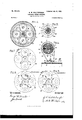
- Figure 1 is a sectional elevation of a gearing embodying one form of my invention applied to a driving-shaft the power from which is transmissible through 0 the said gearing.
- Figs. 2, 3, 4, 5, and 6 are cross-sections taken from correspondinglynumbered lines of the said Fig. 1 looking to the right in each instance.
- Figs. 7, 8, and 9 are diagrams illustrating the operation of the said gearing under different conditions.
- the letterA indicates a rotary shaft, which 0 is the driving-shaft above referred to and which may itself be driven by any suitable engine or motor, the same supplying power to be transmitted by the gearing.
- This shaft may be rotated continuously in one direc- 5 tionfor instance, in the direction indicated by the arrow placed on it in Fig. 1 of this drawings. It is made of two diameters, as shown in the said drawings, which represent it of increased size at the left end, assumed to :be the engine end of the said shaft;
- the said shaft is made advantageously of one uniform size.
- the said shaft A is also shown as being journaled in bearings B at the upper end of short standards C, rising from a base D.
- This construction is suitable; but here again it will be observed that other bearings and supports therefor are within the purview of my invention.
- All power furnished by the engine or motor running the shaft A is transmitted from it, and all motion imparted to the driven parts is received from it through the gearing, which is all on it, without the employment and interposition of any counter-shaft or intermediate shaft, such as is used with other forms of power-transmitting mechanism and changespeed gears.
- E is a pinion which is keyed on the shaft A and revolves therewith when the latter is turning.
- a sleeve F that fits 8o loosely on the said shaft and is provided with a series of radial arms or spider G, forming an integral part of it and carrying spurgears H, in mesh with the said pinion.
- the spur-gears H are mounted on screwbolts I, passing through the several extremities of the spider G, and are normally freeto revolve thereon, being thus adapted to turn both on their own axis and also in a vertical circle having a common center with the pin- 0 ion E and driving-shaft A.
- Four spur-gears H are employed in the form of my invention described in these presents, as indicated in Fig. 4 of the drawings, this being considered the best number to employ to secure perfect 5 equipoise and produce the best results. Nevertheless the number of the said gears may be varied.
- One spur-gear H would be sulficient to carry out the purposes of my invention, and it will therefore be understood that I contemplate the use of any suitable number of such gears without restricting my invention to any particular number, whether one, two, three, four, or more.
- a barrel or drum J Over and around the spur-gears H is placed a barrel or drum J, provided with an internal gear-wheel K, engaged by the said spurgears.
- This barrel extends out both to the right and to the left of the spur-gears H.
- On the right it is made to cover one side of these gears, with their pivots, the spider G of the sleeve F, and a further portion of the said sleeve, on which is fitted loosely a diminished portion or neck L of the said barrel.
- the said barrel On the left the said barrel incloses a plate M and a friction-clutch N.
- the plate M has a suitable aperture in its center, through which the shaft A passes, and it is so fitted behind the clutch N in the barrel J as to completely cover the left side of the pinion E, spur-gears H, and internal gear K therein.
- all the gearing within the said barrelJ is properly housed and confined and well situated for purposes of lubrication, the same being made usually to run in oil, which is poured into the barrel and is thrown out by centrifugal force to the circumference thereof and distributed by the several gears as they are rolling around.
- both the barrel J and sleeve F are geared with the driving-shaftA, and also one with the other, through the medium of the internal gear K, spur-gears II, and pinion E.
- the barrel J is also directly connectible with the said shaft through the agency of the friction-clutch hereinbefore referred to as being within the left end of the said barrel.
- This clutch as represented in Figs. 1 and 2 of the drawings, consists of a pair of half-rings N N, running around close to the inner surface of the barrel J and united at diametrically-opposite ends by a plate 0, fastened to or made integral with one of their edges and having a hub P in its center, through which the shaft A passes.
- the hub P is keyed on the shaft A.
- one of the half-rings N begins at one end of the plate 0 and the other half-ring begins at the other end of 0, each ending near where its mate commences.
- the pair of half-rings thus forms, with the plate, a circle that is parted at two places and the halves of which are held together by a crosspiece. These parts are fitted so that they can turn with the shaft A independently of the barrel J when they are not forced out of their circle; but when forced out or expanded the half-rings N will bind against the inner surface of the barrel and cause the latter to turn with them and with the plate 0 and shaft A through frictional adherence.
- the barrel will then be coupled or connected to the shaft and will revolve therewith at the same rate of axial speed and in the same direction.
- the half-rings N are spread apart whenever it is desired to have the shaft and barrel turn together in this way by means of two levers Q, located at the ends of the plate 0, where the said levers are each held by a pivot-pin R, passing through the said plate and through a lug S, formed on the edge of each half-ring and projecting inwardly from the same.
- the short arms of the levers Q bear against the loose ends of the half-rings N and their long arms rest on opposite sides of a conical collar T, placed on the shaft A and adapted to slide thereon.
- Small bolts U passed through the said long arms of the levers Q and having their heads against the sides of the collar T, are provided to avoid direct contact between the said collar and leverarms, and the same are used also to throw out the said levers farther apart as the halfrings N become worn by friction against the inner surface of the barrel J.
- the collar T can be moved to and fro on the shaft A either to drive the cone part thereof in between the long arms of the levers Q or to withdraw it therefrom through the agency of a hand-le ver V, fulcrumed on a shaft W, journaled in bearings X on the base D.
- the lever V has attached to it a suitably-curved block Y, fitted in a peripheral groove Z of the said collar and operating to shift the latter when the lever is swung either to the right or to the left.
- a suitably-curved block Y fitted in a peripheral groove Z of the said collar and operating to shift the latter when the lever is swung either to the right or to the left.
- Moving in the collar T by placing the hand-lever V in the position represented in Fig. 1 causes the long arms of the levers Q to swing outward, and consequently forces the short arms thereof against the loose ends of the half-rings N, which on spreading apart come into frictional contact with the inner surface of the barrel J, with the result hereinbefore indicated.
- Moving out the collar by pushing the hand-leverin the opposite direction causes a reverse movement of the levers Q by allowing the half-rings to spring back to their normal position, and the barrel J is again uncoupled from the drivingshaft.
- the barrel J is completely independent of the said shaft in this sense, that it may remain stationary while the shaft is in rotation, owing to the spur-gears H, in mesh with the pinion E, being able to turn around the internal gear-wheel K, in which case the sleeve .F will be made to revolve within the said barrel at such speed as the said spur-gears which it carries will roll around the said internal gearwheel, the spur-gears turning on their own axis oppositely to the pinion and also moving in a body together in the same direction as but with less speed than the pinion and shaft, all as indicated in the diagram Fig. 8.
- the rod 4 has nuts 8 on one end to assist in keeping it in proper position and at its other end the said rod is provided with a lever 9, which is connected by a link or bar 10 with another lever 11, secured to an extension of the shaft W of the hand-lever V, previously described. (See Figs. 1, 2, and 3.) Booking the screwrod in one direction through the system of levers thereto connected operates, it will be understood, to tighten the strap by screwing in one of its ends, thereby applying the brakeshoes 1. Rolling the said rod in the opposite direction screws out the same end of the strap and withdraws the brake-shoes.
- the sleeve F can be held in a fixed positionthat is, while the said barrel is freein which case the spur-gears H, carried by the spider G, cause the internal gear-wheelK, and hence the barrel, to revolve in the same direction as themselves, or oppositely to the pinion E and shaft A, as the arrows indicate in the diagram Fig. 9.
- the barrel then moves backward as compared with the direction in which it runs when it is coupled with the shaft A-that is to say, in a reverse direction.
- This back or reverse movement of the barrel is also a slow movement, the speed being at the rate the spurgears H will cause the internal gear-wheel to revolve, which with the size of gears illustrated is one-fourth the speed of the shaft A, the latter making four turns for each revolution of the barrel.
- the sleeve F is held fast, whenever required, preferably by a footbrake consisting of shoes 12, attached to a strap or band 13 and laid between vertical flanges 14 of a brake-wheel 15, fastened, for example, by countersunk screws 16 to the outer end of the said sleeve.
- One end of the strap 13 is attached to a rod l7,passing through lugs 18 on the base D, and the other end of the said strap is pivot-ally connected-for instance, by a bolt or pin 19to a foot-lever 20, fulcrumed on a rod 21, similar to the rod 17, and similarly passed through lugs 22 on the said base.
- a somewhat-difierent form of clutch is used for coupling the sprocketwheel 23 with the sleeve F, the latter-named clutch consisting of a collar 30, loosely fitted on the right-hand end of the shaft A andhaving reciprocating pins or locking members 31, square in cross-section and passing through grooves or holes of same shape formed partly in the sleeve F and partly in the brake-wheel 15 and sprocket-wheel 23 thereon, as shown in Figs. 1 and 6.
- This clutch is moved by a lever 32, pivoted at 33 on the base D and engaging in the usual way a peripheral groove 3k in the collar 30.
- the lever 32 is connected by a link or bar 35 with the handlever 27 of the other clutch on the opposite side of the sprocket-wheel23, so that only one lever need he used to apply either clutch to the sprocket-wheel, and but one clutch can be applied to the latter at any one time.
- the several parts are so arranged that neither clutch is applied, and the sprocket-wheel consequently remains free when the levers are in a vertical position; but pushing the handlever 27 either to the left or to the right applies either clutch to the sprocket-wheel 23.
- pushing it into the position represented in Fig. 1 that is to say, to the left-applies the clutch 30 on the right of the sprocketwheel. To push it in the opposite directionto the rightwould withdraw the clutch 30 and apply instead the other clutch on the left.
- the sprocket-wheel 23 which, as we have seen, receives its motion from either the barrel J or the sleeve F, according as it may be coupled to either, will in turn communicate the motion to any object that it may be connected with to turn or move, as willbe readily comprehended. For example, it will drive a carriage if connected by a chain to another sprocket-wheel secured to the axle for the driving-wheels or to the rear drivingovheels of said carriage. It will likewise run a car with a similar or other suitable form of powertransmitting connection, or a launch by connection with its propeller-shaft, or a tractionengine for road-hauling or plowing, or a motor-truck, &c. Y
- My invention has a wide range of application. Speaking generally, it may be said to be applicable to many difierent types of land and water conveyances, to engines, shafting, and machinery, and to the hauling, raising, or lowering of loads, whether light or heavy.
- the expansion-clutch will be applied to the barrel J, connecting it directly and positively with the driving-shaft, the clutch 30 will be coupling the sprocket-wheel 23 with the sleeve F, and since we have seen that when the expansionclutch is applied all the parts of the gearing become locked together and all move about and with the shaft A, as indicated in the dia gram Fig. 7, the sprocket-wheel 23, coupled with the said sleeve, will also be moving with the other parts in the same direction and at the same rate of speed, which is that of the driving-shaft. The automobile will then be driving at full speed.
- a lever V is kept vertical or in its neutral position, so that neither the expansion-clutch nor the brake may be applied to the barrel J, which thus remains free to turn.
- the foot-brake is applied, so as to hold the sleeve Fstationary, and finally the lever 27 is pushed to the right in order to couple the sprocketwheel 23 with the neck L of the barrel.
- the several parts of the gearing will then move as indicated in the diagram Fig.
- the above-described gearing is adapted to transmit power and motion from a single shaft forward and backward and at three different speeds without in any way altering the rate of movement of the said shaft, its engine or motor, or reversing the same. It provides for two velocities in one direction and another velocity in the opposite directionthat is to say, gives either full or slow speed ahead, at choice, and slow speed backward-while the single shaftkeeps on running continuously in one and the same direction.
- the driven wheel is so located with relation to the gearing that it may be connected to and disconnected from the source of power in an instant through the said gearing.
- a variable-speed gearing consisting of a fixed pinion, on a rotary shaft, combinedwith a sleeve loosely mounted on said shaft and geared with said pinion, a barrel having an 9 internal gear-Wheel in mesh with the gear of said sleeve, means for positively connecting said barrel with said shaft so they willturn together, a loose wheel, and means for coupling said loose wheel to said sleeve, substantially as described.
- a variable-speed gearing comprising a pinion keyed on a shaft that may run continuously in one direction, a sleeve loose on said shaft, geared with said pinion, a barrel provided with an internal gear-wheel meshing with the gear of said sleeve, means for connecting said barrel directly with said shaft and causing it to turn in the same direction, a loose wheel, and means for coupling said loose wheel to said barrel, substantially as de scribed.
- a fixed pinion on a rotary shaft com bined with a sleeve geared with said pinion and loosely mounted on said shaft, a barrel having an internal gear-wheel engaging the gear of said sleeve, means for rigidly connect ing the rotary shaft with said barrel, a loose wheel, and means for coupling said loose wheel either to the sleeve or to the barrel, substantially as described.
- a variable-speed gearing consisting of a fixed pinion on-a single driving-shaft that may run continuously in one direction, a sleeve loosely mounted on said shaft next to said pinion and carrying a set of spur-gears meshing with the same, a barrel loosely mounted on said sleeve and having an internal gearwheel engaged by said spur-gears, a sprocket- Wheel loosely mounted on said sleeve next to said barrel, a clutch adapted to couple the barrel with the driving-shaft, a brake applicable to the barrel, a brake applicable to the sleeve, and clutches for coupling the loose wheel with either the barrel or the. sleeve, substantially as and for the several purposes described.
Landscapes
- Engineering & Computer Science (AREA)
- General Engineering & Computer Science (AREA)
- Mechanical Engineering (AREA)
- Structure Of Transmissions (AREA)
Description
G. w. WALTENBAUGH. Patented July l0, I900.
VARIABLE SPEED GEARING.
(Application filed. Oct. 13, 1899.) (No Model.) 2 Shaets8heet I.
I 12 1e -3 I3 WITNESEEE I NVENTDH W 4 QMMMQM THE Ncnms PETERS co. PHDTO-LKTNO" WASNWGTON. o. r
No. 653,632. Patented July l0, I900.
G. W. WALTE NBAUGH. VARIABLE SPEED BEARING.
. (Application filed. Oct. 18, 1899.)
(No Model.) 2 Sheets-Shani 2.,
WITNEE EE E W g NTTED STATES PATENT Crricn.
GEORGE W. WALTENBAUGH, OF SAN FRANCISCO, CALIFORNIA, ASSIGNOR OF ONE-HALF TO JOSEPH M. OUGH, OF SAME PLACE.
VARIABLE-SPEED GEARING.
SPECIFICATION forming part of Letters Patent No. 653,632, dated July 10, 1900.
Application filed October 18, 1899- Serial No. 733,509. (No model.)
To all whom it may concern:
Be it known that I, GEORGE W. WALTEN- BAUGH, a citizen of the United States of America, and a resident of the city and county of San Francisco, State of California, have in-- vented certain new and useful Improvements in Variable-Speed Gearing, of which the following is a specification.
My invention relates to mechanism for the to transmission of power and motion.
One object of the invention is to provide a gearing capable of producing different velocities and, applying power in different ratios, forward and backward, from a single drivingshaft that may turn continuously in one direction. No counter-shaft is used in my invention.
A further object is to have the gearing so made that the part to be driven thereby will be independent of it normally and may be instantly disconnected from it and the source of power at the will of the operator.
Reference is had to the drawings hereto annexed for a detailed description of my said improvement.
In the said drawings, Figure 1 is a sectional elevation of a gearing embodying one form of my invention applied to a driving-shaft the power from which is transmissible through 0 the said gearing. Figs. 2, 3, 4, 5, and 6 are cross-sections taken from correspondinglynumbered lines of the said Fig. 1 looking to the right in each instance. Figs. 7, 8, and 9 are diagrams illustrating the operation of the said gearing under different conditions.
The same reference-signs are employed to indicate the same parts throughout the speci fication and drawings.
The letterA indicates a rotary shaft, which 0 is the driving-shaft above referred to and which may itself be driven by any suitable engine or motor, the same supplying power to be transmitted by the gearing. This shaft may be rotated continuously in one direc- 5 tionfor instance, in the direction indicated by the arrow placed on it in Fig. 1 of this drawings. It is made of two diameters, as shown in the said drawings, which represent it of increased size at the left end, assumed to :be the engine end of the said shaft;
but this is not an essential feature of my invention, as in practice the said shaft is made advantageously of one uniform size. For purposes of illustration the said shaft A is also shown as being journaled in bearings B at the upper end of short standards C, rising from a base D. This construction is suitable; but here again it will be observed that other bearings and supports therefor are within the purview of my invention. All power furnished by the engine or motor running the shaft A is transmitted from it, and all motion imparted to the driven parts is received from it through the gearing, which is all on it, without the employment and interposition of any counter-shaft or intermediate shaft, such as is used with other forms of power-transmitting mechanism and changespeed gears. By thus eliminating useless or unnecessary shafting and placing the entire gearing on the driving-shaft I make myinvention simpler, lighter, less expensive, and much more compact than would otherwise be the case, and the same can truly be said to be self-contained.
E is a pinion which is keyed on the shaft A and revolves therewith when the latter is turning.
Next to the pinion E, to the right thereof on shaft A, is placed a sleeve F, that fits 8o loosely on the said shaft and is provided with a series of radial arms or spider G, forming an integral part of it and carrying spurgears H, in mesh with the said pinion.
The spur-gears H are mounted on screwbolts I, passing through the several extremities of the spider G, and are normally freeto revolve thereon, being thus adapted to turn both on their own axis and also in a vertical circle having a common center with the pin- 0 ion E and driving-shaft A. Four spur-gears H are employed in the form of my invention described in these presents, as indicated in Fig. 4 of the drawings, this being considered the best number to employ to secure perfect 5 equipoise and produce the best results. Nevertheless the number of the said gears may be varied. One spur-gear H would be sulficient to carry out the purposes of my invention, and it will therefore be understood that I contemplate the use of any suitable number of such gears without restricting my invention to any particular number, whether one, two, three, four, or more.
Over and around the spur-gears H is placed a barrel or drum J, provided with an internal gear-wheel K, engaged by the said spurgears. This barrel extends out both to the right and to the left of the spur-gears H. On the right it is made to cover one side of these gears, with their pivots, the spider G of the sleeve F, and a further portion of the said sleeve, on which is fitted loosely a diminished portion or neck L of the said barrel. On the left the said barrel incloses a plate M and a friction-clutch N. The plate M has a suitable aperture in its center, through which the shaft A passes, and it is so fitted behind the clutch N in the barrel J as to completely cover the left side of the pinion E, spur-gears H, and internal gear K therein. Thus, as will be observed, looking at Fig. 1 of the drawings, all the gearing within the said barrelJ is properly housed and confined and well situated for purposes of lubrication, the same being made usually to run in oil, which is poured into the barrel and is thrown out by centrifugal force to the circumference thereof and distributed by the several gears as they are rolling around. It will further be observed that both the barrel J and sleeve F are geared with the driving-shaftA, and also one with the other, through the medium of the internal gear K, spur-gears II, and pinion E.
Besides being geared or connected indirectly with the shaft A and sleeve F thereon, as above described, the barrel J is also directly connectible with the said shaft through the agency of the friction-clutch hereinbefore referred to as being within the left end of the said barrel. This clutch, as represented in Figs. 1 and 2 of the drawings, consists of a pair of half-rings N N, running around close to the inner surface of the barrel J and united at diametrically-opposite ends by a plate 0, fastened to or made integral with one of their edges and having a hub P in its center, through which the shaft A passes. The hub P is keyed on the shaft A. As will be seen in Fig. 2, one of the half-rings N begins at one end of the plate 0 and the other half-ring begins at the other end of 0, each ending near where its mate commences. The pair of half-rings thus forms, with the plate, a circle that is parted at two places and the halves of which are held together by a crosspiece. These parts are fitted so that they can turn with the shaft A independently of the barrel J when they are not forced out of their circle; but when forced out or expanded the half-rings N will bind against the inner surface of the barrel and cause the latter to turn with them and with the plate 0 and shaft A through frictional adherence. The barrel will then be coupled or connected to the shaft and will revolve therewith at the same rate of axial speed and in the same direction. The half-rings N are spread apart whenever it is desired to have the shaft and barrel turn together in this way by means of two levers Q, located at the ends of the plate 0, where the said levers are each held by a pivot-pin R, passing through the said plate and through a lug S, formed on the edge of each half-ring and projecting inwardly from the same. The short arms of the levers Q bear against the loose ends of the half-rings N and their long arms rest on opposite sides of a conical collar T, placed on the shaft A and adapted to slide thereon. Small bolts U, passed through the said long arms of the levers Q and having their heads against the sides of the collar T, are provided to avoid direct contact between the said collar and leverarms, and the same are used also to throw out the said levers farther apart as the halfrings N become worn by friction against the inner surface of the barrel J. The collar T can be moved to and fro on the shaft A either to drive the cone part thereof in between the long arms of the levers Q or to withdraw it therefrom through the agency of a hand-le ver V, fulcrumed on a shaft W, journaled in bearings X on the base D. The lever V has attached to it a suitably-curved block Y, fitted in a peripheral groove Z of the said collar and operating to shift the latter when the lever is swung either to the right or to the left. Moving in the collar T by placing the hand-lever V in the position represented in Fig. 1 causes the long arms of the levers Q to swing outward, and consequently forces the short arms thereof against the loose ends of the half-rings N, which on spreading apart come into frictional contact with the inner surface of the barrel J, with the result hereinbefore indicated. Moving out the collar by pushing the hand-leverin the opposite direction causes a reverse movement of the levers Q by allowing the half-rings to spring back to their normal position, and the barrel J is again uncoupled from the drivingshaft. The above-described friction-clutch isa known form of clutch, and it is therefore understood that I do not claim the same per se, but only as one of the mechanical elements that go to make up my invention. Nevertheless I do not-restrict my invention to a combination of elements of which the clutch described must be a necessary part, as the same could easily be replaced by some other clutch of difierent kind or type with: out afiecting the operativeness of the combination. Myinventioncomprehendsanysuitable clutch that will establish a connection between the barrel J and rotary shaft A and cause them to turn together, by friction or otherwise, whenever it is applied. The application of the clutch, it is to be noted, also brings about the rotation of the spur-gears H and sleeve F, not independently, but in the same direction and at the same rate of axial speed as the shaft and barrel, because the pinion E and internal gear-wheel K exert then equal power on opposite sides of the ICC said spur-gears and all become locked together, moving as one body with the shaft at the full speed thereof in the manner indicated in the diagram Fig. 7. This is the fast movement of the gearing.
Although geared with the driving-shaft A and also connectible therewith by the clutch N, the barrel J is completely independent of the said shaft in this sense, that it may remain stationary while the shaft is in rotation, owing to the spur-gears H, in mesh with the pinion E, being able to turn around the internal gear-wheel K, in which case the sleeve .F will be made to revolve within the said barrel at such speed as the said spur-gears which it carries will roll around the said internal gearwheel, the spur-gears turning on their own axis oppositely to the pinion and also moving in a body together in the same direction as but with less speed than the pinion and shaft, all as indicated in the diagram Fig. 8. We then have a slow movement of the sleeve and gearing within the barrel, which with the sizes of gears illustrated is calculated to be about five and one-fifth times slower than that of the driving-shaft. The barrel J is held in fixed position to bring about this result by means of a brake (shown in Figs. 1 and 3) and consisting of wooden shoes numbered l, bolted to a strap or band 2 and placed in a circumferential groove or depression of the said barrel within a vertical flange thereof, (indicated by the reference-numeral 3.) The strap 2 is tightened or loosened, as may be required to apply or withdraw the brakeshoes1 ,bya screw-rod 4, fitted in lugs or bearings 5 on the base D and passed through eyes 6, formed in the ends of the said strap. The ends of the strap 2, with the eyes 6 thereof, are within two of the lugs or bearings 5, where an external screw-thread 7, formed on the rod 4, engages a corresponding internal thread in one of the said eyes. The rod 4 has nuts 8 on one end to assist in keeping it in proper position and at its other end the said rod is provided with a lever 9, which is connected by a link or bar 10 with another lever 11, secured to an extension of the shaft W of the hand-lever V, previously described. (See Figs. 1, 2, and 3.) Booking the screwrod in one direction through the system of levers thereto connected operates, it will be understood, to tighten the strap by screwing in one of its ends, thereby applying the brakeshoes 1. Rolling the said rod in the opposite direction screws out the same end of the strap and withdraws the brake-shoes. The screwthreads on the rod and in the eye of the strap engaged thereby are so formed and the several levers are so connected that the strap is tightened and the shoes applied to the barrel J when the hand-leverVis pushed to the left. When, on the contrary, the lever Vis pushed to the right,it releases the barrel by slackening the strap,and consequently removing the brake-shoes. Thus it will be seen that for applying the brake the lever V is handled the reverse from what it is in applying the clutch N, or, rather, that when it is pushed to the left to put on the brake it leaves the clutch in an inoperative or inactive position, whereas when pushed to the right to work the clutch it takes off the brake. This arrangement, it Will be observed, not only simplifies the operation of the mechanism in that only one hand-lever need be manipulated, but it also makes it impossible for the operator through inadvertence or other cause to work the clutch and brake so that one would interfere with the other.
The above-described brake will be found very suitable for holding the barrel J in the manner and for the purpose set forth. However, I may use other forms of brakes in this connection without overstepping the bounds of my invention, and I therefore reserve the right to use any form of brake or other suitable means for keeping the barrelJ fixed, and thereby causing a slow movement of the set of gears and sleeves therein in the same direction as the higher-speeded driving-shaft.
Like the barrel J the sleeve F can be held in a fixed positionthat is, while the said barrel is freein which case the spur-gears H, carried by the spider G, cause the internal gear-wheelK, and hence the barrel, to revolve in the same direction as themselves, or oppositely to the pinion E and shaft A, as the arrows indicate in the diagram Fig. 9. The barrel then moves backward as compared with the direction in which it runs when it is coupled with the shaft A-that is to say, in a reverse direction. This back or reverse movement of the barrel is also a slow movement, the speed being at the rate the spurgears H will cause the internal gear-wheel to revolve, which with the size of gears illustrated is one-fourth the speed of the shaft A, the latter making four turns for each revolution of the barrel. The sleeve F is held fast, whenever required, preferably by a footbrake consisting of shoes 12, attached to a strap or band 13 and laid between vertical flanges 14 of a brake-wheel 15, fastened, for example, by countersunk screws 16 to the outer end of the said sleeve. One end of the strap 13 is attached to a rod l7,passing through lugs 18 on the base D, and the other end of the said strap is pivot-ally connected-for instance, by a bolt or pin 19to a foot-lever 20, fulcrumed on a rod 21, similar to the rod 17, and similarly passed through lugs 22 on the said base.
I have arranged to transmit the power from the shaft A through the gearing aforedescribed to a sprocket wheel 23, loosely mounted on the sleeve F between the brake-- wheel 15 and the diminished end of the barrel J, and connectible at will with either the said barrel or the said sleeve by means of clutches, several forms of which can be used.
To connect the sprocket-wheel 23 with the barrel J in the form of my invention herein disclosed, I have provided the left side of said wheel, as shown in Figs. 1 and 5, with projections 24 and intervening depressions or spaces 25, which engage with similar projections and intervening depressions or spaces on the adjacent side of a collar 26, feathered on the neck L of the said barrel. The collar 26 is moved to and from the sprocket-wheel by a hand-lever 27, engaging a peripheral groove 28 in the said collar and pivoted at 29 on the base D, the same being fitted and working as is usual with the form of clutch here employed. A somewhat-difierent form of clutch is used for coupling the sprocketwheel 23 with the sleeve F, the latter-named clutch consisting of a collar 30, loosely fitted on the right-hand end of the shaft A andhaving reciprocating pins or locking members 31, square in cross-section and passing through grooves or holes of same shape formed partly in the sleeve F and partly in the brake-wheel 15 and sprocket-wheel 23 thereon, as shown in Figs. 1 and 6. This clutch is moved by a lever 32, pivoted at 33 on the base D and engaging in the usual way a peripheral groove 3k in the collar 30. The lever 32 is connected by a link or bar 35 with the handlever 27 of the other clutch on the opposite side of the sprocket-wheel23, so that only one lever need he used to apply either clutch to the sprocket-wheel, and but one clutch can be applied to the latter at any one time. The several parts are so arranged that neither clutch is applied, and the sprocket-wheel consequently remains free when the levers are in a vertical position; but pushing the handlever 27 either to the left or to the right applies either clutch to the sprocket-wheel 23. Thus pushing it into the position represented in Fig. 1that is to say, to the left-applies the clutch 30 on the right of the sprocketwheel. To push it in the opposite directionto the rightwould withdraw the clutch 30 and apply instead the other clutch on the left.
The sprocket-wheel 23, which, as we have seen, receives its motion from either the barrel J or the sleeve F, according as it may be coupled to either, will in turn communicate the motion to any object that it may be connected with to turn or move, as willbe readily comprehended. For example, it will drive a carriage if connected by a chain to another sprocket-wheel secured to the axle for the driving-wheels or to the rear drivingovheels of said carriage. It will likewise run a car with a similar or other suitable form of powertransmitting connection, or a launch by connection with its propeller-shaft, or a tractionengine for road-hauling or plowing, or a motor-truck, &c. Y
My invention has a wide range of application. Speaking generally, it may be said to be applicable to many difierent types of land and water conveyances, to engines, shafting, and machinery, and to the hauling, raising, or lowering of loads, whether light or heavy.
Supposing my invention to be applied to an automobile, its operation will be as follows: First, assuming the driving-shaft A to be continuously running, if we place the levers V and 27 in their vertical or neutral position with the clutches and brakes oil? it will be seen that only such parts as are keyed to the driving-shaft and those immediately dependent thereupon are turning with it. The sprocket-wheel 23 is completely at rest, and so is the automobile. Secondly, if it be desired to go forward and all conditions are favorable for high-speed driving, then by pushing the lever V to the right and the lever 27 to the left, both in the positions given them in Fig. 1 of the drawings, the expansion-clutch will be applied to the barrel J, connecting it directly and positively with the driving-shaft, the clutch 30 will be coupling the sprocket-wheel 23 with the sleeve F, and since we have seen that when the expansionclutch is applied all the parts of the gearing become locked together and all move about and with the shaft A, as indicated in the dia gram Fig. 7, the sprocket-wheel 23, coupled with the said sleeve, will also be moving with the other parts in the same direction and at the same rate of speed, which is that of the driving-shaft. The automobile will then be driving at full speed. It is to be noted that the same effect would be produced by coupling the sprocket-wheel 23 with the barrel J in place of the sleeve F, since all these parts move together in the same direction, in which case the lever 27 would be pushed to the right instead of to the left. I deem it preferable, however, to use the clutch 30 in this instance and couple the sprocket-wheel 23 with the sleeve F in the manner illustrated, owing to certain mechanical advantages that are gained thereby. Thirdly, if, on the contrary, it were desired to start at a moderate speed or conditions were such as to compel travel at a slower rate of motion-for instance, when ascending a grade or hauling a heavy load, conditions that render it advisable to sacrifice speed for a gain of powerthen the lever V is to be worked diEerently. In such case the lever V is pushed to the extreme left to take the expansion-clutch off the inner surface of the barrel J and apply' the brake to the external surface thereof, and the lever 27 is also pushed to the left to couple the sprocket-wheel 23 with the sleeve F. The barrel J being then held stationary, the pinion E will cause the spur-gears H to roll forward around the internal gear K in the direction indicated by the upper arrow in the diagram Fig. 8, and thereby force the sleeve F, through its spider G, to turn also on the shaft A, with the sprocket-wheel 23, in the same direction as the said shaft, but with slower motionthat is, the motion of the sleeve to which the sprocket-wheel is coupled and of the spur-gears in their circular movement within and around the barrel. Fourthly, whenever it is required to reverse the movement or move backward, whether to get out of a hole or to clear an obstruction, &c., the
esaese a lever V is kept vertical or in its neutral position, so that neither the expansion-clutch nor the brake may be applied to the barrel J, which thus remains free to turn. Next the foot-brake is applied, so as to hold the sleeve Fstationary, and finally the lever 27 is pushed to the right in order to couple the sprocketwheel 23 with the neck L of the barrel. The several parts of the gearing will then move as indicated in the diagram Fig. 9, with the barrel revolving oppositely to the driving-shaft, since the spur-gears H in that case are allowed to revolve only on their own axis, owing to the sleeve and its spider being held sta tionary, and the barrel is forced to turn back by the internal gear-wheel K through the action thereon of the said spur-gears. The sprocket-wheel 23 having been coupled to the neck or diminished portion of the barrel turns back with it. This reverse movement of the sprocket-wheel and barrelisequal to the movement of the internal gear-wheel K as the same is caused to revolve by the spurgears H held on the extremities of the spider G of the sleeve F,which is kept from rotating by the foot-brake.
The directions how to handle the two handlevers and the foot-lever to bring about the several results aforesaid may be briefly summarized as follows, to wit: To go ahead at full speed, push the hand-lever V to the right and the lever 27 either to the right or to the left, but preferably to the left, so that the two said levers will be pointed or inclined toward each other, as in Fig. 1 of the drawings. To slow down or go ahead at a reduced or moderate speed, have both levers V and 27 inclined to the left. To back up, keep the lever V upright or in its neutral position, push the lever 27 to the right, and apply the foot-brake. To stop or stand still while the driving-shaft. is running, have the levers in their neutral positionthat is, vertical.
As will be understood, the different movements or speeds above spoken of and of which my improved gearing is capable will vary according to the number of revolutions of the driving-shaft per minute, the relative diameter and number of teeth of the pinion, spurgears, and internal gear-wheel connected with the said shaft, and the size of the sprocketwheel and its ratio to the connecting-wheel on the automobile driven thereby. It is an easy matter then to make the gearing and drive the shaft so as to gain the very highest speed for the vehicle-say forty miles an hour and upwardas well as to obtain various degrees of lower speed both forward and back ward.
The above-described gearing, it will be ob served, is adapted to transmit power and motion from a single shaft forward and backward and at three different speeds without in any way altering the rate of movement of the said shaft, its engine or motor, or reversing the same. It provides for two velocities in one direction and another velocity in the opposite directionthat is to say, gives either full or slow speed ahead, at choice, and slow speed backward-while the single shaftkeeps on running continuously in one and the same direction. At the same time the driven wheel is so located with relation to the gearing that it may be connected to and disconnected from the source of power in an instant through the said gearing. It can be connected either before or after the gearing is set in motion and can be disconnected instantaneously without stopping either the shaft or gearing. There is no further transmission of power after disconnection of the wheel from the gearing, which then becomes loose, and the carriage or engine or machinery that was driven by it can be quickly brought to a stop, though the shaft be running. The power simply remains at hand and is available again at any time either to resume movement in the same direction as before or the reverse, as may be desired.
Having now described my invention, what I claim, and desire to secure by Letters Patent of the United States, is 1. A variable-speed gearing consisting of a fixed pinion, on a rotary shaft, combinedwith a sleeve loosely mounted on said shaft and geared with said pinion, a barrel having an 9 internal gear-Wheel in mesh with the gear of said sleeve, means for positively connecting said barrel with said shaft so they willturn together, a loose wheel, and means for coupling said loose wheel to said sleeve, substantially as described.
2. A variable-speed gearing comprising a pinion keyed on a shaft that may run continuously in one direction, a sleeve loose on said shaft, geared with said pinion, a barrel provided with an internal gear-wheel meshing with the gear of said sleeve, means for connecting said barrel directly with said shaft and causing it to turn in the same direction, a loose wheel, and means for coupling said loose wheel to said barrel, substantially as de scribed.
3. A fixed pinion on a rotary shaft, com bined with a sleeve geared with said pinion and loosely mounted on said shaft, a barrel having an internal gear-wheel engaging the gear of said sleeve, means for rigidly connect ing the rotary shaft with said barrel, a loose wheel, and means for coupling said loose wheel either to the sleeve or to the barrel, substantially as described.
4. The combination, with a rotary shaft, of a pinion fixed thereon, a sleeve loosely mounted on said'shaft and carrying one or more spur-gears in mesh with said pinion, a barrel loosely mounted on said sleeve and having an internal gear-wheel meshing with said spurgear or spur-gears, a clutch for coupling said barrel to the rotary shaft, a wheel loose on the sleeve next to the barrel thereon, and
means for coupling said loose wheel either to the barrel or to the sleeve, substantially as described.
5. The combination, with a single drivingshaft that may turn continuously in one direction, of a loose sleeve and a loose barrel geared with each other and with said shaft, a loose wheel, means for coupling said loose wheel with either the said sleeve or the said barrel, and means for positively connecting the shaft and barrel to cause them to turn together in the same direction, substantially as described.
6. The combination, with a single drivingshaft that may turn continuously in one direction, of a loose barrel and a loose sleeve geared with said shaft and with each other, a loose wheel, means for coupling said loose wheel with said sleeve, and means for holding said barrel stationary while the shaft is turning, substantially as described.
7. The combination, with a single drivingshaft that may turn continuously in one direction, of a loose sleeve and a loose barrel geared with each other and with said shaft, a loose wheel, means for coupling said loose wheel with said barrel, and means for holding said sleeve stationary while the shaft is turning, substantially as described.
8. The combination,with arotary shaft, of a pinion fixed thereon, a sleeve loosely mounted on said shaft and carrying one or more spurgears in mesh with said pinion, a barrel loosely mounted on said sleeve and having an internal gear-wheel engaged by said spurgear or spur-gears, a loose wheel, means for coupling said loose wheel with the sleeve, and a brake for holding the barrel with its internal gear-Wheel stationary while the other gears and shaft are turning therein, substantially as described.
9. The combination,with a rotary shaft, of a fixed pinion thereon, a sleeve loosely mounted on said shaft and carrying one or more spurgears in mesh with said pinion, a barrel loosely mounted on said sleeve and having an internal gear-wheel engaged by said spurgear or spur-gears, a loose wheel, means for coupling said loose Wheel with said barrel, and a brake for holding the sleeve stationary while the barrel and internal gear-wheel revolve around its spur-gear or spur-gears oppositely to the shaft and pinion, substantially as described.
lO. A variable-speed gearing consisting ofa fixed pinion on-a single driving-shaft that may run continuously in one direction, a sleeve loosely mounted on said shaft next to said pinion and carrying a set of spur-gears meshing with the same,a barrel loosely mounted on said sleeve and having an internal gearwheel engaged by said spur-gears, a sprocket- Wheel loosely mounted on said sleeve next to said barrel, a clutch adapted to couple the barrel with the driving-shaft, a brake applicable to the barrel, a brake applicable to the sleeve, and clutches for coupling the loose wheel with either the barrel or the. sleeve, substantially as and for the several purposes described.
Signed by me at San Francisco, California, this 3d day of October, 1899.
GEORGE W. WALTENBAUGII.
Witnesses:
J. M. OUGH, A. H. STE. MARIE.
Priority Applications (1)
| Application Number | Priority Date | Filing Date | Title |
|---|---|---|---|
| US73350999A US653632A (en) | 1899-10-13 | 1899-10-13 | Variable-speed gearing. |
Applications Claiming Priority (1)
| Application Number | Priority Date | Filing Date | Title |
|---|---|---|---|
| US73350999A US653632A (en) | 1899-10-13 | 1899-10-13 | Variable-speed gearing. |
Publications (1)
| Publication Number | Publication Date |
|---|---|
| US653632A true US653632A (en) | 1900-07-10 |
Family
ID=2722201
Family Applications (1)
| Application Number | Title | Priority Date | Filing Date |
|---|---|---|---|
| US73350999A Expired - Lifetime US653632A (en) | 1899-10-13 | 1899-10-13 | Variable-speed gearing. |
Country Status (1)
| Country | Link |
|---|---|
| US (1) | US653632A (en) |
-
1899
- 1899-10-13 US US73350999A patent/US653632A/en not_active Expired - Lifetime
Similar Documents
| Publication | Publication Date | Title |
|---|---|---|
| US1009954A (en) | Speed-changing mechanism. | |
| US653632A (en) | Variable-speed gearing. | |
| US995552A (en) | Transmission-gearing. | |
| US787908A (en) | Automobile drive-gear. | |
| US822453A (en) | Transmission-gear. | |
| US886911A (en) | Variable-speed gear. | |
| US644527A (en) | Reversing-gear. | |
| US791210A (en) | Motor-vehicle. | |
| US778859A (en) | Reversing and variable-speed gear. | |
| US962450A (en) | Shaft-reversing mechanism. | |
| US1232349A (en) | Transmission-gearing. | |
| US725812A (en) | Variable-speed gearing. | |
| US985511A (en) | Change-speed gearing. | |
| US599546A (en) | Power-transmitter | |
| US1250967A (en) | Variable-speed-transmission gearing. | |
| US865449A (en) | Clutch-device power-transmitting mechanism. | |
| US673643A (en) | Power-transmission device. | |
| US1011409A (en) | Gearing. | |
| US285213A (en) | Combined differential gear and frjction-clutch | |
| US721807A (en) | Power-transmitting device. | |
| US706191A (en) | Traction-engine. | |
| US893144A (en) | Variable-speed power-transmission mechanism. | |
| US1025331A (en) | Power-transmission mechanism. | |
| US809337A (en) | Power-transmitting mechanism for motor-vehicles. | |
| US795819A (en) | Variable-speed transmission mechanism. |