US6557676B2 - Innovia vehicle lock-on device - Google Patents
Innovia vehicle lock-on device Download PDFInfo
- Publication number
- US6557676B2 US6557676B2 US09/767,276 US76727601A US6557676B2 US 6557676 B2 US6557676 B2 US 6557676B2 US 76727601 A US76727601 A US 76727601A US 6557676 B2 US6557676 B2 US 6557676B2
- Authority
- US
- United States
- Prior art keywords
- guide
- lock
- rail vehicle
- guide beam
- grounding pad
- Prior art date
- Legal status (The legal status is an assumption and is not a legal conclusion. Google has not performed a legal analysis and makes no representation as to the accuracy of the status listed.)
- Expired - Fee Related
Links
Images


Classifications
-
- B—PERFORMING OPERATIONS; TRANSPORTING
- B62—LAND VEHICLES FOR TRAVELLING OTHERWISE THAN ON RAILS
- B62D—MOTOR VEHICLES; TRAILERS
- B62D1/00—Steering controls, i.e. means for initiating a change of direction of the vehicle
- B62D1/24—Steering controls, i.e. means for initiating a change of direction of the vehicle not vehicle-mounted
- B62D1/26—Steering controls, i.e. means for initiating a change of direction of the vehicle not vehicle-mounted mechanical, e.g. by a non-load-bearing guide
- B62D1/265—Steering controls, i.e. means for initiating a change of direction of the vehicle not vehicle-mounted mechanical, e.g. by a non-load-bearing guide especially adapted for guiding road vehicles carrying loads or passengers, e.g. in urban networks for public transportation
-
- B—PERFORMING OPERATIONS; TRANSPORTING
- B62—LAND VEHICLES FOR TRAVELLING OTHERWISE THAN ON RAILS
- B62D—MOTOR VEHICLES; TRAILERS
- B62D55/00—Endless track vehicles
- B62D55/08—Endless track units; Parts thereof
-
- B—PERFORMING OPERATIONS; TRANSPORTING
- B60—VEHICLES IN GENERAL
- B60L—PROPULSION OF ELECTRICALLY-PROPELLED VEHICLES; SUPPLYING ELECTRIC POWER FOR AUXILIARY EQUIPMENT OF ELECTRICALLY-PROPELLED VEHICLES; ELECTRODYNAMIC BRAKE SYSTEMS FOR VEHICLES IN GENERAL; MAGNETIC SUSPENSION OR LEVITATION FOR VEHICLES; MONITORING OPERATING VARIABLES OF ELECTRICALLY-PROPELLED VEHICLES; ELECTRIC SAFETY DEVICES FOR ELECTRICALLY-PROPELLED VEHICLES
- B60L5/00—Current collectors for power supply lines of electrically-propelled vehicles
- B60L5/38—Current collectors for power supply lines of electrically-propelled vehicles for collecting current from conductor rails
-
- B—PERFORMING OPERATIONS; TRANSPORTING
- B61—RAILWAYS
- B61B—RAILWAY SYSTEMS; EQUIPMENT THEREFOR NOT OTHERWISE PROVIDED FOR
- B61B13/00—Other railway systems
- B61B13/04—Monorail systems
-
- B—PERFORMING OPERATIONS; TRANSPORTING
- B60—VEHICLES IN GENERAL
- B60L—PROPULSION OF ELECTRICALLY-PROPELLED VEHICLES; SUPPLYING ELECTRIC POWER FOR AUXILIARY EQUIPMENT OF ELECTRICALLY-PROPELLED VEHICLES; ELECTRODYNAMIC BRAKE SYSTEMS FOR VEHICLES IN GENERAL; MAGNETIC SUSPENSION OR LEVITATION FOR VEHICLES; MONITORING OPERATING VARIABLES OF ELECTRICALLY-PROPELLED VEHICLES; ELECTRIC SAFETY DEVICES FOR ELECTRICALLY-PROPELLED VEHICLES
- B60L2200/00—Type of vehicles
- B60L2200/26—Rail vehicles
Definitions
- This device not only secures the rail vehicle to the guide beam to inhibit vehicle track jumping and/or roll over, but also serves as a ground collector.
- the lock-on device of the present invention includes a member and a grounding pad.
- a first end of the member is configured to be connected to a guide frame of the rail vehicle.
- the grounding pad is attached to a second end of the member.
- the grounding pad may be attached to the member in any location suitable for collecting ground from the guide beam during use.
- FIG. 1 is a perspective view of a lock-on device
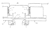
- FIG. 2 is a front view of the lock-on device of FIG. 1 installed on a rail vehicle;
- FIG. 3 is a bottom schematic illustration of several lock-on devices of FIG. 1 installed on a rail vehicle.
- the member 12 preferably includes a first portion 20 , a second portion 22 , and at least one spring assembly 24 .
- the first portion 20 includes the first end 16 that connects to the guide frame 64 .
- the second portion 22 includes the second end 18 to which the grounding pad 14 attaches.
- the at least one spring assembly 24 interconnects the first portion 20 and the second portion 22 and biases the grounding pad 14 against the guide beam 44 in order to ensure that the grounding pad 14 properly engages the guide beam 44 .
- the at least one spring assembly 24 may include a bolt and nut 26 to adjust the tension in a spring 28 of the at least one spring assembly 24 .
- the member 12 may also include a third portion 30 .
- the at least one spring assembly 24 is positioned between a flange 32 of the first portion 20 and a flange 34 of the second portion 22 .
- the second portion 22 further includes a slot 36 and the third portion 30 includes a key 38 configured to be insertable into and slideably movable within the slot 36 of the second portion 22 .
- the slot 36 receives the key 38 on a first surface 40 of the second portion 22 .
- the third portion 30 is attached, using conventional methods, to the first portion 20 that is positioned on a second surface 42 of the second portion 22 , thus sandwiching the second portion 22 between the first portion 20 and the third portion 30 .
- the key 38 slides within the slot 36 permitting the spring 28 to vary in tension, thereby biasing the grounding pad 14 against the guide beam 44 .
- Each guide assembly 62 includes a guide frame 64 and four guide wheels 52 configured to engage the guide beam 44 located in a guide way 66 on which the rail vehicle 56 travels.
- One guide assembly 62 is located near each end 68 of the rail vehicle 56 (more or less than two guide assemblies 62 may be present on the rail vehicle 56 ).
- At least one pair of lock-on devices 10 is installed on each guide assembly 62 . Given one pair of lock-on devices 10 installed on the rail vehicle 56 as shown in FIG.
- one lock-on device 10 is positioned on each side of the guide frame 64 between the guide wheels 52 , preferably substantially at the mid-point between the guide wheels 52 .
- the first end 16 of the member 12 is attached to the guide frame 64 such that the grounding pad 14 engages the guide beam 44 at the lower lip 58 of the flange 48 .
- the first end 16 may be attached to the guide frame 64 by any conventional attachment methods, for example, bolt and nut.
- the present invention maintains the rail vehicle 56 on the guide beam 44 during high winds, an accident, or other phenomenon that would traditionally cause the rail vehicle 44 to jump track and/or roll over.
- This is accomplished by having a lock-on device 10 installed on both sides of the guide beam 44 .
- the lock-on device 10 on each side is connected to the rail vehicle 56 through the guide frame 64 and engages the lower lips 58 of the flanges 48 through the grounding pads 14 . If something were to exert a force on the rail vehicle 56 to tend it to roll, this configuration and placement of the lock-on devices 10 prevents any disengagement with the guide beam 44 .
- a force to the left would tend the rail vehicle 56 to tip left which causes the lock-on device 10 on the right to grab the flange 48 of the guide beam 44 to prevent tipping, and vice versa.
- the substantially constant engagement of the grounding pads 14 with the guide beam 44 provides a source of ground for the system.
Landscapes
- Engineering & Computer Science (AREA)
- Transportation (AREA)
- Mechanical Engineering (AREA)
- Chemical & Material Sciences (AREA)
- Combustion & Propulsion (AREA)
- Power Engineering (AREA)
- Platform Screen Doors And Railroad Systems (AREA)
- Handcart (AREA)
- Steering Controls (AREA)
- Train Traffic Observation, Control, And Security (AREA)
- Acyclic And Carbocyclic Compounds In Medicinal Compositions (AREA)
- Transition And Organic Metals Composition Catalysts For Addition Polymerization (AREA)
- Vehicle Body Suspensions (AREA)
- Refuge Islands, Traffic Blockers, Or Guard Fence (AREA)
- Elimination Of Static Electricity (AREA)
- Fittings On The Vehicle Exterior For Carrying Loads, And Devices For Holding Or Mounting Articles (AREA)
- Package Frames And Binding Bands (AREA)
Priority Applications (10)
| Application Number | Priority Date | Filing Date | Title |
|---|---|---|---|
| US09/767,276 US6557676B2 (en) | 2001-01-23 | 2001-01-23 | Innovia vehicle lock-on device |
| AU10210/02A AU777002B2 (en) | 2001-01-23 | 2002-01-18 | Innovia vehicle lock-on device |
| KR1020020003508A KR100569743B1 (ko) | 2001-01-23 | 2002-01-22 | 차량 결합장치 |
| CA002368921A CA2368921C (en) | 2001-01-23 | 2002-01-22 | Device for securing a rail vehicle to a guide beam |
| EP02090031A EP1225081B1 (de) | 2001-01-23 | 2002-01-23 | Gleitende Halterung an der Führungsschiene für spurgeführte Radfahrzeuge |
| SG200200367A SG105529A1 (en) | 2001-01-23 | 2002-01-23 | Innovia vehicle lock-on device |
| DE60205512T DE60205512T2 (de) | 2001-01-23 | 2002-01-23 | Gleitende Halterung an der Führungsschiene für spurgeführte Radfahrzeuge |
| MXPA02000824A MXPA02000824A (es) | 2001-01-23 | 2002-01-23 | Dispositivo innovador de inmovilizacion de vehiculo. |
| AT02090031T ATE302129T1 (de) | 2001-01-23 | 2002-01-23 | Gleitende halterung an der führungsschiene für spurgeführte radfahrzeuge |
| HK02109297.9A HK1049314B (en) | 2001-01-23 | 2002-12-23 | Sliding lock-on device engaging the guide beam for track-bound wheeled vehicles |
Applications Claiming Priority (1)
| Application Number | Priority Date | Filing Date | Title |
|---|---|---|---|
| US09/767,276 US6557676B2 (en) | 2001-01-23 | 2001-01-23 | Innovia vehicle lock-on device |
Publications (2)
| Publication Number | Publication Date |
|---|---|
| US20020096413A1 US20020096413A1 (en) | 2002-07-25 |
| US6557676B2 true US6557676B2 (en) | 2003-05-06 |
Family
ID=25079003
Family Applications (1)
| Application Number | Title | Priority Date | Filing Date |
|---|---|---|---|
| US09/767,276 Expired - Fee Related US6557676B2 (en) | 2001-01-23 | 2001-01-23 | Innovia vehicle lock-on device |
Country Status (9)
| Country | Link |
|---|---|
| US (1) | US6557676B2 (de) |
| EP (1) | EP1225081B1 (de) |
| KR (1) | KR100569743B1 (de) |
| AT (1) | ATE302129T1 (de) |
| AU (1) | AU777002B2 (de) |
| CA (1) | CA2368921C (de) |
| DE (1) | DE60205512T2 (de) |
| MX (1) | MXPA02000824A (de) |
| SG (1) | SG105529A1 (de) |
Families Citing this family (4)
| Publication number | Priority date | Publication date | Assignee | Title |
|---|---|---|---|---|
| DE102013100019A1 (de) * | 2013-01-02 | 2014-07-03 | Conductix-Wampfler Gmbh | Zustelleinheit zur Positionierung einer Stromabnehmereinheit |
| CN110155106B (zh) * | 2018-05-21 | 2020-06-19 | 比亚迪股份有限公司 | 防侧翻装置、转向架、轨道车辆以及轨道交通系统 |
| CN110871691B (zh) * | 2018-08-31 | 2022-03-18 | 比亚迪股份有限公司 | 受流器及车辆的供电系统 |
| CN111231685B (zh) * | 2018-11-29 | 2022-04-15 | 比亚迪股份有限公司 | 用于轨道车辆的充电系统 |
Citations (21)
| Publication number | Priority date | Publication date | Assignee | Title |
|---|---|---|---|---|
| US327381A (en) * | 1885-09-29 | Third to samuel g | ||
| US332926A (en) * | 1885-12-22 | James f | ||
| US356579A (en) * | 1887-01-25 | Electric locomotive | ||
| US936682A (en) | 1905-03-09 | 1909-10-12 | James N Vandegrift | Motor-cycle-railway system. |
| US1623920A (en) | 1925-12-16 | 1927-04-05 | American Monorail Co | Electrified monorail system |
| US2903526A (en) * | 1956-10-16 | 1959-09-08 | Sr Ralph Franklin Mattox | Transportation system |
| US3006286A (en) * | 1961-10-31 | Amusement vehicle apparatus | ||
| US3715991A (en) | 1970-09-04 | 1973-02-13 | T Boyd | Monorail guided electric airplane |
| US4015537A (en) | 1975-06-09 | 1977-04-05 | Diebold, Incorporated | Interior railway transportation system |
| US4043436A (en) * | 1976-05-06 | 1977-08-23 | Westinghouse Electric Corporation | Support apparatus for electrically conductive rail |
| US4089272A (en) * | 1976-11-22 | 1978-05-16 | Westinghouse Electric Corp. | Transportation vehicle guidance apparatus |
| US4207821A (en) | 1977-09-29 | 1980-06-17 | Bleitchert Forderanlagen Gmbh | Monorail conveyor |
| US4888454A (en) * | 1987-06-09 | 1989-12-19 | Daimler-Benz Ag | Current supply system for track-guidable, rubber-tired, electrically propulsive vehicles |
| US5174217A (en) | 1989-01-19 | 1992-12-29 | Nakanishi Metal Works Co., Ltd. | Conveyor having self-propelled carriers with a first motor for high speed driving and a second motor for low speed driving |
| US5289778A (en) | 1992-07-06 | 1994-03-01 | Romine Richard A | Automated electric transportation system |
| US5421268A (en) | 1993-11-17 | 1995-06-06 | Evana Automation | Conveying system |
| US5511488A (en) | 1994-04-25 | 1996-04-30 | Powell; James R. | Electromagnetic induction ground vehicle levitation guideway |
| US5592883A (en) | 1994-05-16 | 1997-01-14 | Andress, Iii; F. Jay | Monorail transportation system and vehicle for traveling thereon |
| US5669472A (en) * | 1996-06-04 | 1997-09-23 | Azzouni; Ghassan H. | Contact shoe assembly for a train |
| US6070703A (en) * | 1998-07-02 | 2000-06-06 | Azzouni; Ghassan Hassan | Adjustable contact shoe assembly for a train |
| US6129028A (en) * | 1998-10-13 | 2000-10-10 | Shaw; John B. | Electrically powered transit car |
Family Cites Families (3)
| Publication number | Priority date | Publication date | Assignee | Title |
|---|---|---|---|---|
| DE133314C (de) * | ||||
| US2226432A (en) * | 1939-03-11 | 1940-12-24 | John O Heinze | Rapid transit elevated structure |
| KR0118142Y1 (ko) * | 1994-03-16 | 1998-07-15 | 황무영 | 모노카트시스템용 모노레일 |
-
2001
- 2001-01-23 US US09/767,276 patent/US6557676B2/en not_active Expired - Fee Related
-
2002
- 2002-01-18 AU AU10210/02A patent/AU777002B2/en not_active Ceased
- 2002-01-22 KR KR1020020003508A patent/KR100569743B1/ko not_active Expired - Fee Related
- 2002-01-22 CA CA002368921A patent/CA2368921C/en not_active Expired - Fee Related
- 2002-01-23 MX MXPA02000824A patent/MXPA02000824A/es active IP Right Grant
- 2002-01-23 AT AT02090031T patent/ATE302129T1/de not_active IP Right Cessation
- 2002-01-23 DE DE60205512T patent/DE60205512T2/de not_active Expired - Lifetime
- 2002-01-23 EP EP02090031A patent/EP1225081B1/de not_active Expired - Lifetime
- 2002-01-23 SG SG200200367A patent/SG105529A1/en unknown
Patent Citations (21)
| Publication number | Priority date | Publication date | Assignee | Title |
|---|---|---|---|---|
| US327381A (en) * | 1885-09-29 | Third to samuel g | ||
| US332926A (en) * | 1885-12-22 | James f | ||
| US356579A (en) * | 1887-01-25 | Electric locomotive | ||
| US3006286A (en) * | 1961-10-31 | Amusement vehicle apparatus | ||
| US936682A (en) | 1905-03-09 | 1909-10-12 | James N Vandegrift | Motor-cycle-railway system. |
| US1623920A (en) | 1925-12-16 | 1927-04-05 | American Monorail Co | Electrified monorail system |
| US2903526A (en) * | 1956-10-16 | 1959-09-08 | Sr Ralph Franklin Mattox | Transportation system |
| US3715991A (en) | 1970-09-04 | 1973-02-13 | T Boyd | Monorail guided electric airplane |
| US4015537A (en) | 1975-06-09 | 1977-04-05 | Diebold, Incorporated | Interior railway transportation system |
| US4043436A (en) * | 1976-05-06 | 1977-08-23 | Westinghouse Electric Corporation | Support apparatus for electrically conductive rail |
| US4089272A (en) * | 1976-11-22 | 1978-05-16 | Westinghouse Electric Corp. | Transportation vehicle guidance apparatus |
| US4207821A (en) | 1977-09-29 | 1980-06-17 | Bleitchert Forderanlagen Gmbh | Monorail conveyor |
| US4888454A (en) * | 1987-06-09 | 1989-12-19 | Daimler-Benz Ag | Current supply system for track-guidable, rubber-tired, electrically propulsive vehicles |
| US5174217A (en) | 1989-01-19 | 1992-12-29 | Nakanishi Metal Works Co., Ltd. | Conveyor having self-propelled carriers with a first motor for high speed driving and a second motor for low speed driving |
| US5289778A (en) | 1992-07-06 | 1994-03-01 | Romine Richard A | Automated electric transportation system |
| US5421268A (en) | 1993-11-17 | 1995-06-06 | Evana Automation | Conveying system |
| US5511488A (en) | 1994-04-25 | 1996-04-30 | Powell; James R. | Electromagnetic induction ground vehicle levitation guideway |
| US5592883A (en) | 1994-05-16 | 1997-01-14 | Andress, Iii; F. Jay | Monorail transportation system and vehicle for traveling thereon |
| US5669472A (en) * | 1996-06-04 | 1997-09-23 | Azzouni; Ghassan H. | Contact shoe assembly for a train |
| US6070703A (en) * | 1998-07-02 | 2000-06-06 | Azzouni; Ghassan Hassan | Adjustable contact shoe assembly for a train |
| US6129028A (en) * | 1998-10-13 | 2000-10-10 | Shaw; John B. | Electrically powered transit car |
Also Published As
| Publication number | Publication date |
|---|---|
| ATE302129T1 (de) | 2005-09-15 |
| AU1021002A (en) | 2002-07-25 |
| EP1225081B1 (de) | 2005-08-17 |
| HK1049314A1 (en) | 2003-05-09 |
| CA2368921A1 (en) | 2002-07-23 |
| CA2368921C (en) | 2007-03-06 |
| KR20020062693A (ko) | 2002-07-29 |
| MXPA02000824A (es) | 2003-08-20 |
| DE60205512D1 (de) | 2005-09-22 |
| AU777002B2 (en) | 2004-09-30 |
| US20020096413A1 (en) | 2002-07-25 |
| EP1225081A2 (de) | 2002-07-24 |
| KR100569743B1 (ko) | 2006-04-11 |
| DE60205512T2 (de) | 2006-06-22 |
| SG105529A1 (en) | 2004-08-27 |
| EP1225081A3 (de) | 2002-07-31 |
Similar Documents
| Publication | Publication Date | Title |
|---|---|---|
| CN1066227C (zh) | 运送和装卸长钢轨用的钢轨装载列车 | |
| US8261671B2 (en) | Bogie lateral movement-limiting system | |
| US4802622A (en) | Single track mobile storage structure and method | |
| EP1225081B1 (de) | Gleitende Halterung an der Führungsschiene für spurgeführte Radfahrzeuge | |
| CA1089943A (en) | Support apparatus for electrically conductive rail | |
| HK1049314B (en) | Sliding lock-on device engaging the guide beam for track-bound wheeled vehicles | |
| CN216915868U (zh) | 一种清扫摆渡车及光伏清洁装置 | |
| JP2689036B2 (ja) | 第3軌條用集電装置 | |
| KR102276211B1 (ko) | 매립형 궤도용 복선기장치 | |
| RU2105833C1 (ru) | Способ определения координат мест присоединения средств крепления к несущей железнодорожной конструкции и устройство для подготовки к установке средств крепления рабочих элементов на несущую железнодорожную конструкцию | |
| JP2002226160A (ja) | エレベータ綱車の舵取り角調整装置 | |
| CA1190272A (en) | Wear plate for idler slide mounting | |
| CN215436442U (zh) | 一种双轨探伤装置 | |
| CN109733990A (zh) | 一种轨道固定装置 | |
| CN220410546U (zh) | 索道车行走轮组及索道车 | |
| GB1566066A (en) | Road track vehicle | |
| GB2194781A (en) | Mobile storage systems | |
| CN107381346B (zh) | 一种水平轮组 | |
| EP0650863B1 (de) | Fahrleitungsstützpunkt | |
| CN222455705U (zh) | 一种用于agv小车通过平车轨道轮缘槽障碍的辅助装置 | |
| JP4508677B2 (ja) | ガイドレールと給電線の取付構造 | |
| JPH08143259A (ja) | マンコンベアのレール | |
| KR102308680B1 (ko) | 매립형 궤도용 탈선 복구 장치 | |
| CN220352521U (zh) | 槽型钢轨护轨结构及轨道 | |
| JP2025077502A (ja) | 軌陸車鉄輪規制器具 |
Legal Events
| Date | Code | Title | Description |
|---|---|---|---|
| AS | Assignment |
Owner name: DAIMLERCHRYSLER RAIL SYSTEMS (TECHNOLOGY), PENNSYL Free format text: ASSIGNMENT OF ASSIGNORS INTEREST;ASSIGNOR:HOLUKA, ROBERT P.;REEL/FRAME:011492/0464 Effective date: 20010112 |
|
| FEPP | Fee payment procedure |
Free format text: PAYOR NUMBER ASSIGNED (ORIGINAL EVENT CODE: ASPN); ENTITY STATUS OF PATENT OWNER: LARGE ENTITY |
|
| FEPP | Fee payment procedure |
Free format text: PAT HOLDER NO LONGER CLAIMS SMALL ENTITY STATUS, ENTITY STATUS SET TO UNDISCOUNTED (ORIGINAL EVENT CODE: STOL); ENTITY STATUS OF PATENT OWNER: LARGE ENTITY |
|
| FPAY | Fee payment |
Year of fee payment: 4 |
|
| FPAY | Fee payment |
Year of fee payment: 8 |
|
| SULP | Surcharge for late payment |
Year of fee payment: 7 |
|
| REMI | Maintenance fee reminder mailed | ||
| LAPS | Lapse for failure to pay maintenance fees | ||
| STCH | Information on status: patent discontinuation |
Free format text: PATENT EXPIRED DUE TO NONPAYMENT OF MAINTENANCE FEES UNDER 37 CFR 1.362 |
|
| STCH | Information on status: patent discontinuation |
Free format text: PATENT EXPIRED DUE TO NONPAYMENT OF MAINTENANCE FEES UNDER 37 CFR 1.362 |
|
| FP | Lapsed due to failure to pay maintenance fee |
Effective date: 20150506 |