US6575672B1 - Superfinishing tool - Google Patents
Superfinishing tool Download PDFInfo
- Publication number
- US6575672B1 US6575672B1 US09/423,309 US42330999A US6575672B1 US 6575672 B1 US6575672 B1 US 6575672B1 US 42330999 A US42330999 A US 42330999A US 6575672 B1 US6575672 B1 US 6575672B1
- Authority
- US
- United States
- Prior art keywords
- tool according
- microfinishing
- bore
- taper
- taper screw
- Prior art date
- Legal status (The legal status is an assumption and is not a legal conclusion. Google has not performed a legal analysis and makes no representation as to the accuracy of the status listed.)
- Expired - Lifetime
Links
Images


Classifications
-
- B—PERFORMING OPERATIONS; TRANSPORTING
- B23—MACHINE TOOLS; METAL-WORKING NOT OTHERWISE PROVIDED FOR
- B23D—PLANING; SLOTTING; SHEARING; BROACHING; SAWING; FILING; SCRAPING; LIKE OPERATIONS FOR WORKING METAL BY REMOVING MATERIAL, NOT OTHERWISE PROVIDED FOR
- B23D77/00—Reaming tools
- B23D77/006—Reaming tools with means for lubricating or cooling
-
- B—PERFORMING OPERATIONS; TRANSPORTING
- B23—MACHINE TOOLS; METAL-WORKING NOT OTHERWISE PROVIDED FOR
- B23D—PLANING; SLOTTING; SHEARING; BROACHING; SAWING; FILING; SCRAPING; LIKE OPERATIONS FOR WORKING METAL BY REMOVING MATERIAL, NOT OTHERWISE PROVIDED FOR
- B23D77/00—Reaming tools
- B23D77/06—Reaming with means for compensating wear
- B23D77/10—Reaming with means for compensating wear by expanding a tube-like non-slotted part of the tool body
-
- Y—GENERAL TAGGING OF NEW TECHNOLOGICAL DEVELOPMENTS; GENERAL TAGGING OF CROSS-SECTIONAL TECHNOLOGIES SPANNING OVER SEVERAL SECTIONS OF THE IPC; TECHNICAL SUBJECTS COVERED BY FORMER USPC CROSS-REFERENCE ART COLLECTIONS [XRACs] AND DIGESTS
- Y10—TECHNICAL SUBJECTS COVERED BY FORMER USPC
- Y10T—TECHNICAL SUBJECTS COVERED BY FORMER US CLASSIFICATION
- Y10T408/00—Cutting by use of rotating axially moving tool
- Y10T408/44—Cutting by use of rotating axially moving tool with means to apply transient, fluent medium to work or product
- Y10T408/45—Cutting by use of rotating axially moving tool with means to apply transient, fluent medium to work or product including Tool with duct
- Y10T408/455—Conducting channel extending to end of Tool
-
- Y—GENERAL TAGGING OF NEW TECHNOLOGICAL DEVELOPMENTS; GENERAL TAGGING OF CROSS-SECTIONAL TECHNOLOGIES SPANNING OVER SEVERAL SECTIONS OF THE IPC; TECHNICAL SUBJECTS COVERED BY FORMER USPC CROSS-REFERENCE ART COLLECTIONS [XRACs] AND DIGESTS
- Y10—TECHNICAL SUBJECTS COVERED BY FORMER USPC
- Y10T—TECHNICAL SUBJECTS COVERED BY FORMER US CLASSIFICATION
- Y10T408/00—Cutting by use of rotating axially moving tool
- Y10T408/83—Tool-support with means to move Tool relative to tool-support
- Y10T408/85—Tool-support with means to move Tool relative to tool-support to move radially
- Y10T408/858—Moving means including wedge, screw or cam
- Y10T408/8588—Axially slidable moving-means
- Y10T408/85892—Screw driven wedge or cam
- Y10T408/85895—Traveling wedge
- Y10T408/858957—Having externally threaded shank connected to tool-support
Definitions
- the invention relates to a microfinishing tool comprising a shank, at least one rigid cutter, as well as at least one guide rib on the periphery and a taper screw by means of which the cutting diameter can be adjusted.
- Such tools are used especially as reamers.
- the reamer is provided with a central coolant bore which divides into two diverging branch bores skirting the shank of the taper screw at a shallow angle.
- the taper extends only over the forward cutting region, so that upon adjustment only the forward portion of the reamer is expanded.
- a reamer is provided with a cutting head expansible by a taper screw and with a coolant passage leading axially through the reamer shaft, with the coolant passage extending into a threaded bore receiving the threaded shank of the taper screw and subsequent to this passing into a hollow cylindrical part of the reamer shaft which is expansible by the taper screw.
- an annular channel which is connected with the axial coolant passage by means of an axially parallel coolant passage in the taper screw. From the annular passage leads at least one channel between the cutters, with this channel or channels being directed forwards at an angle of between 30° and 45°.
- CH-PS 645 051 describes an adjustable machine reamer with taper screw which comprises adjustment means for changing the spacing of the cutters and the guide ribs from the reamer axis in the same sense and to approximately the same degree. Again, the adjustment taper extends only over the forward cutting region.
- microfinishing tool as defined herein.
- a microfinishing tool which has an expandable taper insert which is longer than the cutter.
- the taper insert is seated in an axial blind bore of the tool shank and has a cylindrical recess in its front end.
- a radial slot extends from the front end approximately up to the level of the end of the blind bore.
- a radial screw which is in contact with the taper insert.
- a microfinishing tool in accordance with the invention thus comprises a shank, at least one rigid cutter, at least one guide rib on the periphery and a taper screw by means of which the cutting diameter can be adjusted.
- the taper region of the taper screw is at least equal in length to the cutter.
- tape screw used herein should be understood to include all other expansion parts and arrangements with varying diameter which will achieve the desired expansion effect.
- recesses are provided in the shank of suitable shape to serve as expansion aids in the adjustment of the cutting diameter.
- the microfinishing tool has a quiet, stable mode of operation in spite of high speeds of rotation and/or hardness of the workpiece, over its whole diameter range.
- at least one guide rib is provided per cutter.
- a guide rib can be arranged axially offset in relation to the associated cutter.
- the cutter and/or at least one guide rib can be made as one piece with the shank as a solid tool.
- the manufacture of the tool as a solid tool is very advantageous, particularly in solid hard metal.
- the cutters and/or guide ribs can be inserted, or alternatively the cutters can be soldered on.
- the different pressure points of the taper screw make it possible to adjust the cutters and guide ribs in a defined way.
- the pressure points can be located at different diameters and axial positions of the taper screws and thus a desired axial region of the cutters or guide ribs.
- the material of the cutters and guide ribs can be chosen so as to be matched to the particular requirements of use, independently of the tool body.
- guide ribs with minimum lubrication and for high speeds of rotation are preferably made of diamond.
- a variation of the taper screw comprises tapered sections having different angles of taper. In this way, the enlargement of the diameter can be effected in steps.
- the taper screw can alternatively be made as a multi-part component.
- the taper screw includes a cylindrical section after the threaded region, with this cylindrical section being a snug fit in the shank of the tool. This effects a guidance and alignment of the taper screw and consequently gives an extraordinarily precise, centered expansion of the cutting region, if wanted.
- the microfinishing tool according to the invention can be provided with internal cooling for coolant and/or lubricant, which is guided in particular to the cutting zone.
- This internal cooling is provided for example as a central axial coolant bore in the tool shank for coolant and/or lubricant. From the central axial coolant bore, at least one branch bore leads outwardly into its forward region. In one embodiment of the internal cooling, the branch bore leads into a coaxial supply bore which extends axially at least partially over the cutting region and from which at least one discharge bore leads to the cutting region.
- coolant and lubricant having 10% or more of an oil-containing emulsion is particularly suitable.
- coolant and lubricant can be supplied to the cutting zone even if the tool shank has been expanded for example by a taper screw or if several cutters or adjustable cutters are provided.
- the bore which carries the coolant and lubricant runs through into the forward or cutting region either through a possibly provided taper screw or its receiving passage, so that there is no weakening of the material at this position. Rather, the bore extends coaxially into the cutting region and then in the radial direction in the region of the cutters and guide ribs which are to be cooled or to be lubricated.
- the bore geometry is very simple and consequently can be effected at low cost for the most varied types of friction, sinking and boring tools, even without taper screws.
- the cooling effect of the coaxial bore feeding the coolant through the tool shank can also be utilised.
- the bore arrangement of the present invention makes it possible to cool and to lubricate even the guide ribs of such a tool, so that one ensures a smooth and trouble-free operation of the tool.
- a discharge bore is associated with each guide rib.
- the coolant and lubricant can be supplied as desired, and the intermediate spaces between the guide ribs can be cleaned effectively of any remaining chip material, etc.
- the coaxial supply bore extends over the whole length of the cutting region.
- the coolant and lubricant are distributed over the whole cutting region and are supplied to the cutters or guide ribs at desired positions by way of the discharge bores.
- a particularly good cooling and lubricating effect is achieved in the microfinishing tool according to the invention if a plurality of axially offset discharge bores are provided.
- the number and axial arrangement of the discharge bores can be chosen according to the mechanical and thermal load of the cutting region which is anticipated.
- the discharge bore issues into the chip space of an associated cutter.
- the coolant and lubricant goes directly to the cutter to be cooled and the chip material can be freed and carried away.
- the discharge bore associated with the guide rib leads outwards in the direction of rotation in advance of the guide rib, i.e. the coolant and lubricant goes directly to the associated guide rib.
- the branch bore is directed at an angle forwards.
- the coolant and lubricant stream can thus be directed to the cutting tip in a particularly simple manner.
- the branch bore and/or discharge bore associated with the guide rib has a smaller diameter than the bore associated with the cutter. In this way the cutter, which is subject to mechanically higher loads, is supplied with more coolant than the guide rib.
- the microfinishing tool in accordance with the invention can be provided with one or more rigid cutters. It can also have one or more replaceable cutters and/or cutters mounted on a carrier.
- the cutter or cutters can be adjustable, i.e. it or they can be provided with a pre-cutting step.
- an end cutter or an end cutting zone can be provided.
- the taper screw can close off the axial coolant channel by its threaded end. This simplifies the manufacture of the tool, because the central bore for the cooling channel is then bored through right up to the tapered bore.
- a matching to different cutter and guide rib shapes can advantageously be achieved if the taper screw has taper sections with different angles of taper.
- the cutters and guide ribs can be adjusted thus defined.
- the axial coolant bore can issue into a distribution ring which is in front of the end of the taper screw opposite to the tip of the tool, and from which distribution ring the branch bores extend.
- Suitable materials for the cutters of the microfinishing tool according to the invention are for example hard metal, cermet, ceramic, polycrystalline, natural or synthetic diamond, as thin film and thick film, or cubic boron nitride.
- the guide ribs can consist of for example hard metal, cermet, ceramic, polycrystalline, natural or synthetic diamond, with or without coating.
- the cutting head In the microfinishing tool according to the invention one can arrange for the cutting head to be replaceable. In this way the tool can be utilised in a very versatile manner.
- the cutting head is fixed to the shank of the tool by means of a bayonet connection, or alternatively by means of a taper screw.
- a bayonet connection or alternatively by means of a taper screw.
- other adaptor connections are also possible.
- the microfinishing tool according to the invention can have one, two, three or more cutters.
- At least one guide rib per cutter is provided.
- two guide ribs per cutter are provided.
- the guide ribs are preferably provided between the cutters at the periphery.
- a guide rib can be arranged axially offset relative to the associated cutter. In this way, the number of guide ribs per cutter and the desired guiding effect can be maintained in spite of greater numbers of cutters, and so a quiet, stable operation of the tool can be guaranteed in spite of high speeds of rotation and/or workpieces which are very hard.
- FIG. 1A is an end view of a first embodiment of microfinishing tool according to the invention, of solid material with taper screw, one cutter and three guide ribs,
- FIG. 1B is an end view of a second embodiment of microfinishing tool according to the invention, of solid material with taper screw, one cutter and two guide ribs,
- FIG. 2A is an end view of a third embodiment of microfinishing tool according to the invention, with taper screw, one soldered cutter and three inserted guide ribs,
- FIG. 2B is an end view of a fourth embodiment of microfinishing tool according to the invention, with taper screw, one soldered cutter and two inserted guide ribs,
- FIG. 3A is an end view of a fifth embodiment of microfinishing tool according to the invention, with taper screw, expansion aid, one soldered cutter and three inserted guide ribs,
- FIG. 3B is an end view of a sixth embodiment of microfinishing tool according to the invention, with taper screw, expansion aid, one soldered cutter and two inserted guide ribs,
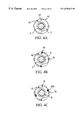
- FIG. 4A is an end view of a seventh embodiment of microfinishing tool according to the invention, of solid material with taper screw, two cutters and four guide ribs,
- FIG. 4B is an end view of an eighth embodiment of microfinishing tool according to the invention, with taper screw, two soldered cutters and four inserted guide ribs,
- FIG. 4C is an end view of a ninth embodiment of microfinishing tool according to the invention, with taper screw, expansion aid, two soldered cutters and four inserted guide ribs,
- FIG. 5A is an end view of a tenth embodiment of microfinishing tool according to the invention, of solid material with three cutters and three guide ribs,
- FIG. 5B is an end view of an eleventh embodiment of microfinishing tool according to the invention, with three soldered cutters and three inserted guide ribs,
- FIG. 5C is an end view of a twelfth embodiment of microfinishing tool according to the invention, with taper screw, three soldered cutters and three inserted guide ribs,
- FIG. 5D is an end view of a thirteenth embodiment of microfinishing tool according to the invention, with taper screw, expansion aid, three soldered cutters and three inserted guide ribs,
- FIG. 6A is a cross-section through a fourteenth embodiment of microfinishing tool according to the invention, with six cutters and taper screw, taken along the line A—A in FIG. 6B,
- FIG. 6B is a longitudinal section through the microfinishing tool of FIG. 6A.
- FIG. 7A is a cross-section through a fifteenth embodiment of microfinishing tool according to the invention, having three cutters, taper screw, expansion aid as well as three guide ribs, taken along the line A—A in FIG. 7B,
- FIG. 7B is a longitudinal section through the microfinishing tool of FIG. 7A.
- FIG. 8A is a cross-section through a sixteenth embodiment of microfinishing tool according to the invention, having three cutters, taper screw, expansion aid as well as six guide ribs, taken along the line A—A in FIG. 8B,
- FIG. 8B is a longitudinal section through the microfinishing tool of FIG. 8A.
- FIGS. 9 to 11 are respective longitudinal sections through seventeenth to nineteenth embodiments of microfinishing tool according to the invention, similar to FIGS. 6 to 8 , but with differently defined contact surfaces for the achievement of defined pressure points,
- FIG. 12A is a cross-section through a twentieth embodiment of microfinishing tool according to the invention, having six cutters and taper screw with axially parallel cutter adjustment, taken along the line A—A in FIG. 12B,
- FIG. 12B is a longitudinal section through the microfinishing tool of FIG. 12A.
- FIG. 13A is a cross-section through a twenty first embodiment of microfinishing tool according to the invention, having three cutters, taper screw with axially parallel cutter adjustment, expansion aid as well as three guide ribs, taken along the line A—A in FIG. 13B,
- FIG. 13B is a longitudinal section through the microfinishing tool of FIG. 13A.
- FIG. 14A is a partial longitudinal section through a twenty second embodiment of microfinishing tool according to the invention with replaceable cutting head,
- FIG. 14B is a cross-section through the microfinishing tool of FIG. 14A, taken along the line A—A in FIG. 14A,
- FIG. 14C is a cross-section through the microfinishing tool of FIG. 14A, taken along the line B—B in FIG. 14A,
- FIG. 15 is a partial longitudinal section through a twenty third embodiment of microfinishing tool according to the invention, with replaceable cutting head,
- FIG. 16A is a partial longitudinal section through a twenty fourth embodiment of microfinishing tool according to the invention, with replaceable cutting head,
- FIG. 16B is a cross-section through the microfinishing tool of FIG. 16A, taken along the line A—A in FIG. 16A,
- FIG. 17A is a partial longitudinal section through a twenty fifth embodiment of microfinishing tool according to the invention, with replaceable cutting head,
- FIG. 17B is a cross-section through the microfinishing tool of FIG. 17A, taken along the line A—A in FIG. 17A,
- FIG. 17C is a cross-section through the microfinishing tool of FIG. 17A, taken along the line B—B in FIG. 17A,
- FIG. 18A is a partial longitudinal section through a twenty sixth embodiment of microfinishing tool according to the invention, with replaceable cutting head,
- FIG. 18B is a cross-section through the microfinishing tool of FIG. 18A, taken along the line A—A in FIG. 18A,
- FIG. 18C is a cross-section through the microfinishing tool of FIG. 18A, taken along the line B—B in FIG. 18A,
- FIG. 19 is a partial longitudinal section through a twenty seventh embodiment of microfinishing tool according to the invention, with replaceable cutting head,
- FIG. 20A is a partial longitudinal section through a twenty eighth embodiment of microfinishing tool according to the invention, with replaceable cutting head,
- FIG. 20B is a cross-section through the microfinishing tool of FIG. 20A, taken along the line A—A in FIG. 20A,
- FIG. 20C is a cross-section through the microfinishing tool of FIG. 20A, taken along the line B—B in FIG. 20A,
- FIG. 21A is a partial longitudinal section through a twenty ninth embodiment of microfinishing tool according to the invention, with replaceable cutting head,
- FIG. 21B is a cross-section through the microfinishing tool of FIG. 21A, taken along the line A—A in FIG. 21A,
- FIG. 22 is a partial longitudinal section through a thirtieth embodiment of microfinishing tool according to the invention, with replaceable cutting head,
- FIG. 23A is a partial longitudinal section through a thirty first embodiment of microfinishing tool according to the invention, with replaceable cutting head,
- FIG. 23B is a cross-section through the microfinishing tool of FIG. 23A, taken along the line A—A in FIG. 23A,
- FIG. 24A is an end view of a thirty second embodiment of microfinishing tool according to the invention, with six cutters and a taper screw,
- FIG. 24B is a partial longitudinal section through the microfinishing tool of FIG. 24A.
- FIG. 25 is an end view of a thirty third embodiment of microfinishing tool according to the invention, with six cutters, a taper screw as well as expansion aid,
- FIG. 26 is an end view of a thirty fourth embodiment of microfinishing tool according to the invention, with six cutters, a taper screw as well as expansion aid and six guide ribs,
- FIG. 27A is an end view of a thirty fifth embodiment of microfinishing tool according to the invention, with six cutters, a taper screw as well as expansion aid,
- FIG. 27B is a partial longitudinal section through the microfinishing tool of FIG. 27A.
- FIG. 28A is an end view of a thirty sixth embodiment of microfinishing tool according to the invention, with six cutters, a taper screw as well as expansion aid,
- FIG. 28B is a partial longitudinal section through the microfinishing tool of FIG. 28A.
- FIG. 29 is a longitudinal section through a thirty seventh embodiment of microfinishing tool according to the invention, with six cutters, a taper screw as well as expansion aid,
- FIG. 30 is a longitudinal section through a thirty eighth embodiment of microfinishing tool according to the invention, with six cutters, a taper screw as well as expansion aid,
- FIG. 31 is a longitudinal section through a thirty ninth embodiment of microfinishing tool according to the invention, with six cutters, a taper screw as well as expansion aid,
- FIG. 32 is a longitudinal section through a fortieth embodiment of microfinishing tool according to the invention, with six cutters, a taper screw as well as expansion aid, and
- FIG. 33 is an end view of a forty first embodiment of microfinishing tool according to the invention, with twelve cutters as well as expansion aid.
- FIG. 1A shows a first embodiment of a microfinishing tool according to the invention, which is a friction and sinking cutting tool of solid material (hard metal) comprising a shank 2 , a taper screw 6 , a cutting edge 16 ′, a chip space 18 and three guide ribs 30 ′.
- the guide ribs 30 ′ are arranged at angular spacings of 120° to each other.
- the cutting tool can be provided with and without internal cooling.
- One such form of internal cooling can comprise a central coolant channel and two or more coolant channels.
- the second embodiment of FIG. 1B differs from the first embodiment only in the number and arrangement of the guide ribs 30 ′. These are here arranged opposite one another.
- FIG. 2A shows a variation with two oppositely disposed guide ribs 30 , similar to FIG. 1 B.
- FIGS. 3A and 3B are shown a fifth and sixth embodiment of microfinishing tool according to the invention respectively, which differ from the embodiments illustrated in FIGS. 2A and 2B in that an expansion aid is provided.
- this consists of bores 200 which are closed by plastics plugs or are sealed by metal plugs for example. Instead of the bores 200 one could alternatively erode slots, possibly combined with bores.
- the purpose of the expansion aid is slightly to weaken the material which then permits a spreading of the cutting head to take place.
- FIGS. 4A, 4 B and 4 C show end views of a seventh, eighth and ninth embodiment of microfinishing tool in accordance with the invention, with two cutters, corresponding to FIGS. 1A, 2 A and 3 A. These embodiments will therefore not be described in detail.
- FIGS. 5A, 5 B, 5 C and 5 D show tenth to thirteenth embodiments of microfinishing tool according to the invention, each provided with three cutters.
- FIGS. 5A and 5B are analogous to FIGS. 1A and 2A.
- the embodiment of FIG. 5C has no expansion aid.
- the embodiment of FIG. 5D has an expansion aid which is different from that of FIG. 3 A. It comprises a smaller bore 202 which is combined with an eroded slot 204 .
- the microfinishing tool comprises a shank 2 , of which only the forward end is shown, which comprises at the forward end a portion 2 a of enlarged diameter.
- the shank 2 has in its forward region a central end bore 4 with several sections, to receive a taper screw 6 ′ having a forward tapered portion 6 a ′, a cylindrical portion 6 b ′ and a threaded portion 6 c ′ as well as a hexagonal recess 6 d ′ for a hollow screwdriver.
- the taper screw 6 ′ is a snug fit, and is centred.
- the shank 2 carries on the forward portion 2 a inset diamond cutters 16 of hard metal, diamond or other suitable material, with associated chip spaces 18 .
- FIG. 7B is shown a variation of the taper screw, in which the tapered portion 6 a ′ is here divided into three sections 6 I , 6 II , 6 III , each with different inclinations (not shown to scale).
- the adjustment of the cutting head can be carried out essentially in the desired cutting or contact region.
- the pressure point can be located at a desired axial region of the cutter or guide rib depending upon the lengths of the cutter and guide rib. This will be described in more detail hereinafter with reference to FIGS. 9 to 11 .
- the axial bore 20 for coolant and lubricant, extending in the direction towards the cutting head.
- the axial bore 20 divides into branch bores 22 which extend at an angle outwards and forwards. To the outside the branch bores 22 are closed off by stops 22 a .
- the branch bores 22 become coaxial supply bores 24 which are closed at their forward ends by stops 24 a .
- the coaxial supply bores 24 are each provided, approximately from the central region up to the forward region, with three discharge bores 26 which each issue into the chip space 18 .
- the shank 2 is itself cooled in the cutting region by the coaxial supply bores 24 .
- the coaxial arrangement of the supply bores 24 makes it possible to position the discharge bores 26 according to the requirements of the tool and to select their number as needed, so that the cutters can be effectively cooled by direct flushing, and indeed over a desired axial zone.
- the chip flushing and cleaning of the chip space can be optimised in this way according to the material of the workpiece.
- the fifteenth embodiment of the microfinishing tool according to the invention shown in FIG. 7 has a cutter and guide rib configuration as in the fourteenth embodiment described above.
- the microfinishing tool shown as a sixteenth embodiment of the invention in FIG. 8 differs from the fifteenth embodiment described above in the provision of further guide ribs 32 which are arranged offset axially rearwardly of each cutter 16 .
- FIGS. 9 to 11 illustrate, in combination with FIG. 7, already described embodiments of a microfinishing tool according to the invention having taper screws, which are intended to show how the contact surfaces of the taper screws are differently arranged and formed for different embodiments of tool.
- the taper screws 6 ′ of the here illustrated seventeenth to nineteenth embodiments have different inclinations which are provided for the required pressure regions, so that they have different diameters and axial dimensions.
- the pressure regions can thus be located at different diameters and axial positions of the taper screw and cause a defined adjustment of the cutters 16 with support ribs 30 , 32 .
- the diameters of the taper pressure points are matched to the machining needs.
- the pressure points result from an appropriate regional convex or concave shaping of the taper screw, so that one has the pressure rings or pressure points which cause an expansion, and pressure-free zones 6 I , 6 II , 6 III , 6 IV , which cause no expansion at these locations.
- FIG. 10 has longer cutters 16 and guide ribs 30 , and three pressure points 600 , 602 and 604 are arranged spaced along the length of the taper screw.
- the twentieth embodiment shown in FIG. 12 differs essentially from the embodiments described above in the design of the taper screw and correspondingly in how it is received in the shank 2 of the microfinishing tool.
- the central end bore 4 is enlarged to the depth of the cylindrical portion 6 b of the taper screw 6 into a cylindrical receiving opening.
- the taper screw 6 has its conical portion 6 a and the forward region of the cylindrical portion 6 b received within a two-part sleeve insert 8 with inner wall and concave outer wall, where the forward portion 8 a of the sleeve insert 8 is widened internally in tapered manner corresponding to the shape of the conical portion 6 a of the taper screw, and the forward portion 8 a and the rearward portion 8 b are separated from one another by a gap 10 .
- the width of the gap 10 corresponds approximately to the free region of the end bore 4 provided for the threaded portion 6 c , i.e. the feed range of the taper screw for the axially-parallel fine-reaming of the cutting zone.
- the sleeve insert 8 is received within a cylindrical sleeve 12 with convex internal wall, which extends over its full length.
- the above-mentioned fine-reaming of the cutting zone is effected by the engagement with the middle curvature of the sleeve 12 . If the taper screw 6 is screwed further inwards beyond the fine-reaming range, a more intense reaming of the cutting zone follows by the engagement of the forward taper.
- the rearward portion 8 b of the sleeve insert 8 is aligned in the shank 2 by means of pins 14 . This tool does not need to be further described and reference should rather be made to the foregoing description.
- FIG. 13 there is shown a twenty first embodiment of a microfinishing tool according to the invention.
- This comprises three cutters 16 and otherwise has substantially the same structure as the twentieth embodiment (the same type of taper screw). Additionally, three inserted guide ribs 30 of hard metal are provided, which extend over a greater part of the length of the cutting zone.
- central coolant bore 20 can even be bored through into the bore 4 , where it is hermetically sealed by the snug fit of the region 6 b′.
- microfinishing tool according to the invention is adaptable to various receiving systems, for example massive systems with cylinder shafts, practically all conventional and special receiving systems.
- massive systems with cylinder shafts practically all conventional and special receiving systems.
- replaceable cutting heads are described.
- FIG. 14A shows a partial longitudinal section through a twenty second embodiment of a microfinishing tool according to the invention having a replaceable cutting head 100 .
- the shank 2 has an axial coolant bore 20 . At the forward end it has an internal bore 300 in which is seated the rod-shaped end 101 of the cutting head 100 .
- In the cutting head are provided two longitudinal grooves 103 as supply bores 24 ′ for coolant and lubricant.
- the rod 101 is held in the shank 2 by means of a fixing pin 105 for a bayonet connection 107 .
- the twenty third embodiment shown in FIG. 15 differs from the embodiment described above in that the central coolant bore 20 is taken further forwards and first branches into the supply bores 24 ′ only shortly before the cutting head 100 .
- FIG. 16 The embodiment illustrated in FIG. 16 is similarly constructed.
- the cutting head 100 is secured to the adaptor part by means of a securing pin 105 .
- FIG. 17 there is shown a cutting head 100 which is provided with a key surface 109 at two oppositely disposed regions.
- the associated adaptor member or tool shank 2 is likewise provided with key surfaces 109 .
- the cutting head 100 is screwed in (see 113 ).
- the internal cooling comprises a central coolant channel 20 and branching supply bores 24 ′.
- the cutting head rod 101 is flattened in its end zone.
- the fixing in the shank 2 is effected again by means of a securing pin 105 .
- the internal cooling is effected as in the immediately preceding embodiment.
- FIG. 19 there is shown an embodiment with two key surface areas 109 , in which the cutting head 100 has a tapered end section 111 through which the central coolant bore 20 extends, before it branches into the supply bores 24 ′.
- the tapering section 111 causes a good centering of the cutting head in the shank 2 .
- FIG. 20 has a tapering centering and a pin fixing.
- the internal cooling is axial.
- Supply bores 24 ′ are provided first in the cutting head 100 . This is more economical from the manufacturing point of view.
- the supplies are provided as grooves 103 recessed into the rod section 101 .
- a securing pin 105 is provided for the fixing and retaining of the cutting head 100 on the shank.
- the cutting head shown in FIG. 22 includes a taper screw 6 .
- the tool is the same as that of FIG. 20 .
- the grooves 103 are not in the rod section 101 , but are recessed into the wall of the shank 2 . Again, a securing pin is provided for the fixing.
- FIGS. 24 to 32 examples are shown of replaceable cutting heads. These are all provided with a taper screw 6 or a taper ring 6 ′′.
- nuts 7 are screwed on as securing means, which during the screwing process by means of the taper cause the expansion of the cutting head and of its fixing.
- Centering pins 14 ensure the exact take-up of the cutting head.
- the internal cooling includes a central supply 20 through the shank 2 .
- FIG. 25 the pressure member and likewise the end of the shank are tapered, which has the effect of a clamping tongue.
- FIGS. 29 and 30 there is shown a stepped, partially tapered central pin 6 ′′′ by means of which the centering is effected. Its central cylindrical section is a snug fit, just as the above-mentioned cylindrical section 6 b of the taper screw. Likewise, a threaded section is provided.
- the central coolant bore 20 terminates in a distribution ring 21 from which supply bores 24 ′ run.
- a radial bore 115 can be provided for securing the central pin 6 ′′′.
- FIG. 33 shows an end view of a cutting head of a forty first embodiment of microfinishing tool according to the invention, having twelve cutters.
Landscapes
- Engineering & Computer Science (AREA)
- Mechanical Engineering (AREA)
- Milling, Broaching, Filing, Reaming, And Others (AREA)
- Milling Processes (AREA)
- Drilling Tools (AREA)
- Glass Compositions (AREA)
- Finish Polishing, Edge Sharpening, And Grinding By Specific Grinding Devices (AREA)
- Polishing Bodies And Polishing Tools (AREA)
Applications Claiming Priority (3)
| Application Number | Priority Date | Filing Date | Title |
|---|---|---|---|
| DE19719892A DE19719892A1 (de) | 1997-05-12 | 1997-05-12 | Feinstbearbeitungswerkzeug |
| DE19719892 | 1997-05-12 | ||
| PCT/DE1998/001331 WO1998051439A1 (de) | 1997-05-12 | 1998-05-12 | Feinstbearbeitungswerkzeug |
Publications (1)
| Publication Number | Publication Date |
|---|---|
| US6575672B1 true US6575672B1 (en) | 2003-06-10 |
Family
ID=7829256
Family Applications (1)
| Application Number | Title | Priority Date | Filing Date |
|---|---|---|---|
| US09/423,309 Expired - Lifetime US6575672B1 (en) | 1997-05-12 | 1998-05-12 | Superfinishing tool |
Country Status (6)
| Country | Link |
|---|---|
| US (1) | US6575672B1 (de) |
| EP (1) | EP0981417B1 (de) |
| JP (1) | JP2001524882A (de) |
| AT (1) | ATE253429T1 (de) |
| DE (2) | DE19719892A1 (de) |
| WO (1) | WO1998051439A1 (de) |
Cited By (38)
| Publication number | Priority date | Publication date | Assignee | Title |
|---|---|---|---|---|
| US20030103821A1 (en) * | 2001-12-04 | 2003-06-05 | Mapal Fabrik Fur Prazisionswerkzeuge Dr. Kress Kg | Tool for the precision machining of surfaces |
| US20050042943A1 (en) * | 2002-06-07 | 2005-02-24 | Josef Mocivnik | Method and arrangement for the rapid connection and detachment of connectable elements |
| US20060029481A1 (en) * | 2004-08-06 | 2006-02-09 | Craig Karen A | Tool holder with integral coolant channel and locking screw therefor |
| WO2006046789A1 (en) * | 2004-10-29 | 2006-05-04 | Vision Inno-Tech Corp. | Precision machining tool using composite material |
| US20060249398A1 (en) * | 2005-05-06 | 2006-11-09 | Becker Manfred G | Electrolytic microfinishing of metallic workpieces |
| US20070010171A1 (en) * | 2005-07-05 | 2007-01-11 | Supfina Machine Co., Inc. | Superfinishing machine and method |
| US20070237593A1 (en) * | 2005-07-25 | 2007-10-11 | Takuji Nomura | Machine reamer |
| US20080175679A1 (en) * | 2007-01-18 | 2008-07-24 | Paul Dehnhardt Prichard | Milling cutter and milling insert with core and coolant delivery |
| US20080175678A1 (en) * | 2007-01-18 | 2008-07-24 | Prichard Paul D | Metal cutting system for effective coolant delivery |
| US20080175676A1 (en) * | 2007-01-18 | 2008-07-24 | Prichard Paul D | Milling cutter and milling insert with coolant delivery |
| US20080175677A1 (en) * | 2007-01-18 | 2008-07-24 | Prichard Paul D | Milling cutter and milling insert with coolant delivery |
| US20100209205A1 (en) * | 2007-06-20 | 2010-08-19 | Dieter Kress | Expandable reamer |
| US20100247257A1 (en) * | 2009-03-27 | 2010-09-30 | Kennametal Inc. | Expandable multi-flute reamer with tapered pin |
| US20100254777A1 (en) * | 2007-11-07 | 2010-10-07 | Guehring Ohg | Rotating shaft tool |
| US20110020074A1 (en) * | 2007-01-18 | 2011-01-27 | Kennametal Inc. | Cutting inserts |
| US20110020072A1 (en) * | 2007-01-18 | 2011-01-27 | Kennametal Inc. | Shim for a cutting insert and cutting insert-shim assembly with internal coolant delivery |
| US7955032B2 (en) | 2009-01-06 | 2011-06-07 | Kennametal Inc. | Cutting insert with coolant delivery and method of making the cutting insert |
| CN102211233A (zh) * | 2010-04-09 | 2011-10-12 | 钴碳化钨硬质合金公司 | 用于旋转刀具的刀架头 |
| US20120020750A1 (en) * | 2008-11-14 | 2012-01-26 | Guehring Ohg | Multi-edged machining tool for post-machining of bores |
| US20120121352A1 (en) * | 2010-11-17 | 2012-05-17 | Kennametal Inc. | Multi-flute reamer and cutting insert therefor |
| US20120134759A1 (en) * | 2010-11-29 | 2012-05-31 | Kennametal Inc. | Rotating cutting tool and guide insert therefor |
| US8328471B2 (en) | 2007-01-18 | 2012-12-11 | Kennametal Inc. | Cutting insert with internal coolant delivery and cutting assembly using the same |
| US20130084141A1 (en) * | 2010-04-03 | 2013-04-04 | Guehring Ohg | Rotatable cutting tool |
| US20130115017A1 (en) * | 2010-03-25 | 2013-05-09 | Guehring Ohg | Chip breaker system, cooling channel, cooling channel system and high-speed reamer comprising at least one thereof |
| US8727673B2 (en) | 2007-01-18 | 2014-05-20 | Kennametal Inc. | Cutting insert with internal coolant delivery and surface feature for enhanced coolant flow |
| US8734062B2 (en) | 2010-09-02 | 2014-05-27 | Kennametal Inc. | Cutting insert assembly and components thereof |
| US20140236156A1 (en) * | 2011-09-16 | 2014-08-21 | CHIRMAT Sàrl | Surgical tool for reaming the diaphyseal canal of long bones |
| DE102013202576A1 (de) | 2013-02-18 | 2014-08-21 | Kennametal Inc. | Zerspanungswerkzeug, insbesondere Reibwerkzeug sowie Verfahren zu seiner Herstellung |
| US8827599B2 (en) | 2010-09-02 | 2014-09-09 | Kennametal Inc. | Cutting insert assembly and components thereof |
| US9101985B2 (en) | 2007-01-18 | 2015-08-11 | Kennametal Inc. | Cutting insert assembly and components thereof |
| US20150246401A1 (en) * | 2012-09-18 | 2015-09-03 | Gühring KG | Cutting tool mounted for rotary drive |
| EP2650069A3 (de) * | 2012-04-11 | 2016-01-20 | Sandvik Intellectual Property AB | Schneidkopf mit Kühlmittelkanal |
| US20160193671A1 (en) * | 2013-07-24 | 2016-07-07 | Toyota Jidosha Kabushiki Kaisha | Cutting tool |
| US20170266734A1 (en) * | 2016-03-21 | 2017-09-21 | Kennametal Inc. | Drilling tool |
| EP2691202B1 (de) | 2011-03-28 | 2017-12-20 | Hartmetall-Werkzeugfabrik Paul Horn GmbH | Halter zur spanenden Bearbeitung eines Werkstücks sowie ein Werkstück mit einem solchen Halter mit seitlichen Kühlmittelaustritten. |
| US20180185939A1 (en) * | 2017-01-04 | 2018-07-05 | Kennametal Inc. | Metal-cutting tool, in particular a reaming tool and method of making the same |
| CN111618368A (zh) * | 2020-05-29 | 2020-09-04 | 芜湖保泰精密工具制造有限公司 | 一种直径可调节的组合式铰刀 |
| US10974329B2 (en) | 2015-04-24 | 2021-04-13 | Guehring Kg | Lathe tool comprising a tapered coolant channel and offset coolant outlet lines and corresponding production method |
Families Citing this family (10)
| Publication number | Priority date | Publication date | Assignee | Title |
|---|---|---|---|---|
| DE10009721A1 (de) * | 2000-03-01 | 2001-09-06 | Komet Stahlhalter Werkzeuge | Maschinenreibahle und Reibkopf für eine Maschinenreibahle |
| DE102005034422B4 (de) * | 2005-07-13 | 2008-10-23 | MAPAL Fabrik für Präzisionswerkzeuge Dr. Kress KG | Reibahle und Verfahren zu deren Herstellung |
| IL198378A (en) * | 2009-04-26 | 2013-11-28 | Iscar Ltd | Rotary cutting tools |
| DE202010002058U1 (de) * | 2010-02-08 | 2011-06-09 | Johne & Co. Präzisionswerkzeuge GmbH, 46286 | Werkzeug und Werkzeugkopf zum Bearbeiten von Bohrungen und ähnlichen Materialausnehmungen |
| KR20130069620A (ko) * | 2010-04-03 | 2013-06-26 | 귀링 오하게 | 콜릿 척 |
| JP6446862B2 (ja) * | 2014-06-30 | 2019-01-09 | アイシン・エィ・ダブリュ株式会社 | 穴加工工具 |
| JP6390477B2 (ja) * | 2015-03-18 | 2018-09-19 | 三菱マテリアル株式会社 | スカルピングカッタ |
| WO2021075216A1 (ja) * | 2019-10-16 | 2021-04-22 | 株式会社アライドマテリアル | 回転切削工具 |
| DE102020207907A1 (de) | 2020-06-25 | 2021-12-30 | MWB GmbH & Co. KG | Verfahren und Vorrichtung zum Bearbeiten eines Rundmessers |
| DE102024120796A1 (de) * | 2024-07-22 | 2026-01-22 | Mapal Dr. Kress Se & Co. Kg | Reibahle zur spanabhebenden Bearbeitung eines Werkstücks |
Citations (14)
| Publication number | Priority date | Publication date | Assignee | Title |
|---|---|---|---|---|
| US53996A (en) * | 1866-04-17 | Improved expanding-tap and reamer | ||
| US1074820A (en) * | 1912-12-20 | 1913-10-07 | Charles O Schellenbach | Expansion-reamer. |
| US1512339A (en) * | 1922-05-15 | 1924-10-21 | Johnson Robert | Expansion reamer |
| US1745660A (en) * | 1928-12-06 | 1930-02-04 | Conradson Tool Company | Expanding arbor |
| US3511120A (en) * | 1965-12-29 | 1970-05-12 | Bbc Brown Boveri & Cie | Gun drill |
| DE2237743A1 (de) | 1972-08-01 | 1974-02-14 | Mapal Fab Praezision | Einschneidenwerkzeug |
| US4050840A (en) * | 1975-04-01 | 1977-09-27 | Acme-Cleveland Corporation | Radially adjustable rotary cutting tool |
| US4212569A (en) * | 1977-10-06 | 1980-07-15 | Sandvik Aktiebolag | Tubular drill tool |
| FR2460173A1 (fr) | 1979-07-05 | 1981-01-23 | Ligonnet Pascal | Alesoir expansible et son procede de fabrication |
| CH645051A5 (en) | 1980-05-12 | 1984-09-14 | Merz Ag | Adjustable machine reamer |
| US4606680A (en) * | 1982-09-15 | 1986-08-19 | Georg Striegl | Reamer core drill with cutting bits |
| EP0215144A1 (de) | 1985-09-16 | 1987-03-25 | Dihart AG | Reibahle mit Kühlmittelzufuhr |
| DE4128028A1 (de) | 1991-08-23 | 1993-02-25 | Alfred Mueller | Reibwerkzeug |
| DE4441648A1 (de) | 1994-11-23 | 1996-05-30 | Beck August Gmbh Co | Verfahren zur Herstellung von Rohlingen für Führungsleisten für Einschneiden-Reibahlen und zum Finishen von Einschneiden-Reibahlen |
-
1997
- 1997-05-12 DE DE19719892A patent/DE19719892A1/de not_active Ceased
-
1998
- 1998-05-12 AT AT98933523T patent/ATE253429T1/de active
- 1998-05-12 JP JP54870198A patent/JP2001524882A/ja active Pending
- 1998-05-12 DE DE59810090T patent/DE59810090D1/de not_active Expired - Lifetime
- 1998-05-12 US US09/423,309 patent/US6575672B1/en not_active Expired - Lifetime
- 1998-05-12 WO PCT/DE1998/001331 patent/WO1998051439A1/de not_active Ceased
- 1998-05-12 EP EP98933523A patent/EP0981417B1/de not_active Expired - Lifetime
Patent Citations (15)
| Publication number | Priority date | Publication date | Assignee | Title |
|---|---|---|---|---|
| US53996A (en) * | 1866-04-17 | Improved expanding-tap and reamer | ||
| US1074820A (en) * | 1912-12-20 | 1913-10-07 | Charles O Schellenbach | Expansion-reamer. |
| US1512339A (en) * | 1922-05-15 | 1924-10-21 | Johnson Robert | Expansion reamer |
| US1745660A (en) * | 1928-12-06 | 1930-02-04 | Conradson Tool Company | Expanding arbor |
| US3511120A (en) * | 1965-12-29 | 1970-05-12 | Bbc Brown Boveri & Cie | Gun drill |
| DE2237743A1 (de) | 1972-08-01 | 1974-02-14 | Mapal Fab Praezision | Einschneidenwerkzeug |
| US4050840A (en) * | 1975-04-01 | 1977-09-27 | Acme-Cleveland Corporation | Radially adjustable rotary cutting tool |
| US4212569A (en) * | 1977-10-06 | 1980-07-15 | Sandvik Aktiebolag | Tubular drill tool |
| FR2460173A1 (fr) | 1979-07-05 | 1981-01-23 | Ligonnet Pascal | Alesoir expansible et son procede de fabrication |
| CH645051A5 (en) | 1980-05-12 | 1984-09-14 | Merz Ag | Adjustable machine reamer |
| US4606680A (en) * | 1982-09-15 | 1986-08-19 | Georg Striegl | Reamer core drill with cutting bits |
| EP0215144A1 (de) | 1985-09-16 | 1987-03-25 | Dihart AG | Reibahle mit Kühlmittelzufuhr |
| US4705435A (en) | 1985-09-16 | 1987-11-10 | Dihart Ag | Reamer |
| DE4128028A1 (de) | 1991-08-23 | 1993-02-25 | Alfred Mueller | Reibwerkzeug |
| DE4441648A1 (de) | 1994-11-23 | 1996-05-30 | Beck August Gmbh Co | Verfahren zur Herstellung von Rohlingen für Führungsleisten für Einschneiden-Reibahlen und zum Finishen von Einschneiden-Reibahlen |
Cited By (81)
| Publication number | Priority date | Publication date | Assignee | Title |
|---|---|---|---|---|
| US6913428B2 (en) * | 2001-12-04 | 2005-07-05 | Mapal Fabrik Fur Prazisionswerkzeuge Dr. Kress Kg | Tool for the precision machining of surfaces |
| US20030103821A1 (en) * | 2001-12-04 | 2003-06-05 | Mapal Fabrik Fur Prazisionswerkzeuge Dr. Kress Kg | Tool for the precision machining of surfaces |
| US20050042943A1 (en) * | 2002-06-07 | 2005-02-24 | Josef Mocivnik | Method and arrangement for the rapid connection and detachment of connectable elements |
| US20060029481A1 (en) * | 2004-08-06 | 2006-02-09 | Craig Karen A | Tool holder with integral coolant channel and locking screw therefor |
| US7125207B2 (en) * | 2004-08-06 | 2006-10-24 | Kennametal Inc. | Tool holder with integral coolant channel and locking screw therefor |
| WO2006046789A1 (en) * | 2004-10-29 | 2006-05-04 | Vision Inno-Tech Corp. | Precision machining tool using composite material |
| US20060249398A1 (en) * | 2005-05-06 | 2006-11-09 | Becker Manfred G | Electrolytic microfinishing of metallic workpieces |
| US8070933B2 (en) | 2005-05-06 | 2011-12-06 | Thielenhaus Microfinishing Corp. | Electrolytic microfinishing of metallic workpieces |
| US20070010171A1 (en) * | 2005-07-05 | 2007-01-11 | Supfina Machine Co., Inc. | Superfinishing machine and method |
| US7785173B2 (en) | 2005-07-05 | 2010-08-31 | Supfina Machine Co. | Superfinishing machine and method |
| US7658575B2 (en) * | 2005-07-25 | 2010-02-09 | Unitac, Inc. | Machine reamer |
| US20070237593A1 (en) * | 2005-07-25 | 2007-10-11 | Takuji Nomura | Machine reamer |
| US7997832B2 (en) | 2007-01-18 | 2011-08-16 | Kennametal Inc. | Milling cutter and milling insert with coolant delivery |
| US8079784B2 (en) | 2007-01-18 | 2011-12-20 | Kennametal Inc. | Milling cutter and milling insert with coolant delivery |
| US20080175677A1 (en) * | 2007-01-18 | 2008-07-24 | Prichard Paul D | Milling cutter and milling insert with coolant delivery |
| US20080175679A1 (en) * | 2007-01-18 | 2008-07-24 | Paul Dehnhardt Prichard | Milling cutter and milling insert with core and coolant delivery |
| US20080175676A1 (en) * | 2007-01-18 | 2008-07-24 | Prichard Paul D | Milling cutter and milling insert with coolant delivery |
| US9101985B2 (en) | 2007-01-18 | 2015-08-11 | Kennametal Inc. | Cutting insert assembly and components thereof |
| US8727673B2 (en) | 2007-01-18 | 2014-05-20 | Kennametal Inc. | Cutting insert with internal coolant delivery and surface feature for enhanced coolant flow |
| US20110020075A1 (en) * | 2007-01-18 | 2011-01-27 | Kennametal Inc. | Metal cutting system for effective coolant delivery |
| US20110020074A1 (en) * | 2007-01-18 | 2011-01-27 | Kennametal Inc. | Cutting inserts |
| US20110020072A1 (en) * | 2007-01-18 | 2011-01-27 | Kennametal Inc. | Shim for a cutting insert and cutting insert-shim assembly with internal coolant delivery |
| US20110027022A1 (en) * | 2007-01-18 | 2011-02-03 | Kennametal Inc. | Metal cutting system for effective coolant delivery |
| US7883299B2 (en) | 2007-01-18 | 2011-02-08 | Kennametal Inc. | Metal cutting system for effective coolant delivery |
| US20110033249A1 (en) * | 2007-01-18 | 2011-02-10 | Kennametal Inc. | Metal cutting system for effective coolant delivery |
| US8454274B2 (en) | 2007-01-18 | 2013-06-04 | Kennametal Inc. | Cutting inserts |
| US7963729B2 (en) | 2007-01-18 | 2011-06-21 | Kennametal Inc. | Milling cutter and milling insert with coolant delivery |
| US8439608B2 (en) | 2007-01-18 | 2013-05-14 | Kennametal Inc. | Shim for a cutting insert and cutting insert-shim assembly with internal coolant delivery |
| US8033763B2 (en) | 2007-01-18 | 2011-10-11 | Kennametal Inc. | Metal cutting system for effective coolant delivery |
| US8328471B2 (en) | 2007-01-18 | 2012-12-11 | Kennametal Inc. | Cutting insert with internal coolant delivery and cutting assembly using the same |
| US8057130B2 (en) | 2007-01-18 | 2011-11-15 | Kennametal Inc. | Metal cutting system for effective coolant delivery |
| US20080175678A1 (en) * | 2007-01-18 | 2008-07-24 | Prichard Paul D | Metal cutting system for effective coolant delivery |
| US8079783B2 (en) | 2007-01-18 | 2011-12-20 | Kennametal Inc. | Milling cutter and milling insert with coolant delivery |
| US7625157B2 (en) | 2007-01-18 | 2009-12-01 | Kennametal Inc. | Milling cutter and milling insert with coolant delivery |
| US8092123B2 (en) | 2007-01-18 | 2012-01-10 | Kennametal Inc. | Metal cutting system for effective coolant delivery |
| US8256998B2 (en) | 2007-01-18 | 2012-09-04 | Kennametal Inc. | Metal cutting system for effective coolant delivery |
| US8256999B2 (en) | 2007-01-18 | 2012-09-04 | Kennametal Inc. | Metal cutting system for effective coolant delivery |
| US8142112B2 (en) | 2007-01-18 | 2012-03-27 | Kennametal Inc. | Metal cutting system for effective coolant delivery |
| US9108253B2 (en) | 2007-01-18 | 2015-08-18 | Kennametal Inc. | Roughing cutting insert |
| US8202025B2 (en) | 2007-01-18 | 2012-06-19 | Kennametal Inc. | Metal cutting system for effective coolant delivery |
| US20100209205A1 (en) * | 2007-06-20 | 2010-08-19 | Dieter Kress | Expandable reamer |
| US8790051B2 (en) * | 2007-06-20 | 2014-07-29 | Mapal Fabrik Fur Prazisionswerkzeuge Dr. Kress Kg | Expandable reamer |
| US8157488B2 (en) | 2007-11-07 | 2012-04-17 | Guehring Ohg | Rotating shaft tool |
| US20100254777A1 (en) * | 2007-11-07 | 2010-10-07 | Guehring Ohg | Rotating shaft tool |
| US9144853B2 (en) * | 2008-11-14 | 2015-09-29 | Guehring Ohg | Multi-edged machining tool for post-machining of bores |
| US20120020750A1 (en) * | 2008-11-14 | 2012-01-26 | Guehring Ohg | Multi-edged machining tool for post-machining of bores |
| US7955032B2 (en) | 2009-01-06 | 2011-06-07 | Kennametal Inc. | Cutting insert with coolant delivery and method of making the cutting insert |
| US8123442B2 (en) * | 2009-03-27 | 2012-02-28 | Kennametal Inc. | Expandable multi-flute reamer with tapered pin |
| US20100247257A1 (en) * | 2009-03-27 | 2010-09-30 | Kennametal Inc. | Expandable multi-flute reamer with tapered pin |
| US20130115017A1 (en) * | 2010-03-25 | 2013-05-09 | Guehring Ohg | Chip breaker system, cooling channel, cooling channel system and high-speed reamer comprising at least one thereof |
| US20130084141A1 (en) * | 2010-04-03 | 2013-04-04 | Guehring Ohg | Rotatable cutting tool |
| EP2555895B1 (de) * | 2010-04-03 | 2016-11-02 | Gühring OHG | Schneidsystem |
| US8814482B2 (en) | 2010-04-09 | 2014-08-26 | Kennametal Inc. | Tool head for a rotating tool |
| CN102211233B (zh) * | 2010-04-09 | 2013-07-17 | 钴碳化钨硬质合金公司 | 用于旋转刀具的刀架头 |
| CN102211233A (zh) * | 2010-04-09 | 2011-10-12 | 钴碳化钨硬质合金公司 | 用于旋转刀具的刀架头 |
| US9095913B2 (en) | 2010-09-02 | 2015-08-04 | Kennametal Inc. | Cutting inserts |
| US8827599B2 (en) | 2010-09-02 | 2014-09-09 | Kennametal Inc. | Cutting insert assembly and components thereof |
| US8840342B2 (en) | 2010-09-02 | 2014-09-23 | Kennametal Inc. | Finishing cutting insert |
| US8734062B2 (en) | 2010-09-02 | 2014-05-27 | Kennametal Inc. | Cutting insert assembly and components thereof |
| CN102554353B (zh) * | 2010-11-17 | 2016-01-06 | 钴碳化钨硬质合金公司 | 多槽铰刀及用于其中的切削镶片 |
| CN102554353A (zh) * | 2010-11-17 | 2012-07-11 | 钴碳化钨硬质合金公司 | 多槽铰刀及用于其中的切削镶片 |
| US20120121352A1 (en) * | 2010-11-17 | 2012-05-17 | Kennametal Inc. | Multi-flute reamer and cutting insert therefor |
| US9168601B2 (en) * | 2010-11-17 | 2015-10-27 | Kennametal Inc. | Multi-flute reamer and cutting insert therefor |
| US8801343B2 (en) * | 2010-11-29 | 2014-08-12 | Kennametal Inc. | Rotating cutting tool and guide insert therefor |
| US20120134759A1 (en) * | 2010-11-29 | 2012-05-31 | Kennametal Inc. | Rotating cutting tool and guide insert therefor |
| EP2691202B1 (de) | 2011-03-28 | 2017-12-20 | Hartmetall-Werkzeugfabrik Paul Horn GmbH | Halter zur spanenden Bearbeitung eines Werkstücks sowie ein Werkstück mit einem solchen Halter mit seitlichen Kühlmittelaustritten. |
| US20140236156A1 (en) * | 2011-09-16 | 2014-08-21 | CHIRMAT Sàrl | Surgical tool for reaming the diaphyseal canal of long bones |
| EP2650069A3 (de) * | 2012-04-11 | 2016-01-20 | Sandvik Intellectual Property AB | Schneidkopf mit Kühlmittelkanal |
| US20150246401A1 (en) * | 2012-09-18 | 2015-09-03 | Gühring KG | Cutting tool mounted for rotary drive |
| DE102013202576B4 (de) * | 2013-02-18 | 2015-05-13 | Kennametal Inc. | Zerspanungswerkzeug, insbesondere Reibwerkzeug sowie Verfahren zu seiner Herstellung |
| DE102013202576A1 (de) | 2013-02-18 | 2014-08-21 | Kennametal Inc. | Zerspanungswerkzeug, insbesondere Reibwerkzeug sowie Verfahren zu seiner Herstellung |
| US20160193671A1 (en) * | 2013-07-24 | 2016-07-07 | Toyota Jidosha Kabushiki Kaisha | Cutting tool |
| US10974329B2 (en) | 2015-04-24 | 2021-04-13 | Guehring Kg | Lathe tool comprising a tapered coolant channel and offset coolant outlet lines and corresponding production method |
| US10189090B2 (en) * | 2016-03-21 | 2019-01-29 | Kennametal Inc. | Drilling tool |
| US20170266734A1 (en) * | 2016-03-21 | 2017-09-21 | Kennametal Inc. | Drilling tool |
| CN108262505A (zh) * | 2017-01-04 | 2018-07-10 | 肯纳金属公司 | 具体为一种扩孔工具的金属切削工具及其制备方法 |
| US10486253B2 (en) * | 2017-01-04 | 2019-11-26 | Kennametal Inc. | Metal-cutting tool, in particular a reaming tool and method of making the same |
| US10960502B2 (en) | 2017-01-04 | 2021-03-30 | Kennametal Inc. | Metal-cutting tool, in particular a reaming tool and method of making the same |
| US20180185939A1 (en) * | 2017-01-04 | 2018-07-05 | Kennametal Inc. | Metal-cutting tool, in particular a reaming tool and method of making the same |
| CN111618368A (zh) * | 2020-05-29 | 2020-09-04 | 芜湖保泰精密工具制造有限公司 | 一种直径可调节的组合式铰刀 |
| CN111618368B (zh) * | 2020-05-29 | 2021-04-02 | 芜湖保泰精密工具制造有限公司 | 一种直径可调节的组合式铰刀 |
Also Published As
| Publication number | Publication date |
|---|---|
| JP2001524882A (ja) | 2001-12-04 |
| WO1998051439A1 (de) | 1998-11-19 |
| DE19719892A1 (de) | 1998-11-19 |
| DE59810090D1 (de) | 2003-12-11 |
| EP0981417B1 (de) | 2003-11-05 |
| EP0981417A1 (de) | 2000-03-01 |
| ATE253429T1 (de) | 2003-11-15 |
Similar Documents
| Publication | Publication Date | Title |
|---|---|---|
| US6575672B1 (en) | Superfinishing tool | |
| US6254319B1 (en) | Friction and vertical cutting tool | |
| US4705435A (en) | Reamer | |
| US6030155A (en) | Drilling tools for machine tool and method of producing the same | |
| CN102847995B (zh) | 钻孔/铰孔刀具 | |
| US8123442B2 (en) | Expandable multi-flute reamer with tapered pin | |
| EP1152858B1 (de) | Werkzeug und schneidkopf für spanabhebende bearbeitung | |
| US5265988A (en) | Drilling chamfering tool | |
| US5238335A (en) | Reamer | |
| KR0150427B1 (ko) | 연마 드릴 | |
| US8821085B2 (en) | Tool holder for clamping tools by shrink fit | |
| US7431543B2 (en) | Machine reamer | |
| KR102165842B1 (ko) | 드릴 구멍을 생성하기 위한 천공 기구 및 방법 | |
| US9056360B2 (en) | Multi-blade cutting and drilling finishing tool | |
| US11541460B2 (en) | Cutting tool | |
| KR101361023B1 (ko) | 샤프트 공구와 연결편 사이의 인터페이스 | |
| US5211635A (en) | Drill with trimming attachment | |
| JP4982253B2 (ja) | コンビネーションホルダ | |
| EP1561535A1 (de) | Schneidwerkzeug und Verfahren zu dessen Benutzung | |
| KR950001980B1 (ko) | 공작물 가공용 회전공구 | |
| US6183173B1 (en) | Rotary shaft tool | |
| EP3695927A1 (de) | Rotierendes schneidwerkzeug, rotierende schneideinheit und rotierendes schneidverfahren | |
| JP2003205407A (ja) | 座ぐり用切削工具およびこの工具を用いた座ぐり方法 | |
| US5125774A (en) | Boring bar cutter tool | |
| KR19980024675A (ko) | 리머 |
Legal Events
| Date | Code | Title | Description |
|---|---|---|---|
| AS | Assignment |
Owner name: HARTMETALLWERKZEUGFABRIK ANDREAS MAIER GMBH, GERMA Free format text: ASSIGNMENT OF ASSIGNORS INTEREST;ASSIGNOR:MAIER, ANDREAS;REEL/FRAME:013706/0795 Effective date: 20030122 |
|
| STCF | Information on status: patent grant |
Free format text: PATENTED CASE |
|
| FPAY | Fee payment |
Year of fee payment: 4 |
|
| FPAY | Fee payment |
Year of fee payment: 8 |
|
| FPAY | Fee payment |
Year of fee payment: 12 |