US6637330B1 - Doctor blade system - Google Patents
Doctor blade system Download PDFInfo
- Publication number
- US6637330B1 US6637330B1 US10/018,528 US1852802A US6637330B1 US 6637330 B1 US6637330 B1 US 6637330B1 US 1852802 A US1852802 A US 1852802A US 6637330 B1 US6637330 B1 US 6637330B1
- Authority
- US
- United States
- Prior art keywords
- doctor blade
- rail
- clamping
- doctor
- groove
- Prior art date
- Legal status (The legal status is an assumption and is not a legal conclusion. Google has not performed a legal analysis and makes no representation as to the accuracy of the status listed.)
- Expired - Lifetime
Links
- 230000007246 mechanism Effects 0.000 claims abstract description 31
- 238000007639 printing Methods 0.000 claims description 24
- 239000011324 bead Substances 0.000 claims description 9
- 239000012530 fluid Substances 0.000 claims description 6
- 230000000694 effects Effects 0.000 claims description 4
- 238000006073 displacement reaction Methods 0.000 claims description 3
- 238000012546 transfer Methods 0.000 description 11
- 238000013461 design Methods 0.000 description 9
- 239000007788 liquid Substances 0.000 description 7
- 229920000642 polymer Polymers 0.000 description 7
- 238000007789 sealing Methods 0.000 description 7
- 230000009471 action Effects 0.000 description 6
- 230000008901 benefit Effects 0.000 description 5
- 238000000034 method Methods 0.000 description 5
- 239000006260 foam Substances 0.000 description 4
- 230000008569 process Effects 0.000 description 4
- 230000009467 reduction Effects 0.000 description 4
- 229920002994 synthetic fiber Polymers 0.000 description 4
- 230000000903 blocking effect Effects 0.000 description 2
- 238000011161 development Methods 0.000 description 2
- 239000002184 metal Substances 0.000 description 2
- 229910052751 metal Inorganic materials 0.000 description 2
- 230000000284 resting effect Effects 0.000 description 2
- 235000010627 Phaseolus vulgaris Nutrition 0.000 description 1
- 244000046052 Phaseolus vulgaris Species 0.000 description 1
- 239000004411 aluminium Substances 0.000 description 1
- 229910052782 aluminium Inorganic materials 0.000 description 1
- XAGFODPZIPBFFR-UHFFFAOYSA-N aluminium Chemical compound [Al] XAGFODPZIPBFFR-UHFFFAOYSA-N 0.000 description 1
- 238000004140 cleaning Methods 0.000 description 1
- 230000002708 enhancing effect Effects 0.000 description 1
- 238000001125 extrusion Methods 0.000 description 1
- 230000007794 irritation Effects 0.000 description 1
- 238000007645 offset printing Methods 0.000 description 1
- 238000012856 packing Methods 0.000 description 1
- 230000000717 retained effect Effects 0.000 description 1
- 230000003068 static effect Effects 0.000 description 1
- 238000006467 substitution reaction Methods 0.000 description 1
Images



Classifications
-
- B—PERFORMING OPERATIONS; TRANSPORTING
- B41—PRINTING; LINING MACHINES; TYPEWRITERS; STAMPS
- B41F—PRINTING MACHINES OR PRESSES
- B41F9/00—Rotary intaglio printing presses
- B41F9/06—Details
- B41F9/08—Wiping mechanisms
- B41F9/10—Doctors, scrapers, or like devices
-
- B—PERFORMING OPERATIONS; TRANSPORTING
- B41—PRINTING; LINING MACHINES; TYPEWRITERS; STAMPS
- B41F—PRINTING MACHINES OR PRESSES
- B41F9/00—Rotary intaglio printing presses
- B41F9/06—Details
- B41F9/08—Wiping mechanisms
- B41F9/10—Doctors, scrapers, or like devices
- B41F9/1036—Clamping and adjusting devices
-
- B—PERFORMING OPERATIONS; TRANSPORTING
- B41—PRINTING; LINING MACHINES; TYPEWRITERS; STAMPS
- B41F—PRINTING MACHINES OR PRESSES
- B41F31/00—Inking arrangements or devices
- B41F31/02—Ducts, containers, supply or metering devices
- B41F31/027—Ink rail devices for inking ink rollers
Definitions
- the present invention concerns a doctor blade system for printing units as described in the preamble of claim 1 . Also, the invention concerns a clamping device for a doctor blade.
- doctor blade chambers In the present application, the invention will be explained specifically in connection with doctor blade chambers but may also be utilised in other doctor blade systems where a doctor blade is secured between a beam and a doctor rail.
- doctor blade chambers In rotating printing units for offset printing, flexo printing etc. there is advantageously used systems including so-called doctor blade chambers.
- a doctor blade chamber is an ink container which by means of so-called doctor blades fits tightly to an ink transfer roller, and from which container ink is transferred to this roller, often a raster roller transferring the ink to further rollers forming a part of the printing process.
- the doctor blade chamber which may be several meters long, consists mainly of a doctor beam constituting the wall of an ink chamber, in the front side of which, facing the roller, there is an open channel and two or more doctor blades clamped onto the doctor beam.
- These doctor blades are thin, elongate blades having one longitudinal side firmly connected to the doctor beam and with their opposite sides resting under a certain spring force against the roller.
- doctor blades are used in the doctor blade chamber system, where one doctor blade serves for sealing for the ink chamber against the roller, and the other serves for sealing the ink chamber against the roller as well as supplying the roller with an even layer of ink; these functions are advantageous as compared with system where the roller collects ink from an open ink container as in that case it is difficult to achieve an even and precise ink transfer.
- an open ink container has the disadvantage that a part of the ink is sprayed around the roller at the collection due to the great speed of the roller, thereby contaminating the printing unit.
- doctor blades which, in spite of this common name, may also be made of synthetic material, are wear parts in a printing unit.
- a doctor blade is a thin blade resting on the ink transfer roller, for example the raster roller.
- a doctor blade Depending on the quality of the roller and on the ink, a doctor blade lasts between one day and several weeks after which it has to be replaced.
- the doctor blade chamber usually has to be taken out of the printing unit which is a disadvantage. After demounting a clamping rail disposed on the beam of the doctor blade chamber and keeping the doctor blade clamped between the rail and the bean, the doctor blade may be replaced after which the clamping rail may be mounted again.
- this clamping rail is screwed onto the doctor blade chamber beam with a number of screws, implying some disadvantages.
- a quick replacement of the doctor blade is achieved with a mechanism as described in American patent U.S. Pat. No. 5,517,918 where the doctor blade is secured by means of a couple of leaf springs.
- the leaf springs overlap some of the doctor blade and is prestressed so that the doctor blade is pressed against the beam.
- a displacing mechanism in the form of a resilient tube, which may be expanded automatically whereby the springs are pushed away from the doctor blade which is thereby loosened.
- This mechanism has the disadvantage that the springs are fastened by a row of screws in analogy to the holding of the clamping rail in traditional doctor blade chambers. As the springs are a lot thinner that traditional clamping rails, the above flicker-effect is still more pronounced than in traditional printing units, making this system unsuitable for print where high quality is demanded.
- the purpose of the invention is to provide a doctor blade chamber with a clamping device for doctor blades which does not have the above drawbacks.
- Such a clamping device may be used in doctor chambers with a doctor blade, e.g. single doctor blades for use in intaglio or screen process printing, or in doctor devices with two or more doctor blades, e.g. doctor blade chambers for rotary printing.
- the beam of the doctor blade chamber and the clamping rail with a groove, preferably T-shaped, in which there is mounted a suitable, for example T-shaped, sectional rail, there is achieved a continuous connection between the clamping rail and the beam not having the drawbacks of the previously described pointed connection where screws are used.
- the beam is designed with a groove in which the sectional rail may be displaced in direction against the bottom of this groove so that by this displacement a clamping of the doctor blade between the clamping rail and the doctor blade chamber is effected.
- the trouble implied in loosening and tightening the row of screws is avoided by this device.
- the displacement of the sectional rail is effected in the way that, for example, there is inserted one or more wave springs between the inner wall of the beam groove, i.e. the wall opposite to the bottom of the groove, and the sectional rail so that the spring or springs press the sectional rail in direction against the bottom of the beam groove.
- the doctor blade is clamped between the clamping rail and the beam.
- the wave springs may also be substituted by elastic polymers, e.g. designed as a tube (rubber tube) or a foam polymer. It is crucial that eventually a force action is achieved so that it is clamped between the clamping rail and the beam.
- the sectional rail in the beam is to be pushed in direction away from the bottom of the beam groove. This is achieved with a displacing mechanism in the doctor blade chamber which by actuation counteracts the force of the springs and thereby presses the sectional rail in the beam groove away from the bottom of the beam groove.
- this is achieved by e.g. filling the space between the sectional rail and the bottom of the beam groove with gas under high pressure, e.g. pressurised air.
- gas under high pressure e.g. pressurised air.
- the ends of the beam groove is sealed with specially designed packings.
- a resilient tube e.g. a rubber tube
- a resilient tube e.g. a rubber tube
- a further possibility, which is mechanical, is to place a rigid, oval tube being rotatable about its longitudinal axis in the interspace between the sectional rail and the bottom of the groove. By turning the tube the distance between the sectional rail and the bottom of the beam groove is increased.
- a suitable feature in the invention is that the clamping of the doctor blade is passive and that the displacing mechanism is active when the doctor blade is loosened from its clamped position in the sense that an action has to be performed, e.g. filling of the interspace with pressurised air or using pneumatics or hydraulics for loosening the doctor blade.
- This principle has been chosen out of safety considerations as this is advantageous as compared with a device, e.g. hydraulic, where the doctor blade is secured by an active process.
- the side engaging the clamping rail has an edge designed with cross-section as a hook; thereby the clamping rail may be lifted free of the sectional rail when the sectional rail is pressed out of the groove by the pneumatic, hydraulic or mechanical displacing mechanism.
- This design is advantageous when the interspace between the clamping rail and the doctor beam is to be cleaned as time-consuming demounting and mounting is avoided.
- the sectional rail is resilient and designed so that the elastic force itself in the sectional rail draws the clamping rail toward the beam whereby the doctor blade is clamped.
- the above displacing mechanism is pneumatic or hydraulic.
- the elastic sectional rail is designed in two parts that are pushed into the beam groove from each their end of the beam groove.
- the lengths of the two parts are chosen in such a way that their ends are in contact with each other in the groove of the doctor beam.
- This design has the advantage of these two parts furthermore each being able to be designed with a sealing at one end so that the beam groove is sealed at the ends when the elastic sectional rail is provided therein.
- the doctor beam is designed with an inner chamber extending along the beam in the part of the beam on which the clamping rail is mounted for clamping the doctor blade.
- This inner chamber has a resilient wall being the one bearing against the clamping rail.
- the elastic force in this wall draws the wall inward toward the inner chamber.
- the elastic wall has a sectional bead at its outer side, e.g. T-shaped or dovetailed, for engaging a correspondingly designed groove in the clamping rail.
- the clamping device comprises a displacing mechanism which by actuation presses this resilient wall outward so that the clamping rail may be mounted with the sectional edge of the elastic wall engaging the groove of the clamping rail. By deactuation of this displacing mechanism, the wall is again drawn inward against the inner chamber whereby the clamping rail is drawn toward the beam and the doctor blade is clamped between the clamping rail and the beam.
- This displacing mechanism may be provided by filling the inner chamber with gas or liquid under high pressure for counteracting the elastic, inward directed force.
- Another possibility is to provide an elastic tube in the chamber, which tube may be expanded pneumatic or hydraulic.
- a third possibility is to provide a rigid, oval tube being rotatable about its longitudinal axis in the chamber which by rotation presses the wall outward so that the clamping rail is loosened from its clamping.
- the making of the doctor beam with an inner chamber may, for example, occur by extruding the beam in metal or synthetic material.
- the inner chamber may be provided by making the beam with a groove which is then covered with an elastic rail having an elastic force inward toward the beam groove.
- the rail is equipped with a sectional bead, for example T-shaped or dovetailed, for engaging a corresponding groove in the clamping rail.
- the clamping rail is designed with an edge along the clamping rail.
- the clamping rail is placed on the beam so that the edge of the rail engages a groove on the beam suitably shaped thereto, and so that the clamping rail may tip about this edge.
- an elastic, oval tube which by its elastic force presses this first part away from the beam whereby the clamping rail tips about the edge and the second part of the clamping rail presses against the beam whereby the doctor blade is clamped between this second part and the beam.
- the elastic, oval tube may be filled with gas or liquid which subjected to high pressure reduces the ovality of the tube, i.e. it becomes more round, resulting in the distance between the first part of the clamping rail and the beam is reduced whereby the doctor blade is no longer clamped.
- the elastic tube may now easily be removed from the doctor blade chamber whereafter also the clamping rail may be removed without requiring further demounting. Therefore, this design is very suitable when the interspace between the clamping rail and the beam is to be cleaned.
- a rigid, oval tube may be used as substitution for the use of a pneumatic or hydraulic deformable tube between the first part of the clamping rail and the beam.
- the distance between the first part of the clamping rail and the beam may be changed by turning the tube about its longitudinal axis.
- at handle is used thereto. In order that this handle is not by actuated by accident, resulting in loosening of the doctor blade, the tube is turned more than its upper dead point, i.e. the position where there is maximum distance between the clamping rail and the beam.
- the handle is disposed displacing on the tube, and the doctor blade chamber beam has been provided with a hole in which the handle may be provided when it is not in use. In this way it is prevented that the handle is actuated by mistake so the doctor blade is loosened.
- the hole is e.g. provided with a ball lock. This ensures that the doctor blade is retained until an action is performed for loosening the doctor blade.
- the tube with handle may advantageously be designed so that in two opposite positions it causes loosening of the doctor blade but only in one position it is possible to push the tube out of the doctor blade chamber. In this way it is ensured that the tube with the handles in position for loosening the doctor blade does not unsuitably slide out of the doctor blade chamber.
- the handle on the rigid, oval tube is disposed pivotable as well as sliding on the tube so that it may be pushed into the tube itself when the handle is not in use.
- the hole is, for example, provided with a ball lock.
- the tube may be designed in two parts that are pushed into the doctor blade chamber from each their end.
- a design using a tube with handles will preferably find application for doctor blade chambers of lesser width, typically 1-1.5 m, while for wider doctor blade chambers it is an advantage to use the solution including pneumatics or hydraulics, possibly in connection with resilient tubes.
- a further advantage by the said designs is that the doctor blade chamber is not to be demounted from the printing unit when the doctor blade is to be replaced. Thereby the replacing procedure becomes easier and quicker.
- FIG. 1 shows in perspective view a part of a doctor blade chamber according to prior art
- FIG. 2 shows a cross-section of a doctor blade chamber according to prior art
- FIG. 3 shows a cross-section of a part of the doctor beam in an embodiment according to the invention where wave springs are used in the device
- FIG. 4 shows a cross-section of a part of the doctor beam in an embodiment according to the invention where in the displacing mechanism there is used a resilient tube which may be expanded pneumatic or hydraulic for counteracting the spring force or where a rigid, oval tube rotatable about its longitudinal axis is used,
- FIG. 5 shows a cross-section through the beam in an embodiment according to the invention where a resilient tube is used instead of wave spring in the device,
- FIG. 6 shows a cross-section through the beam in an embodiment according to the invention where in the device there is used a foam polymer instead of wave springs,
- FIG. 7 shows a cross-section through the beam in an embodiment according to the invention where an elastic sectional rail is used in the device
- FIG. 8 shows a cross-section through the beam in an embodiment according to the invention where the sectional rail is shaped so that the clamping rail may be lifted free of the doctor blade chamber in an easy way
- FIG. 9 shows a cross-section through the beam with an inner chamber having a resilient wall with a sectional bead for engaging the clamping rail
- FIG. 10 shows a cross-section through the beam in an embodiment according to the invention where the clamping rail is shaped as an angular piece, and where a resilient, oval tube forms a part of the clamping device,
- FIG. 11 shows a second embodiment of the invention where the clamping rail is designed as an angular piece and where a rigid, oval tube forms a part of the clamping device,
- FIG. 12 shows a further embodiment of the invention where the clamping rail is shaped as an angular piece, and where an oval tube forms a part of the clamping device,
- FIG. 13 shows a further embodiment of the invention where the handle on the oval tube is disposed sliding so that it may be lowered into a hole in the doctor beam
- FIG. 14 shows a further embodiment of the invention where the handle on the oval tube is disposed pivotably and sliding so that it may be lowered into the tube itself.
- FIG. 1 is a perspective draft of a part of a doctor blade chamber 1 according to prior art
- the doctor blade chamber 1 is shown without end casing normally sealing off the end part 2 so that the ink does not run out of the doctor blade chamber 1 .
- the doctor blade chamber 1 consists of a beam 3 on which is fitted a doctor blade 4 clamped between a clamping rail 5 and the doctor blade 3 .
- Clamping rails 5 are screwed firmly onto the doctor beam 3 with screw bolts 6 .
- the beam 3 of the doctor blade chamber constitute the wall of the ink chamber 7 .
- the open channel 8 between the doctor blades 4 is shut off when the doctor blade chamber 1 is adjusted toward the ink transfer roller.
- FIG. 2 is a cross-section through the doctor blade chamber 1 according to prior art and an ink transfer roller 9 . Together with the two doctor blades 4 touching the surface 10 of the roller, the ink chamber 7 is largely closed. When the ink transfer roller 9 rotates about its axis, the part of the roller 11 inside the ink chamber 7 collects ink which it gives off to other rollers in the printing unit. According to prior art, the clamping rails 5 are screwed to the doctor beam 3 with screw bolts.
- the doctor blades 4 are designated blocking blade or sealing blade 12 for the doctor blade 4 on the side where the ink transfer roller 9 moves towards the ink chamber 7 and working blade 13 for the doctor blade 4 on the side where the ink transfer roller 9 moves in direction away from the doctor blade chamber 7 , respectively.
- FIG. 3 shows a cross-section through one side of the doctor beam 3 in an embodiment according to the invention for fixing a doctor blade 4 , where in the device wave springs 20 are used. Furthermore, on the Figure there is shown a part of a wave spring 20 in a possible design.
- the beam 3 of the doctor blade chamber is designed with a T-shaped groove 14
- the clamping rail 5 is designed with a groove 15 which is mainly T-shaped. The latter groove is could also be T-shaped.
- the sectional rail 1 is designed so that it fits in the two grooves 14 and 15 so that the doctor beam 3 and the clamping rail 5 are connected by mounting the sectional rail 16 .
- a wave spring 20 (not shown in the interspace 17 but shown to the right in the Figure in longitudinal section) pressing the inner edge 19 of the doctor beam groove 14 and the first T-shaped side 18 of the sectional rail from each other so that the sectional rail 16 is displaced inward toward the bottom 21 of the groove.
- the doctor beam 3 may be provided with a displacing mechanism (not shown) whereby the interspace 22 between the sectional rail 16 and the bottom 21 of the beam groove may be filled with gas under high pressure.
- a displacing mechanism not shown
- the T-section of the sectional rail inside the groove of the doctor beam is sealing off so well against the side walls 23 of the beam groove that an overpressure can be maintained in the interspace 22 between the sectional rail 16 and the bottom 21 of the beam groove as compared with the interspace 17 between the first T-shaped side 18 of the sectional rail and the inner edge 19 of the doctor beam groove 14 .
- liquid may also be utilised for the purpose.
- liquid it is an advantage that the interspace 22 between the sectional rail 16 and the bottom 21 of the beam groove is filled out by a fluid tube 24 as shown in FIGS. 4 a and 4 b which may be filled and emptied with gas or liquid under high pressure for counteracting the spring force.
- FIGS. 4 a and 4 b show a cross-section through one side of the doctor beam 3 in an embodiment according to the invention for fixing a doctor blade 4 as described under FIG. 3 but where there is supplemented with a further displacing mechanism comprising a resilient fluid tube 24 in the interspace 22 between the sectional rail 16 and the bottom 21 of the beam groove, where the inner volume 25 of the resilient fluid tube 24 may be filled with gas or liquid which under high pressure expands this resilient fluid tube 24 (see FIG. 4 b ) and counteracts the spring force whereby the sectional rail 16 is pressed away from the beam groove bottom 21 . Thereby the doctor blade 4 is no longer clamped between the clamping rail 5 and the doctor beam 3 and may be taken out of the doctor blade chamber 1 .
- a further displacing mechanism comprising a resilient fluid tube 24 in the interspace 22 between the sectional rail 16 and the bottom 21 of the beam groove, where the inner volume 25 of the resilient fluid tube 24 may be filled with gas or liquid which under high pressure expands this resilient fluid tube
- a rigid, oval tube 25 a being rotatable about its longitudinal axis disposed between the beam groove bottom 21 and the sectional rail 16 , see FIGS. 4 c and 4 d , may be used.
- the sectional rail 16 is pressed away from the beam groove bottom 21 , whereby the clamping rail 5 is loosened from its clamping action.
- FIG. 5 shows a cross-section through one side of the doctor beam in a further embodiment according to the invention for clamping a doctor blade 4 .
- the wave spring in the device has been substituted by a resilient polymer tube 26 , for example a rubber tube.
- the displacing mechanism for counteracting the spring force as described under FIG. 4 may also be used.
- FIG. 6 shows a cross-section through a part of one side of the doctor beam in a further embodiment according to the invention for fixing a doctor blade.
- the wave spring in the device has been substituted by an elastic section of foam polymer 27 .
- the displacing mechanism for counteracting the spring force as described under FIG. 4 may also be used.
- FIG. 7 shows a cross-section through a part of one side of the doctor beam in a further embodiment where the static sectional rail in the clamping device and the spring in the device have been substituted by a resilient, deformable sectional rail 28 .
- the resiliency in this rail 28 results in a force between the sectional rail 28 and the edge 19 in the groove of the beam so that the clamping rail 5 is pressed against the doctor beam 3 whereby the doctor blade 4 is clamped therebetween.
- the displacing mechanism for counteracting the spring force as described under FIG. 4 may also be used.
- the resilient sectional rail 28 may be designed in manny othere ways.
- FIG. 8 shows a cross-section through a part of one side of the beam in a further embodiment according to the invention for fixing a doctor blade 4 .
- the sectional rail 16 in the clamping device is designed with an edge 29 which is similar to a hook in cross-section engaging the clamping rail 5 so that the clamping rail 5 may be lifted free of the sectional rail 16 when, by means of the displacing mechanism, this is pressed outward in direction away from the bottom 21 of the beam groove.
- This embodiment is an advantage as mounting and demounting of the clamping rail 5 may be performed easily and quickly, e.g. when the interspace between the doctor blade 4 and the clamping rail 5 or between the doctor blade 4 and the doctor beam 3 is to be cleaned.
- FIG. 9 shows a cross-section through one side of the doctor beam 3 which is designed with an inner chamber 39 along the beam 3 .
- One wall 40 of the inner chamber 39 is elastic with a force which is directed inward against the inner chamber 39 in such a way that the wall 40 curves inward as shown on FIG. 9 a .
- This elastic wall 40 has sectional bead 42 at its outer side 41 , for example T-shaped or dovetailed, for engaging a corresponding groove in the clamping rail.
- the doctor blade chamber has also a displacing mechanism so that the elastic wall 40 by actuation of the displacing mechanism is pressed outward whereafter the clamping rail 5 , which is to clamp the doctor blade 4 against the doctor beam 3 , may be fitted as illustrated in FIG. 9 b .
- the doctor beam 3 may, for example, be designed with an inner chamber 39 by the doctor beam 3 being made by extrusion, for example in aluminium or synthetic material.
- FIG. 9 d Another possibility for designing the beam with an inner chamber, see FIG. 9 d , is to design the beam 3 with a groove 43 which is then covered with an elastic rail 44 , for example of synthetic material or metal.
- the rail 44 is designed-with a sectional bead 42 , for example T-section, for engaging the clamping rail 5 .
- FIG. 10 a shows a further embodiment of the clamping device for the doctor blade.
- a clamping rail 5 which is designed as an angular piece with a first part 30 and a second part 31 and an edge 32 , is disposed on the beam 32 , engaging a groove 33 formed in the beam for this purpose.
- a resilient, oval tube 34 exerts a force so that the first part 30 of the clamping rail and a groove 45 in the beam 3 are pressed away from each other, whereby the force via the edge 32 is transmitted to the second part 31 of the clamping rail which is pressed against the beam 3 and thereby clamps the doctor blade 4 between the second part 31 of the clamping rail and the beam 3 .
- the ovality of the resilient tube 34 may be reduced by the tube 34 being filled with gas or liquid under high pressure.
- the reduction of the ovality effects a reduction of the force action on the doctor blade 4 .
- the doctor blade 4 is no longer clamped between the clamping rail 5 and the beam 3 and may be taken out of the doctor blade chamber.
- FIG. 11 shows a further embodiment for the holding mechanism for the doctor blade 4 .
- a clamping rail 5 designed as an angular piece with a first part 30 , a second part 31 and an edge 32 is disposed on the beam 3 with the edge 32 engaging a groove 33 formed in the beam for this purpose, see FIG. 11 a .
- a rigid, oval tube 34 with a handle 35 see FIG. 11 b .
- the clamping rail 5 is resilient to a certain degree so that the tube 34 may not only be turned until the doctor blade 4 is clamped but a further distance past the dead point for maximum distance between the second part 31 of the clamping rail and the beam 3 . Thereby it is ensured that the handle 35 is not unsuitably loosened by e.g. vibrations in the printing unit, especially if the friction is between the tube 34 and the groove 45 and between the tube 34 and the first part 34 of the clamping rail are reduced because of spilled ink. Thus an action has to be performed for loosening the doctor blade where the tube is turned by means of the handle in a position about 90° from the clamping position (see FIG. 11 c ).
- FIG. 12 shows a further embodiment of the clamping rail 5 and the beam 3 where between there is disposed a rigid, oval tube 34 being rotatable about its longitudinal axis in analogy with the tube described under FIG. 11 .
- a rigid, oval tube 34 being rotatable about its longitudinal axis in analogy with the tube described under FIG. 11 .
- an elastic tube with variable ovality as described under FIG. 10 .
- FIG. 13 shows a further development of the embodiment of the invention described in FIG. 11 .
- the rigid, oval tube 34 is mounted and turned into a position where it is not exerting any force between the clamping rail 5 and the beam 3 and the doctor blade 4 is not clamped between the clamping rail 5 and the beam 3 .
- the tube 34 may be turned about its longitudinal axis whereby the distance between the first part 30 of the clamping rail and the beam 3 is increased so that the doctor blade 4 is clamped between the clamping rail 5 and the beam 3 , see FIG. 13 b .
- FIG. 13 b see FIG.
- the handle 35 is placed sliding on the tube 34 so that in clamping position it may be lowered into a suitable hole 36 in the beam 3 .
- the handle 35 is actuated by mistake, resulting in loosening the doctor blade 4 .
- the position of the handle is preferred when the doctor blade 4 is to be loosened from its clamped position.
- the doctor blade 4 is also loosened but now the tube 34 with handle 35 may also be demounted from the doctor blade chamber by pushing it laterally out of the beam 3 .
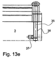
- FIG. 13 e shows in cross-section (A—A in FIG. 13 c ) how the handle 35 is lowered into the beam 3 .
- the hole 36 may be provided with a ball lock 37 in order that the handle 35 does not unsuitably slide out of the beam.
- FIG. 14 shows a further embodiment of the invention where the handle 35 on the hollow, oval tube 34 is disposed pivoting and sliding so that it may be lowered into the tube 34 itself.
- FIG. 14 a is a draft of the handle 35 when it is pulled out of the tube 34 and in a position for clamping the clamping rail 5 against the doctor beam 3 .
- a pivotable articulation 38 designed so that the handle 35 may be pivoted out into a position so that it is in parallel with the tube 34 in order that the handle 35 may be displaced into the tube 34 .
- FIG. 14 b shows the same situation as 14 a in another perspective toward the back side of the doctor beam 3 .
- FIG. 14 c shows the handle 35 lowered into the tube 34 .
- a ball lock 37 prevents that the handle 35 slides out of the tube 34 unintentionally.
Landscapes
- Engineering & Computer Science (AREA)
- Mechanical Engineering (AREA)
- Inking, Control Or Cleaning Of Printing Machines (AREA)
- Coating Apparatus (AREA)
- Rotary Presses (AREA)
- Paper (AREA)
- Actuator (AREA)
- Connection Of Plates (AREA)
- Clamps And Clips (AREA)
- Cyclones (AREA)
- Screen Printers (AREA)
Applications Claiming Priority (3)
| Application Number | Priority Date | Filing Date | Title |
|---|---|---|---|
| DK199900890 | 1999-06-22 | ||
| DKPA199900890 | 1999-06-22 | ||
| PCT/DK2000/000327 WO2000078548A1 (en) | 1999-06-22 | 2000-06-20 | Doctor blade system |
Publications (1)
| Publication Number | Publication Date |
|---|---|
| US6637330B1 true US6637330B1 (en) | 2003-10-28 |
Family
ID=8098692
Family Applications (1)
| Application Number | Title | Priority Date | Filing Date |
|---|---|---|---|
| US10/018,528 Expired - Lifetime US6637330B1 (en) | 1999-06-22 | 2000-06-20 | Doctor blade system |
Country Status (13)
| Country | Link |
|---|---|
| US (1) | US6637330B1 (de) |
| EP (1) | EP1196287B1 (de) |
| JP (1) | JP4921661B2 (de) |
| KR (1) | KR20020027349A (de) |
| AT (1) | ATE232464T1 (de) |
| AU (1) | AU762106B2 (de) |
| BR (1) | BR0011869A (de) |
| CA (1) | CA2375193C (de) |
| DE (1) | DE60001419T2 (de) |
| DK (1) | DK1196287T3 (de) |
| ES (1) | ES2192179T3 (de) |
| NO (1) | NO20016178D0 (de) |
| WO (1) | WO2000078548A1 (de) |
Cited By (15)
| Publication number | Priority date | Publication date | Assignee | Title |
|---|---|---|---|---|
| US6792855B2 (en) * | 2002-09-09 | 2004-09-21 | Uteco Holding S.P.A | Flexographic machine |
| WO2005080080A1 (de) * | 2004-02-11 | 2005-09-01 | Windmöller & Hölscher Kg | Druckwerk mit einem von einem trägerhalter gehaltenen rakelmesserträger |
| US20060027112A1 (en) * | 2002-11-28 | 2006-02-09 | Klaus Graeler | Ink reservoir doctor blade |
| US20060162592A1 (en) * | 2005-01-24 | 2006-07-27 | Roger Oberholzer | Gravure printing unit for printing a printing material web in a printing press |
| US20070144377A1 (en) * | 2004-08-21 | 2007-06-28 | Christoph Henninger | Doctor device |
| US20070209587A1 (en) * | 2003-11-19 | 2007-09-13 | Waldemar Kiener | Dosing Device And Apparatus For Applying Adhesives To At Least One Dosing Device, And Substrate Web |
| US20070266870A1 (en) * | 2003-12-30 | 2007-11-22 | Ake-Bosse International Ab | Doctor Blade System, Doctor Blade Clamping Device, Chambered Doctor Blade System, Printing Unit, Method for Clamping a Doctor Blade, and Method for Attaching a Clamping Portion or a Chambered Doctor Blade |
| EP2055481A1 (de) * | 2007-10-18 | 2009-05-06 | BOBST Group Italia SpA | Träger einer Rakelvorrichtung |
| US20110219968A1 (en) * | 2008-11-26 | 2011-09-15 | Christian Fogh-Hansen | Printing Unit with Curved Sealing Doctor Blade |
| CN105128508A (zh) * | 2014-05-26 | 2015-12-09 | 海德堡印刷机械股份公司 | 用于印刷机的刮刀装置 |
| US10046354B2 (en) | 2014-09-19 | 2018-08-14 | Chiba Machine Industry Corporation | Blade device, and printer and coating apparatus provided with said blade device |
| CN110154515A (zh) * | 2018-07-05 | 2019-08-23 | 上海鼎龙机械有限公司 | 印刷开槽模切机的刮刀快速拆换装置 |
| CN112055656A (zh) * | 2018-04-30 | 2020-12-08 | 鲍勃斯脱里昂公司 | 用于将刮墨刀紧固在刮墨刀腔上的装置及装备所述装置的刮墨刀腔 |
| CN115052749A (zh) * | 2020-01-22 | 2022-09-13 | 博斯特比勒费尔德有限公司 | 刮墨刀系统 |
| CN117839975A (zh) * | 2024-03-07 | 2024-04-09 | 新乡市新贝尔信息材料有限公司 | 一种涂布机用封边移栽装置及其使用方法 |
Families Citing this family (5)
| Publication number | Priority date | Publication date | Assignee | Title |
|---|---|---|---|---|
| KR100677677B1 (ko) | 2004-12-15 | 2007-02-02 | 김종백 | 독터 블레이드 홀더 |
| DE102007027384A1 (de) * | 2007-06-11 | 2009-03-12 | Windmöller & Hölscher Kg | Farbkammerrakel in einem Farbwerk einer Rotationsdruckmaschine sowie Verfahren zur Herstellung einer Farbkammerrakel |
| DE102010014030A1 (de) | 2010-04-06 | 2011-10-06 | Fischer & Krecke Gmbh | Rakelmesserhalterung für eine Druckmaschine |
| CN107614266B (zh) * | 2015-06-04 | 2019-06-21 | 丹麦得利速股份公司 | 组合刮墨刀腔 |
| CN115107359A (zh) * | 2021-03-17 | 2022-09-27 | 常州博斯特西太湖包装设备有限公司 | 快速更换刮墨刀片的刮刀架 |
Citations (34)
| Publication number | Priority date | Publication date | Assignee | Title |
|---|---|---|---|---|
| US2914788A (en) | 1957-02-22 | 1959-12-01 | D S T Pattern And Engineering | Doctor knives |
| US3085275A (en) | 1961-04-12 | 1963-04-16 | Thomas K Allison | Doctor blade and holder |
| US3309992A (en) | 1964-03-09 | 1967-03-21 | John C Motter Printing Press C | Blade adjsuting and clamping method and apparatus |
| GB1306654A (en) | 1970-09-02 | 1973-02-14 | Frankenthal Ag Albert | Doctor devices |
| US3730087A (en) | 1971-02-01 | 1973-05-01 | Continental Can Co | Doctor blade pressure/angle adjusting mechanism |
| US3866266A (en) | 1973-11-09 | 1975-02-18 | Lodding Engineering Corp | Self-adjusting doctor blades |
| US3878780A (en) * | 1973-01-02 | 1975-04-22 | Alsacienne Constr Meca | Resiliently supported air bladder for biasing squeegees |
| US3882817A (en) | 1974-01-11 | 1975-05-13 | Black Clawson Co | Doctor Blade Assembly |
| US3952650A (en) | 1973-09-21 | 1976-04-27 | Societe Alsacienne De Constructions Mecaniques De Mulhouse | Doctor-blade holder with cleaning means |
| US4040349A (en) * | 1974-12-19 | 1977-08-09 | Heidelberger Druckmaschinen Aktiengesellschaft | Ink fountain assembly for printing presses |
| US4078486A (en) | 1975-02-24 | 1978-03-14 | Fritz Buser Ag Maschinenfabrik | Doctoring device with blade cushioning mount |
| US4315425A (en) * | 1979-08-01 | 1982-02-16 | Haemmerle Ag | Clamping device for fastening a tool to a tool holder |
| US4561163A (en) | 1981-08-18 | 1985-12-31 | Cox Norman Victor | Fitting doctor blades |
| US4821672A (en) | 1987-06-22 | 1989-04-18 | Nick Bruno | Doctor blade assembly with rotary end seals and interchangeable heads |
| US4938131A (en) | 1987-05-15 | 1990-07-03 | Schiavi Cesare Costruzioni Meccaniche S.P.A. | Clamp device for the cylinder wiper blade in a rotogravure printing machine |
| US4940354A (en) | 1987-07-06 | 1990-07-10 | Jurg Holderegger | Mounting device for mounting a squeegee or inking blade in a printing press |
| EP0402589A2 (de) | 1989-06-10 | 1990-12-19 | J.M. Voith GmbH | Streicheinrichtung |
| DE9017689U1 (de) | 1990-07-24 | 1991-08-08 | Koenig & Bauer AG, 8700 Würzburg | Rakelmesserband |
| EP0611649A1 (de) | 1993-01-15 | 1994-08-24 | Paper Converting Machine Company | Vorrichtung und Verfahren zum Austauschen von Rabeln in Flexodruckmaschinen |
| US5341741A (en) | 1992-04-25 | 1994-08-30 | Koenig & Bauer Aktiengesellschaft | Doctor blade bar for a short inking system |
| US5406887A (en) | 1993-01-15 | 1995-04-18 | Paper Converting Machine Company | Apparatus and method for doctor blade replacement in a flexographic press |
| US5410961A (en) * | 1992-12-30 | 1995-05-02 | Fit Group, Inc. | Fountain assembly |
| DE4421350A1 (de) | 1994-06-17 | 1995-12-21 | Schenk Gmbh | Vorrichtung zur Befestigung eines Rakelblattes |
| US5483885A (en) | 1993-10-11 | 1996-01-16 | Jagenberg Papiertechnik Gmbh | Holder for a doctor rod |
| US5517918A (en) | 1994-07-29 | 1996-05-21 | Fischer & Krecke Gmbh & Co. | Doctor blade clamping assembly for a printing press |
| DE29611194U1 (de) | 1996-06-26 | 1996-09-05 | Voith Sulzer Papiermaschinen GmbH, 89522 Heidenheim | Befestigungseinrichtung |
| US5642664A (en) | 1994-11-10 | 1997-07-01 | Koenig & Bauer-Albert Aktiengesellschaft | Holding device for a chamber doctor blade |
| US5656083A (en) | 1994-07-19 | 1997-08-12 | Man Roland Druckmachinen Ag | Chamber doctor |
| DE29709301U1 (de) | 1997-05-27 | 1997-11-27 | Voith Sulzer Papiermaschinen GmbH, 89522 Heidenheim | Vorrichtung zum Befestigen von mindestens einem im wesentlichen ortsfest angeordneten dünnen, langgestreckten Funktionselement |
| US5740735A (en) * | 1995-10-31 | 1998-04-21 | Eastman Kodak Company | Apparatus for securing a surface |
| US5765480A (en) * | 1995-09-27 | 1998-06-16 | Komori Corporation | Wiping device of intaglio printing press |
| US5983798A (en) * | 1998-05-15 | 1999-11-16 | Tokyo Kikai Seisakusho, Ltd | Doctor blade apparatus |
| US6202252B1 (en) * | 1999-06-03 | 2001-03-20 | Valmet Ltd. | Doctoring apparatus |
| US6293195B1 (en) * | 1998-10-07 | 2001-09-25 | Alhsontech Sales Incorporated | Chambered flexographic ink units with quick-change, blade thickness compensating clamping mechanism |
Family Cites Families (3)
| Publication number | Priority date | Publication date | Assignee | Title |
|---|---|---|---|---|
| JPS61200234A (ja) * | 1985-02-27 | 1986-09-04 | ナショナル住宅産業株式会社 | 接合部材の支持構造 |
| JPH05261886A (ja) * | 1991-03-29 | 1993-10-12 | Dainippon Printing Co Ltd | クランプ装置 |
| JPH10272757A (ja) * | 1997-03-28 | 1998-10-13 | Dainippon Printing Co Ltd | ドクターホルダー |
-
2000
- 2000-06-20 ES ES00938578T patent/ES2192179T3/es not_active Expired - Lifetime
- 2000-06-20 CA CA002375193A patent/CA2375193C/en not_active Expired - Lifetime
- 2000-06-20 AU AU53904/00A patent/AU762106B2/en not_active Expired
- 2000-06-20 DE DE60001419T patent/DE60001419T2/de not_active Expired - Lifetime
- 2000-06-20 DK DK00938578T patent/DK1196287T3/da active
- 2000-06-20 BR BR0011869-9A patent/BR0011869A/pt not_active Application Discontinuation
- 2000-06-20 JP JP2001504577A patent/JP4921661B2/ja not_active Expired - Lifetime
- 2000-06-20 KR KR1020017016121A patent/KR20020027349A/ko not_active Withdrawn
- 2000-06-20 AT AT00938578T patent/ATE232464T1/de active
- 2000-06-20 WO PCT/DK2000/000327 patent/WO2000078548A1/en not_active Ceased
- 2000-06-20 EP EP00938578A patent/EP1196287B1/de not_active Expired - Lifetime
- 2000-06-20 US US10/018,528 patent/US6637330B1/en not_active Expired - Lifetime
-
2001
- 2001-12-18 NO NO20016178A patent/NO20016178D0/no not_active Application Discontinuation
Patent Citations (36)
| Publication number | Priority date | Publication date | Assignee | Title |
|---|---|---|---|---|
| US2914788A (en) | 1957-02-22 | 1959-12-01 | D S T Pattern And Engineering | Doctor knives |
| US3085275A (en) | 1961-04-12 | 1963-04-16 | Thomas K Allison | Doctor blade and holder |
| US3309992A (en) | 1964-03-09 | 1967-03-21 | John C Motter Printing Press C | Blade adjsuting and clamping method and apparatus |
| GB1306654A (en) | 1970-09-02 | 1973-02-14 | Frankenthal Ag Albert | Doctor devices |
| US3730087A (en) | 1971-02-01 | 1973-05-01 | Continental Can Co | Doctor blade pressure/angle adjusting mechanism |
| US3878780A (en) * | 1973-01-02 | 1975-04-22 | Alsacienne Constr Meca | Resiliently supported air bladder for biasing squeegees |
| US3952650A (en) | 1973-09-21 | 1976-04-27 | Societe Alsacienne De Constructions Mecaniques De Mulhouse | Doctor-blade holder with cleaning means |
| US3866266A (en) | 1973-11-09 | 1975-02-18 | Lodding Engineering Corp | Self-adjusting doctor blades |
| DE2500764A1 (de) | 1974-01-11 | 1975-07-17 | Black Clawson Co | Schaberklinge |
| US3882817A (en) | 1974-01-11 | 1975-05-13 | Black Clawson Co | Doctor Blade Assembly |
| US4040349A (en) * | 1974-12-19 | 1977-08-09 | Heidelberger Druckmaschinen Aktiengesellschaft | Ink fountain assembly for printing presses |
| US4078486A (en) | 1975-02-24 | 1978-03-14 | Fritz Buser Ag Maschinenfabrik | Doctoring device with blade cushioning mount |
| US4315425A (en) * | 1979-08-01 | 1982-02-16 | Haemmerle Ag | Clamping device for fastening a tool to a tool holder |
| US4561163A (en) | 1981-08-18 | 1985-12-31 | Cox Norman Victor | Fitting doctor blades |
| US4938131A (en) | 1987-05-15 | 1990-07-03 | Schiavi Cesare Costruzioni Meccaniche S.P.A. | Clamp device for the cylinder wiper blade in a rotogravure printing machine |
| US4821672A (en) | 1987-06-22 | 1989-04-18 | Nick Bruno | Doctor blade assembly with rotary end seals and interchangeable heads |
| US4940354A (en) | 1987-07-06 | 1990-07-10 | Jurg Holderegger | Mounting device for mounting a squeegee or inking blade in a printing press |
| US5081950A (en) | 1989-06-10 | 1992-01-21 | J. M. Voith Gmbh | Coating device |
| EP0402589A2 (de) | 1989-06-10 | 1990-12-19 | J.M. Voith GmbH | Streicheinrichtung |
| DE9017689U1 (de) | 1990-07-24 | 1991-08-08 | Koenig & Bauer AG, 8700 Würzburg | Rakelmesserband |
| US5341741A (en) | 1992-04-25 | 1994-08-30 | Koenig & Bauer Aktiengesellschaft | Doctor blade bar for a short inking system |
| US5410961A (en) * | 1992-12-30 | 1995-05-02 | Fit Group, Inc. | Fountain assembly |
| EP0611649A1 (de) | 1993-01-15 | 1994-08-24 | Paper Converting Machine Company | Vorrichtung und Verfahren zum Austauschen von Rabeln in Flexodruckmaschinen |
| US5406887A (en) | 1993-01-15 | 1995-04-18 | Paper Converting Machine Company | Apparatus and method for doctor blade replacement in a flexographic press |
| US5483885A (en) | 1993-10-11 | 1996-01-16 | Jagenberg Papiertechnik Gmbh | Holder for a doctor rod |
| DE4421350A1 (de) | 1994-06-17 | 1995-12-21 | Schenk Gmbh | Vorrichtung zur Befestigung eines Rakelblattes |
| US5656083A (en) | 1994-07-19 | 1997-08-12 | Man Roland Druckmachinen Ag | Chamber doctor |
| US5517918A (en) | 1994-07-29 | 1996-05-21 | Fischer & Krecke Gmbh & Co. | Doctor blade clamping assembly for a printing press |
| US5642664A (en) | 1994-11-10 | 1997-07-01 | Koenig & Bauer-Albert Aktiengesellschaft | Holding device for a chamber doctor blade |
| US5765480A (en) * | 1995-09-27 | 1998-06-16 | Komori Corporation | Wiping device of intaglio printing press |
| US5740735A (en) * | 1995-10-31 | 1998-04-21 | Eastman Kodak Company | Apparatus for securing a surface |
| DE29611194U1 (de) | 1996-06-26 | 1996-09-05 | Voith Sulzer Papiermaschinen GmbH, 89522 Heidenheim | Befestigungseinrichtung |
| DE29709301U1 (de) | 1997-05-27 | 1997-11-27 | Voith Sulzer Papiermaschinen GmbH, 89522 Heidenheim | Vorrichtung zum Befestigen von mindestens einem im wesentlichen ortsfest angeordneten dünnen, langgestreckten Funktionselement |
| US5983798A (en) * | 1998-05-15 | 1999-11-16 | Tokyo Kikai Seisakusho, Ltd | Doctor blade apparatus |
| US6293195B1 (en) * | 1998-10-07 | 2001-09-25 | Alhsontech Sales Incorporated | Chambered flexographic ink units with quick-change, blade thickness compensating clamping mechanism |
| US6202252B1 (en) * | 1999-06-03 | 2001-03-20 | Valmet Ltd. | Doctoring apparatus |
Cited By (24)
| Publication number | Priority date | Publication date | Assignee | Title |
|---|---|---|---|---|
| US6792855B2 (en) * | 2002-09-09 | 2004-09-21 | Uteco Holding S.P.A | Flexographic machine |
| US20060027112A1 (en) * | 2002-11-28 | 2006-02-09 | Klaus Graeler | Ink reservoir doctor blade |
| US7287471B2 (en) * | 2002-11-28 | 2007-10-30 | Windmoeller & Hoelscher Kg | Ink reservoir doctor blade |
| US20070209587A1 (en) * | 2003-11-19 | 2007-09-13 | Waldemar Kiener | Dosing Device And Apparatus For Applying Adhesives To At Least One Dosing Device, And Substrate Web |
| US20070266870A1 (en) * | 2003-12-30 | 2007-11-22 | Ake-Bosse International Ab | Doctor Blade System, Doctor Blade Clamping Device, Chambered Doctor Blade System, Printing Unit, Method for Clamping a Doctor Blade, and Method for Attaching a Clamping Portion or a Chambered Doctor Blade |
| US7987783B2 (en) * | 2003-12-30 | 2011-08-02 | Ake-Boose International Ab | Doctor blade system, doctor blade clamping device, chambered doctor blade system, printing unit, method for clamping a doctor blade, and method for attaching a clamping portion of a chambered doctor blade |
| WO2005080080A1 (de) * | 2004-02-11 | 2005-09-01 | Windmöller & Hölscher Kg | Druckwerk mit einem von einem trägerhalter gehaltenen rakelmesserträger |
| US20070144377A1 (en) * | 2004-08-21 | 2007-06-28 | Christoph Henninger | Doctor device |
| US8082875B2 (en) * | 2004-08-21 | 2011-12-27 | Voith Patent Gmbh | Doctor device |
| US20060162592A1 (en) * | 2005-01-24 | 2006-07-27 | Roger Oberholzer | Gravure printing unit for printing a printing material web in a printing press |
| EP2055481A1 (de) * | 2007-10-18 | 2009-05-06 | BOBST Group Italia SpA | Träger einer Rakelvorrichtung |
| US20110219968A1 (en) * | 2008-11-26 | 2011-09-15 | Christian Fogh-Hansen | Printing Unit with Curved Sealing Doctor Blade |
| CN105128508A (zh) * | 2014-05-26 | 2015-12-09 | 海德堡印刷机械股份公司 | 用于印刷机的刮刀装置 |
| CN105128508B (zh) * | 2014-05-26 | 2018-10-09 | 海德堡印刷机械股份公司 | 用于印刷机的刮刀装置 |
| US10046354B2 (en) | 2014-09-19 | 2018-08-14 | Chiba Machine Industry Corporation | Blade device, and printer and coating apparatus provided with said blade device |
| CN112055656A (zh) * | 2018-04-30 | 2020-12-08 | 鲍勃斯脱里昂公司 | 用于将刮墨刀紧固在刮墨刀腔上的装置及装备所述装置的刮墨刀腔 |
| CN112055656B (zh) * | 2018-04-30 | 2022-01-14 | 鲍勃斯脱里昂公司 | 用于将刮墨刀紧固在刮墨刀腔上的装置及装备所述装置的刮墨刀腔 |
| US11420436B2 (en) | 2018-04-30 | 2022-08-23 | Bobst Lyon | Device for attaching a doctor blade on a doctor blade chamber and doctor blade chamber thus equipped |
| CN110154515A (zh) * | 2018-07-05 | 2019-08-23 | 上海鼎龙机械有限公司 | 印刷开槽模切机的刮刀快速拆换装置 |
| CN115052749A (zh) * | 2020-01-22 | 2022-09-13 | 博斯特比勒费尔德有限公司 | 刮墨刀系统 |
| CN115052749B (zh) * | 2020-01-22 | 2023-09-22 | 博斯特比勒费尔德有限公司 | 刮墨刀系统 |
| US11820123B2 (en) | 2020-01-22 | 2023-11-21 | Bobst Bielefeld Gmbh | Doctor blade system |
| CN117839975A (zh) * | 2024-03-07 | 2024-04-09 | 新乡市新贝尔信息材料有限公司 | 一种涂布机用封边移栽装置及其使用方法 |
| CN117839975B (zh) * | 2024-03-07 | 2024-05-28 | 新乡市新贝尔信息材料有限公司 | 一种涂布机用封边移栽装置及其使用方法 |
Also Published As
| Publication number | Publication date |
|---|---|
| EP1196287A1 (de) | 2002-04-17 |
| DE60001419T2 (de) | 2003-11-27 |
| NO20016178L (no) | 2001-12-18 |
| ATE232464T1 (de) | 2003-02-15 |
| KR20020027349A (ko) | 2002-04-13 |
| NO20016178D0 (no) | 2001-12-18 |
| ES2192179T3 (es) | 2003-10-01 |
| CA2375193C (en) | 2008-09-23 |
| EP1196287B1 (de) | 2003-02-12 |
| BR0011869A (pt) | 2002-03-05 |
| AU5390400A (en) | 2001-01-09 |
| DE60001419D1 (de) | 2003-03-20 |
| DK1196287T3 (da) | 2003-06-10 |
| CA2375193A1 (en) | 2000-12-28 |
| AU762106B2 (en) | 2003-06-19 |
| WO2000078548A1 (en) | 2000-12-28 |
| JP4921661B2 (ja) | 2012-04-25 |
| JP2003502192A (ja) | 2003-01-21 |
Similar Documents
| Publication | Publication Date | Title |
|---|---|---|
| EP1196287B1 (de) | Kammerrakelsystem | |
| US4461211A (en) | Flush inking mechanism for a rotary printing press | |
| JP2763347B2 (ja) | 印刷機のドクタ式インキ装置 | |
| CA2206816C (en) | Ink unit for printing press and method | |
| CN1325175C (zh) | 刮刀定量系统 | |
| US5983797A (en) | End seal engaging bearer of anilox roller assembly | |
| US6202252B1 (en) | Doctoring apparatus | |
| US5345867A (en) | Doctor blade bar assembly | |
| GB2042937A (en) | Doctor bar | |
| US6293195B1 (en) | Chambered flexographic ink units with quick-change, blade thickness compensating clamping mechanism | |
| US5297490A (en) | Apparatus for placement of a doctor blade bar against an ink-dispensing roller | |
| DK2649236T3 (en) | Rachel Holder | |
| US5341741A (en) | Doctor blade bar for a short inking system | |
| FI108654B (fi) | Paperikoneen kaapimen kuormitusjärjestely | |
| US4141112A (en) | Doctors for paper-making machines | |
| US6779452B2 (en) | Devices for pressing a blanket on a cylinder | |
| US4893562A (en) | Bearer wiper assembly | |
| US5345866A (en) | Doctor blade bar assembly | |
| US5461979A (en) | Multiple blade ink knife | |
| EP1699634B1 (de) | Rakelsystem und verfahren zum festklemmen einer rakel | |
| US6272988B1 (en) | Device for cleaning bearer surfaces on rotating cylinders | |
| US4938131A (en) | Clamp device for the cylinder wiper blade in a rotogravure printing machine | |
| US2847935A (en) | Washup attachment for printing presses and the like | |
| US6286426B1 (en) | Doctor blades | |
| SU1729572A1 (ru) | Устройство дл очистки поверхности валка |
Legal Events
| Date | Code | Title | Description |
|---|---|---|---|
| AS | Assignment |
Owner name: TRESU PRODUCTION A/S, DENMARK Free format text: ASSIGNMENT OF ASSIGNORS INTEREST;ASSIGNORS:NORDBY, KLAUS;LARSEN, JAN KJAER;GYDESEN, ERIK;AND OTHERS;REEL/FRAME:012647/0383 Effective date: 20020104 |
|
| STCF | Information on status: patent grant |
Free format text: PATENTED CASE |
|
| FPAY | Fee payment |
Year of fee payment: 4 |
|
| FEPP | Fee payment procedure |
Free format text: PAT HOLDER CLAIMS SMALL ENTITY STATUS, ENTITY STATUS SET TO SMALL (ORIGINAL EVENT CODE: LTOS); ENTITY STATUS OF PATENT OWNER: SMALL ENTITY |
|
| FPAY | Fee payment |
Year of fee payment: 8 |
|
| FPAY | Fee payment |
Year of fee payment: 12 |