US6648091B2 - Hydraulic circuit for traveling - Google Patents
Hydraulic circuit for traveling Download PDFInfo
- Publication number
- US6648091B2 US6648091B2 US09/968,205 US96820501A US6648091B2 US 6648091 B2 US6648091 B2 US 6648091B2 US 96820501 A US96820501 A US 96820501A US 6648091 B2 US6648091 B2 US 6648091B2
- Authority
- US
- United States
- Prior art keywords
- hydraulic
- braking force
- detection controller
- rotational
- hydraulic motors
- Prior art date
- Legal status (The legal status is an assumption and is not a legal conclusion. Google has not performed a legal analysis and makes no representation as to the accuracy of the status listed.)
- Expired - Fee Related
Links
Images


Classifications
-
- F—MECHANICAL ENGINEERING; LIGHTING; HEATING; WEAPONS; BLASTING
- F16—ENGINEERING ELEMENTS AND UNITS; GENERAL MEASURES FOR PRODUCING AND MAINTAINING EFFECTIVE FUNCTIONING OF MACHINES OR INSTALLATIONS; THERMAL INSULATION IN GENERAL
- F16H—GEARING
- F16H61/00—Control functions within control units of change-speed- or reversing-gearings for conveying rotary motion ; Control of exclusively fluid gearing, friction gearing, gearings with endless flexible members or other particular types of gearing
- F16H61/38—Control of exclusively fluid gearing
- F16H61/40—Control of exclusively fluid gearing hydrostatic
- F16H61/4157—Control of braking, e.g. preventing pump over-speeding when motor acts as a pump
-
- B—PERFORMING OPERATIONS; TRANSPORTING
- B60—VEHICLES IN GENERAL
- B60T—VEHICLE BRAKE CONTROL SYSTEMS OR PARTS THEREOF; BRAKE CONTROL SYSTEMS OR PARTS THEREOF, IN GENERAL; ARRANGEMENT OF BRAKING ELEMENTS ON VEHICLES IN GENERAL; PORTABLE DEVICES FOR PREVENTING UNWANTED MOVEMENT OF VEHICLES; VEHICLE MODIFICATIONS TO FACILITATE COOLING OF BRAKES
- B60T13/00—Transmitting braking action from initiating means to ultimate brake actuator with power assistance or drive; Brake systems incorporating such transmitting means, e.g. air-pressure brake systems
- B60T13/10—Transmitting braking action from initiating means to ultimate brake actuator with power assistance or drive; Brake systems incorporating such transmitting means, e.g. air-pressure brake systems with fluid assistance, drive, or release
- B60T13/66—Electrical control in fluid-pressure brake systems
- B60T13/68—Electrical control in fluid-pressure brake systems by electrically-controlled valves
- B60T13/686—Electrical control in fluid-pressure brake systems by electrically-controlled valves in hydraulic systems or parts thereof
-
- B—PERFORMING OPERATIONS; TRANSPORTING
- B60—VEHICLES IN GENERAL
- B60T—VEHICLE BRAKE CONTROL SYSTEMS OR PARTS THEREOF; BRAKE CONTROL SYSTEMS OR PARTS THEREOF, IN GENERAL; ARRANGEMENT OF BRAKING ELEMENTS ON VEHICLES IN GENERAL; PORTABLE DEVICES FOR PREVENTING UNWANTED MOVEMENT OF VEHICLES; VEHICLE MODIFICATIONS TO FACILITATE COOLING OF BRAKES
- B60T8/00—Arrangements for adjusting wheel-braking force to meet varying vehicular or ground-surface conditions, e.g. limiting or varying distribution of braking force
- B60T8/32—Arrangements for adjusting wheel-braking force to meet varying vehicular or ground-surface conditions, e.g. limiting or varying distribution of braking force responsive to a speed condition, e.g. acceleration or deceleration
- B60T8/34—Arrangements for adjusting wheel-braking force to meet varying vehicular or ground-surface conditions, e.g. limiting or varying distribution of braking force responsive to a speed condition, e.g. acceleration or deceleration having a fluid pressure regulator responsive to a speed condition
- B60T8/48—Arrangements for adjusting wheel-braking force to meet varying vehicular or ground-surface conditions, e.g. limiting or varying distribution of braking force responsive to a speed condition, e.g. acceleration or deceleration having a fluid pressure regulator responsive to a speed condition connecting the brake actuator to an alternative or additional source of fluid pressure, e.g. traction control systems
- B60T8/4809—Traction control, stability control, using both the wheel brakes and other automatic braking systems
-
- B—PERFORMING OPERATIONS; TRANSPORTING
- B60—VEHICLES IN GENERAL
- B60W—CONJOINT CONTROL OF VEHICLE SUB-UNITS OF DIFFERENT TYPE OR DIFFERENT FUNCTION; CONTROL SYSTEMS SPECIALLY ADAPTED FOR HYBRID VEHICLES; ROAD VEHICLE DRIVE CONTROL SYSTEMS FOR PURPOSES NOT RELATED TO THE CONTROL OF A PARTICULAR SUB-UNIT
- B60W10/00—Conjoint control of vehicle sub-units of different type or different function
- B60W10/18—Conjoint control of vehicle sub-units of different type or different function including control of braking systems
- B60W10/184—Conjoint control of vehicle sub-units of different type or different function including control of braking systems with wheel brakes
-
- F—MECHANICAL ENGINEERING; LIGHTING; HEATING; WEAPONS; BLASTING
- F16—ENGINEERING ELEMENTS AND UNITS; GENERAL MEASURES FOR PRODUCING AND MAINTAINING EFFECTIVE FUNCTIONING OF MACHINES OR INSTALLATIONS; THERMAL INSULATION IN GENERAL
- F16H—GEARING
- F16H61/00—Control functions within control units of change-speed- or reversing-gearings for conveying rotary motion ; Control of exclusively fluid gearing, friction gearing, gearings with endless flexible members or other particular types of gearing
- F16H61/38—Control of exclusively fluid gearing
- F16H61/40—Control of exclusively fluid gearing hydrostatic
- F16H61/42—Control of exclusively fluid gearing hydrostatic involving adjustment of a pump or motor with adjustable output or capacity
- F16H61/421—Motor capacity control by electro-hydraulic control means, e.g. using solenoid valves
-
- B—PERFORMING OPERATIONS; TRANSPORTING
- B60—VEHICLES IN GENERAL
- B60K—ARRANGEMENT OR MOUNTING OF PROPULSION UNITS OR OF TRANSMISSIONS IN VEHICLES; ARRANGEMENT OR MOUNTING OF PLURAL DIVERSE PRIME-MOVERS IN VEHICLES; AUXILIARY DRIVES FOR VEHICLES; INSTRUMENTATION OR DASHBOARDS FOR VEHICLES; ARRANGEMENTS IN CONNECTION WITH COOLING, AIR INTAKE, GAS EXHAUST OR FUEL SUPPLY OF PROPULSION UNITS IN VEHICLES
- B60K17/00—Arrangement or mounting of transmissions in vehicles
- B60K17/04—Arrangement or mounting of transmissions in vehicles characterised by arrangement, location or kind of gearing
- B60K17/10—Arrangement or mounting of transmissions in vehicles characterised by arrangement, location or kind of gearing of fluid gearing
-
- B—PERFORMING OPERATIONS; TRANSPORTING
- B60—VEHICLES IN GENERAL
- B60K—ARRANGEMENT OR MOUNTING OF PROPULSION UNITS OR OF TRANSMISSIONS IN VEHICLES; ARRANGEMENT OR MOUNTING OF PLURAL DIVERSE PRIME-MOVERS IN VEHICLES; AUXILIARY DRIVES FOR VEHICLES; INSTRUMENTATION OR DASHBOARDS FOR VEHICLES; ARRANGEMENTS IN CONNECTION WITH COOLING, AIR INTAKE, GAS EXHAUST OR FUEL SUPPLY OF PROPULSION UNITS IN VEHICLES
- B60K28/00—Safety devices for propulsion-unit control, specially adapted for, or arranged in, vehicles, e.g. preventing fuel supply or ignition in the event of potentially dangerous conditions
- B60K28/10—Safety devices for propulsion-unit control, specially adapted for, or arranged in, vehicles, e.g. preventing fuel supply or ignition in the event of potentially dangerous conditions responsive to conditions relating to the vehicle
- B60K28/16—Safety devices for propulsion-unit control, specially adapted for, or arranged in, vehicles, e.g. preventing fuel supply or ignition in the event of potentially dangerous conditions responsive to conditions relating to the vehicle responsive to, or preventing, spinning or skidding of wheels
-
- B—PERFORMING OPERATIONS; TRANSPORTING
- B60—VEHICLES IN GENERAL
- B60T—VEHICLE BRAKE CONTROL SYSTEMS OR PARTS THEREOF; BRAKE CONTROL SYSTEMS OR PARTS THEREOF, IN GENERAL; ARRANGEMENT OF BRAKING ELEMENTS ON VEHICLES IN GENERAL; PORTABLE DEVICES FOR PREVENTING UNWANTED MOVEMENT OF VEHICLES; VEHICLE MODIFICATIONS TO FACILITATE COOLING OF BRAKES
- B60T2270/00—Further aspects of brake control systems not otherwise provided for
- B60T2270/20—ASR control systems
- B60T2270/203—ASR control systems hydraulic system components
-
- F—MECHANICAL ENGINEERING; LIGHTING; HEATING; WEAPONS; BLASTING
- F16—ENGINEERING ELEMENTS AND UNITS; GENERAL MEASURES FOR PRODUCING AND MAINTAINING EFFECTIVE FUNCTIONING OF MACHINES OR INSTALLATIONS; THERMAL INSULATION IN GENERAL
- F16H—GEARING
- F16H59/00—Control inputs to control units of change-speed- or reversing-gearings for conveying rotary motion
- F16H59/68—Inputs being a function of gearing status
- F16H2059/6838—Sensing gearing status of hydrostatic transmissions
- F16H2059/6876—Sensing gearing status of hydrostatic transmissions the motor speed
-
- F—MECHANICAL ENGINEERING; LIGHTING; HEATING; WEAPONS; BLASTING
- F16—ENGINEERING ELEMENTS AND UNITS; GENERAL MEASURES FOR PRODUCING AND MAINTAINING EFFECTIVE FUNCTIONING OF MACHINES OR INSTALLATIONS; THERMAL INSULATION IN GENERAL
- F16H—GEARING
- F16H63/00—Control outputs from the control unit to change-speed- or reversing-gearings for conveying rotary motion or to other devices than the final output mechanism
- F16H63/02—Final output mechanisms therefor; Actuating means for the final output mechanisms
- F16H63/30—Constructional features of the final output mechanisms
- F16H63/3023—Constructional features of the final output mechanisms the final output mechanisms comprising elements moved by fluid pressure
- F16H63/3026—Constructional features of the final output mechanisms the final output mechanisms comprising elements moved by fluid pressure comprising friction clutches or brakes
- F16H2063/3033—Constructional features of the final output mechanisms the final output mechanisms comprising elements moved by fluid pressure comprising friction clutches or brakes the brake is actuated by springs and released by a fluid pressure
-
- F—MECHANICAL ENGINEERING; LIGHTING; HEATING; WEAPONS; BLASTING
- F16—ENGINEERING ELEMENTS AND UNITS; GENERAL MEASURES FOR PRODUCING AND MAINTAINING EFFECTIVE FUNCTIONING OF MACHINES OR INSTALLATIONS; THERMAL INSULATION IN GENERAL
- F16H—GEARING
- F16H61/00—Control functions within control units of change-speed- or reversing-gearings for conveying rotary motion ; Control of exclusively fluid gearing, friction gearing, gearings with endless flexible members or other particular types of gearing
- F16H61/38—Control of exclusively fluid gearing
- F16H61/40—Control of exclusively fluid gearing hydrostatic
- F16H61/44—Control of exclusively fluid gearing hydrostatic with more than one pump or motor in operation
Definitions
- the present invention relates to a hydraulic circuit for traveling in which two hydraulic motors for driving the traveling wheels can be rotated by employing one hydraulic pump.
- the opening-closing valve 19 by switching the opening-closing valve 19 from an open to closed state, the flow passing areas of the bifurcate portions 16 a, 16 b are controlled by the flow dividing valve 17 in accordance with the loads applied on the hydraulic motors 14 , 15 , so that the high pressure fluid from the hydraulic pump 11 is supplied in equal amount to the hydraulic motors 14 , 15 to continue the traveling.
- the flow dividing valve 17 is used to supply an equal amount of high pressure fluid to the hydraulic motors 14 , 15 .
- this flow dividing valve 17 produces a great pressure loss when the fluid passes through it, the hydraulic motors 14 , 15 have the lower pressure applied.
- the rotational torque traction force
- the invention is characterized by having the following arrangement.
- a preferred embodiment of the hydraulic circuit for traveling includes a hydraulic pump, two hydraulic motors for driving and rotating the traveling wheels and a pumping passage for supplying a high pressure fluid discharged from the hydraulic pump to the two hydraulic motors.
- the pumping passage includes one end connected to the hydraulic pump and is bifurcated such that other ends are connected to the hydraulic motors.
- Two rotation detectors detect the rotational speeds of the hydraulic motors, respectively.
- a detection controller detects whether or not any traveling wheel is skidding by comparing the rotational speeds detected by the rotation detectors.
- Two braking force applying members apply a braking force only to the hydraulic motor of the skidding traveling wheel on the basis of the result of detection from the detection controller.
- the braking force applying members are installed in each of the hydraulic motors.
- a traction control system for a traveling vehicle of a preferred embodiment includes at least two traveling wheels driven by a single hydraulic pump through respective hydraulic motors.
- the traction control system includes rotation detectors for respectively detecting rotation speeds of the traveling wheels, a computer, connected to the rotation detectors, for comparing the rotational speeds of the traveling wheels and computer-controlled brake units respectively provided to the traveling wheels, and independently controlled by the computer.
- a preferred brake system for a traveling vehicle having at least two traveling wheels driven by a single hydraulic pump through respective hydraulic motors includes a parking brake for applying braking force to both of the traveling wheels when the hydraulic pump is not driven or the hydraulic pump does not provide sufficient hydraulic pressure to the hydraulic motors and an auxiliary brake for applying braking force to only one of the traveling wheels independently of the parking brake.
- the high pressure fluid from the hydraulic pump is substantially supplied to one hydraulic motor, so that one hydraulic motor is rotating (skidding) at high speed and the other hydraulic motor hardly rotates.
- the rotational speeds of the hydraulic motors are detected by the rotation detector, respectively, and the results of detection are output to detection controller.
- the detection controller detects that one traveling wheel is skidding by comparing the results of detection.
- the detection controller activates one braking force applying member to apply a braking force to one hydraulic motor alone, and balance the load of one hydraulic motor with that of the other hydraulic motor. Thereby, the high pressure fluid is also supplied to the other hydraulic motor, which is then rotated to continue the traveling. And if the other hydraulic motor is rotated, all the fluid discharge from the hydraulic pump is not supplied to one hydraulic motor, whereby it is possible to prevent one hydraulic motor from being damaged due to over speed.
- the braking force can be applied to the hydraulic motors in a simple constitution.
- the negative brakes installed in the hydraulic motors can be directly employed to apply the braking force to the traveling wheels that are skidding.
- the braking force applied to the hydraulic motors can be easily controlled.
- FIG. 1 is a circuit diagram showing one embodiment of the present invention.
- FIG. 2 is a cross-sectional view around a negative brake.
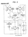
- FIG. 3 is a circuit diagram showing one example of the related hydraulic circuit for traveling.
- reference numeral 21 denotes a variable displacement hydraulic pump, and this hydraulic pump 21 , when driven by an engine 22 , discharges a high pressure fluid through a flow inlet-outlet opening 21 a or 21 b.
- Reference numerals 23 , 24 denote two variable displacement hydraulic motors having the flow inlet-output openings 23 a, 23 b and the flow inlet-outlet openings 24 a, 24 b, respectively.
- a pumping passage 25 includes one end connected to the flow inlet-outlet opening 21 a of the hydraulic pump 21 , and is bifurcated halfway to provide other ends respectively connected to the flow inlet-outlet openings 23 a, 24 a of these hydraulic motors 23 , 24 .
- a pumping passage 26 includes one end connected to the flow inlet-outlet opening 21 b of the hydraulic pump 21 and is bifurcated halfway to provide other ends respectively connected to the flow inlet-outlet openings 23 b, 24 b of these hydraulic motors 23 , 24 .
- a high pressure fluid discharged from the hydraulic pump 21 is supplied through the pumping passage 25 or 26 to two hydraulic motors 23 , 24 , and a low pressure fluid flowing from the hydraulic motors 23 , 24 is returned through the remaining pumping passage 25 or 26 to the hydraulic pump 21 , so that the hydraulic motors 23 , 24 are driven to rotate the rotational shafts 23 c, 24 c in a forward or backward direction.
- the traveling wheels 27 , 28 for the civil construction machine or the like are connected to these rotational shafts 23 c, 24 c, respectively, these traveling wheels 27 , 28 are rotated together with the rotational shafts 23 c, 24 c, whereby the civil construction machine can travel.
- the hydraulic motors 23 , 24 employs a swash plate type hydraulic motor having a swash plate 31 capable of changing the angle of inclination thereof, as shown in FIG. 2 .
- one or more ring-like stationary counterpart plates 33 are connected axially movably on a stationary portion of the hydraulic motor 23 , 24 (the inner peripheries of the stationary casing 32 of the hydraulic motor 23 , 24 in this embodiment) by spline connection or mating at two positions.
- one or more ring-like rotational friction plates 35 are connected axially movably on the rotational portion of the hydraulic motor 23 , 24 (the outer peripheries of a cylinder block 34 of the hydraulic motor 23 , 24 in this embodiment) by spline connection or mating at two positions to be rotatable integrally with the cylinder block 34 .
- the stationary counterpart plate 33 and the rotational friction plate 35 are disposed alternately in the axial direction.
- Reference numeral 37 denotes a plurality of springs disposed on one side of the rotational friction plate 35 , these springs 37 bring the stationary counterpart plate 33 and the rotational friction plate 35 into frictional contact with each other via a substantially cylindrical braking piston 38 , providing a braking force to the rotational portion of the hydraulic motors 23 , 24 .
- Reference numeral 39 denotes a cylinder chamber formed between the stationary casing 32 and the braking piston 38 , in which if a high pressure fluid is supplied into the cylinder chamber 39 , the braking piston 38 is moved to one side against the springs 37 . Thereby, the braking piston 38 is separated from the stationary counterpart plate 33 and the rotational friction plate 35 to disengage them from the frictional contact, so as to release the braking for the rotational portion.
- the braking piston 38 is urged by the springs 37 and brings the stationary counterpart plate 33 and the rotational friction plate 35 into frictional contact with each other.
- the stationary counterpart plate 33 , the rotational friction plate 35 , the springs 37 and the braking piston 38 constitute a pair of negative brakes 40 , 41 to provide a braking force to the hydraulic motors 23 , 24 .
- Reference numeral 45 denotes a hydraulic pump which is driven with the hydraulic pump 21 by the engine 22 to discharge a high pressure fluid, a suction opening 45 a of this hydraulic pump 45 being connected through a suction passage 47 to a tank 46 .
- a discharge opening 45 b of the hydraulic pump 45 is connected to one end of a supply passage 48 , which is bifurcated halfway, the other ends of the supply passage 48 being connected to the cylinder chambers 39 of the negative brakes 40 , 41 , respectively.
- a directional control valve 49 is interposed in the supply passage 48 between the hydraulic pump 45 and the branch portion.
- this directional control valve 49 is switched to an oblique flow position, a high pressure fluid discharged from the hydraulic pump 45 is supplied to the cylinder chambers 39 of the negative brakes 40 , 41 .
- the directional control valve 49 is switched to a parallel flow position, a fluid from the cylinder chambers 39 of the negative brakes 40 , 41 is exhausted into the tank 46 .
- Reference numeral 51 denotes a make-up feed passage having one end connected to the supply passage 48 between the hydraulic pump 45 and the directional control valve 49 , bifurcated halfway, with the other ends connected to the pumping passages 25 , 26 , respectively.
- the bifurcate portions 51 a, 51 b of this make-up feed passage 51 are provided with the check valves 52 , 53 for permitting only a flow of fluid to the pumping passages 25 , 26 , respectively.
- a high pressure fluid discharged from the hydraulic pump 45 is refilled through the make-up feed passage 51 to the pumping passage 25 or 26 on the lower pressure side, when the check valve 52 or 53 is opened.
- Reference numerals 54 , 55 denotes a relief valve provided in the make-up feed passage 51 , these relief valves 54 , 55 being arranged in parallel to the check valves 52 , 53 , respectively.
- Reference numeral 56 denotes a relief passage having one end connected to the supply passage 48 between the hydraulic pump 45 and the directional control valve 49 , with the other end being connected to the tank 46 , a relief valve 57 being interposed halfway in this relief passage 56 .
- Reference numeral 59 denotes a flushing valve, which is connected to the other ends of the first and second passages 60 , 61 having one ends connected to the pumping passages 25 , 26 , respectively. If this flushing valve 59 is turn open by a pilot pressure from the first or second passage 60 or 61 on the high pressure side, a fluid in the first or second passage 60 , 61 on the low pressure side is flowed out through a flow-out passage 62 to a drain chamber of the hydraulic pump 21 , refreshing the fluid within the pumping passages 25 , 26 continuously and cooling the hydraulic pump 21 .
- Reference numeral 63 denotes a low pressure relief valve interposed halfway in the flow-out passage 62 .
- Reference numerals 66 , 67 denote the rotation detectors such as rotary encoder for detecting the rotational speed of the hydraulic motors 23 , 24 . These two rotation detectors 66 , 67 detect the rotational speed of the traveling wheels 27 , 28 or the rotational shafts 23 c, 24 c, thereby detecting the rotational speed of the hydraulic motors 23 , 24 , and output its detection result to detection controller 68 connected to the rotation detectors 66 , 67 and composed of a CPU. The detection controller 68 compares the rotational speeds of the hydraulic motors 23 , 24 detected by the rotation detectors 66 , 67 , and determines that either the traveling wheel 27 or 28 is skidding if the difference is greater than or equal to a predetermined value.
- the detection controller 68 compares the rotational speeds of the hydraulic motors 23 , 24 detected by the rotation detectors 66 , 67 , and determines that either the traveling wheel 27 or 28 is skidding if the difference is greater than or equal to a predetermined
- Reference numeral 71 denotes a cylindrical piston disposed in a superposed state radially inside the braking piston 38 constituting the negative brakes 40 , 41 .
- This cylindrical piston 71 is moved to the other side and brings the stationary counterpart plate 33 and the rotational friction plate 35 into frictional contact with each other to provide a braking force to the hydraulic motors 23 , 24 , if a high pressure fluid is supplied to a cylinder chamber 72 formed between the stationary casing 32 and the piston 71 .
- Reference numeral 74 denotes a fluid passage having one end connected to the supply passage 48 between the hydraulic pump 45 and the directional control valve 49 , bifurcated halfway, with the other ends being connected to the cylinder chambers 72 of the negative brakes 40 , 41 .
- the control valves (the pressure reducing valves 75 , 76 in this embodiment) for controlling the high pressure fluid to be led to the piston 71 in accordance with a control signal from the detection controller 68 are interposed.
- the detection controller 68 controls the pressure reducing valve 75 or 76 by outputting a control signal to the coil of corresponding pressure reducing valve 75 or 76 if detecting that either of the traveling wheels 27 , 28 is skidding. Thereby, a high pressure fluid is supplied from the hydraulic pump 45 to the cylinder chamber 72 of the hydraulic motor 23 or 24 to provide a braking force to the hydraulic motor 23 or 24 .
- the piston 71 and the pressure reducing valves 75 , 76 are installed in the hydraulic motors 23 , 24 , respectively, and constitute two braking force applying members 77 , 78 for applying a braking force only to the skidding hydraulic motors 23 , 24 of the traveling wheel 27 , 28 in accordance with the detection result of the detection controller 68 . If each braking force applying members 77 , 78 is constituted by the piston 71 and the pressure reducing valves 75 , 76 , it is possible to apply a braking force to the hydraulic motors 23 , 24 in a simple construction.
- the detection controller 68 is connected to a foot brake 80 of the civil construction machine, more particularly, a detection sensor for detecting the amount of treading the foot brake 80 , the amount of treading the foot brake 80 detected by the detection sensor 81 is input into the detection controller 68 , and a control signal from the detection controller 68 in accordance with the amount of treading the foot brake 80 is output to the coil (particularly a proportional coil) of the pressure reducing valve 75 or 76 , increasing or decreasing the secondary pressure of the pressure reducing valve 75 or 76 .
- the pressure of the fluid supplied to the cylinder chamber 72 of the hydraulic motor 23 or 24 in other words, a braking force provided from the negative brakes 40 , 41 to the hydraulic motors 23 , 24 can be easily controlled in a range of appropriate values.
- the rotational speed of the inward traveling wheel is slower than the rotational speed of the outward traveling wheel, thereby bringing about the danger that the detection controller 68 detects the outward traveling wheel to be skidding even if the traveling wheel is not actually skidding.
- the detection controller 68 is connected to the steering system 83 , for example, the detection sensor 84 for detecting the steering angle (motion amount) of a steering shaft, to input the steering angle of the steering system 83 detected by the detection sensor 84 into the detection controller 68 .
- the hydraulic pumps 21 , 45 are rotated in the forward direction, and a high pressure fluid is discharged from the hydraulic pumps 21 , 45 to the pumping passage 25 and the supply passage 48 , the high pressure fluid discharged from the hydraulic pump 21 is flowed into the hydraulic motors 23 , 24 simultaneously.
- the rotational shafts 23 c, 24 c of the hydraulic motors 23 , 24 are rotated together with the traveling wheels 27 , 28 , so that the civil construction machine moves in forward direction.
- the high pressure fluid discharged from the fluid pump 45 pushes open the check valve 53 to be always refilled to the pumping passage 26 on the low pressure side, so that the fluid within the circuit is replaced successively, thereby preventing the deterioration.
- the fluid is refilled to the pumping passage 26 , the amount of fluid within the circuit increases to raise the circuit pressure, but at this time, excess fluid is exhausted through the flushing valve 59 and the relief valve 63 to a drain chamber of the hydraulic pump 21 . Thereby, the circuit pressure is prevented from rising. And the hydraulic pump 21 is cooled.
- the rotational speeds of the traveling wheels 27 , 28 detected by the rotation detectors 66 , 67 are output to the detection controller 68 .
- the detection controller 68 determines that any traveling wheels 27 , 28 are not skidding.
- the detection controller 68 controls the pressure reducing valves 75 , 76 so that the secondary pressure of the pressure reducing valves 75 , 76 becomes zero by outputting a control signal to the coil of the pressure reducing valves 75 , 76 .
- no high pressure fluid is supplied to the cylinder chamber 72 of the negative brakes 40 , 41 , so that no braking force is provided to the rotational portion of any of the hydraulic motors 23 , 24 .
- the traveling wheel 27 floats from the road surface, and the load of the hydraulic motor 23 for driving the traveling wheel 27 is quite small. At such time, since almost all the high pressure fluid from the hydraulic pump 21 is supplied to the hydraulic motor 23 , the hydraulic motor 23 is rotated (skidding) at high rate, bringing about the danger that the hydraulic motor 24 can be hardly rotated.
- the hydraulic motor 23 is released from skidding, and the hydraulic motors 23 , 24 are rotated at the approximately same rotational speed, as described below. That is, the rotational speeds of the hydraulic motors 23 , 24 are detected by the rotation detectors 66 , 67 , and the detection result are output to the detection controller in the same manner as described previously.
- the detection controller 68 compares the detection results, since the differential value from the rotational speed of the hydraulic motor 23 subtracted by the rotational speed of the hydraulic motor 24 is greater than or equal to the predetermined value, the traveling wheel 23 is detected to be skidding.
- the detection controller 68 outputs a control signal in accordance with the amount of treading the foot brake 80 to the coil (proportional coil) of corresponding pressure reducing valve 75 , and increases the secondary pressure of the pressure reducing valve 75 in accordance with the value of the control signal.
- the fluid at an appropriate pressure is supplied to the cylinder chamber 72 of the hydraulic motor 23 , so that the piston 71 is moved to the other side.
- the stationary counterpart plate 33 and the rotational friction plate 35 for the negative brake 40 are brought into frictional contact with each other to provide a braking force of appropriate value only to the hydraulic motor 23 .
- the high pressure fluid supplied to the hydraulic motors 23 , 24 does not have pressure loss, so that both hydraulic motors 23 , 24 can be easily rotated with large rotational torque and at almost equal speed.
- a piston 71 different from the braking piston 38 for the negative brakes 40 , 41 is provided, and the stationary counterpart plate 33 and the rotational friction plate 35 for the negative brakes 40 , 41 are brought into frictional contact with each other by the piston 71 .
- the fluid from the control valve may be led to the braking piston of the negative brake, to bring the stationary counterpart plate and the rotational friction plate into frictional contact with each other.
- the pressure of the fluid led to the piston 71 of the braking force applying members 77 , 78 is adjusted by changing the secondary pressure of the pressure reducing valves 75 , 76 in accordance with the amount of treading the foot brake 80 .
- the control valve may be a simple opening-closing valve so that the fluid at equal pressure to that within the fluid passage is led to the piston of braking force applying members.
- the braking piston 38 and the piston 71 are separately provided.
- the braking piston 38 and the piston 71 may be formed integrally so as to form an integral piston.
- the cylinder chamber 39 and the cylinder chamber 72 are respectively formed at the opposite sides of the integral piston so that the braking force is applied when the high pressure fluid is not supplied into the cylinder chamber 39 or when the high pressure fluid is supplied into the cylinder chamber 72 , and so that the braking force is not applied when the high pressure fluid is supplied into the cylinder chamber 39 or when the high pressure fluid is not supplied into the cylinder chamber 72 .
- the piston 38 and the piston 71 act on the same stationary counterpart plate 33 and the rotational friction plate 35 to generate the braking force.
- an individual set off the stationary counterpart plate and the rotational friction plate may be provided, each being driven by a respective piston 38 or 71 .
- a traction control system for the traveling vehicle which includes: rotation detectors for respectively detecting rotation speeds of the traveling wheels 27 , 28 ; a computer, connected to the rotation detectors, for comparing the rotational speeds of the traveling wheels; and computer-controlled brake units respectively provided to the traveling wheels, and independently controlled by the computer.
- the rotation detectors correspond to the rotation detectors 66 , 67
- the computer corresponds to the detection controller 68
- the computer-controlled brake units correspond to the braking force applying members 77 , 78 and the pressure reducing valves 75 , 76 in the above embodiment.
- the computer-controlled brake units can be suitably controlled by the computer. For example, when the computer detects, based on the output from the rotation detectors, that the one of traveling wheels is skidding, the computer outputs a control signal to the computer-controlled brake unit, with which the skidding traveling wheel is associated, for applying a braking force to the skidding traveling wheel. Therefore, the skidding traveling wheel stops skidding and all of the traveling wheels are normally rotated.
- the computer may be further connected to the foot brake and the steering system.
- the computer can control the computer-controlled brake units based on the outputs from the rotation detectors and further the foot brake and the steering system as mentioned above. Therefore, braking controllability of the computer is enhanced.
- a parking brake corresponding to the negative brakes 40 , 41 in the above embodiment may be employed in the traction control system.
- the parking brake is adapted to apply the braking force to all of the traveling wheels when the hydraulic pump is not driven or the hydraulic pump does not provide sufficient hydraulic pump to the hydraulic motors and is separately controlled from the computer-controlled brake units. Therefore, the traveling wheels can be controlled by both of the computer-controlled brake units and the parking brake depending on the purpose of brake.
- a brake system for the traveling vehicle includes: a parking brake for applying braking force to the traveling wheels 27 , 28 when the hydraulic pump is not driven or the hydraulic pump does not provide sufficient hydraulic pressure to the hydraulic motors; and an auxiliary brake for applying braking force to only one of the traveling wheels independently of the parking brake.
- the parking brake corresponds to the negative brakes 40 , 41
- the auxiliary brake corresponds to the braking force applying members 77 , 78 and the pressure reducing valves 75 , 76 in the above embodiment.
- the parking brake is adapted to apply the braking force to the traveling wheels 27 , 28 so that the braking force for the traveling wheels 27 , 28 is substantially same with each other, and the auxiliary brake is adapted to apply the braking force only one of the traveling wheels. Therefore, the suitable braking force for each traveling wheel can be applied by combining the parking brake and the auxiliary brake. Particularly, when one of the traveling wheels is skidding, the auxiliary brake applies the braking force to the skidding traveling wheel, so that the skidding traveling wheel stops skidding and all of the traveling wheels can be normally rotated.
- a computer corresponding to the detection controller 68 in the above embodiment may be connected to the auxiliary brake to control it.
- the computer is connected to the rotation detectors 66 , 67 for detecting rotational speeds of the traveling wheels, so that the computer can control the auxiliary brake based on the rotational speeds of the traveling wheels.
- the hydraulic motors can be rotated with a large rotational torque and at almost equal speed.
Landscapes
- Engineering & Computer Science (AREA)
- Mechanical Engineering (AREA)
- General Engineering & Computer Science (AREA)
- Transportation (AREA)
- Physics & Mathematics (AREA)
- Fluid Mechanics (AREA)
- Chemical & Material Sciences (AREA)
- Combustion & Propulsion (AREA)
- Regulating Braking Force (AREA)
- Control Of Fluid Gearings (AREA)
Priority Applications (2)
| Application Number | Priority Date | Filing Date | Title |
|---|---|---|---|
| US10/324,204 US6874857B2 (en) | 2000-10-02 | 2002-12-20 | Hydraulic circuit for traveling |
| US10/324,675 US20030085615A1 (en) | 2000-10-02 | 2002-12-20 | Hydraulic circuit for traveling |
Applications Claiming Priority (2)
| Application Number | Priority Date | Filing Date | Title |
|---|---|---|---|
| JP2000302642A JP2002106711A (ja) | 2000-10-02 | 2000-10-02 | 走行用流体回路 |
| JPP2000-302642 | 2000-10-02 |
Related Child Applications (2)
| Application Number | Title | Priority Date | Filing Date |
|---|---|---|---|
| US10/324,675 Division US20030085615A1 (en) | 2000-10-02 | 2002-12-20 | Hydraulic circuit for traveling |
| US10/324,204 Division US6874857B2 (en) | 2000-10-02 | 2002-12-20 | Hydraulic circuit for traveling |
Publications (2)
| Publication Number | Publication Date |
|---|---|
| US20020038735A1 US20020038735A1 (en) | 2002-04-04 |
| US6648091B2 true US6648091B2 (en) | 2003-11-18 |
Family
ID=18783958
Family Applications (3)
| Application Number | Title | Priority Date | Filing Date |
|---|---|---|---|
| US09/968,205 Expired - Fee Related US6648091B2 (en) | 2000-10-02 | 2001-10-01 | Hydraulic circuit for traveling |
| US10/324,675 Abandoned US20030085615A1 (en) | 2000-10-02 | 2002-12-20 | Hydraulic circuit for traveling |
| US10/324,204 Expired - Fee Related US6874857B2 (en) | 2000-10-02 | 2002-12-20 | Hydraulic circuit for traveling |
Family Applications After (2)
| Application Number | Title | Priority Date | Filing Date |
|---|---|---|---|
| US10/324,675 Abandoned US20030085615A1 (en) | 2000-10-02 | 2002-12-20 | Hydraulic circuit for traveling |
| US10/324,204 Expired - Fee Related US6874857B2 (en) | 2000-10-02 | 2002-12-20 | Hydraulic circuit for traveling |
Country Status (3)
| Country | Link |
|---|---|
| US (3) | US6648091B2 (fr) |
| EP (1) | EP1193152A3 (fr) |
| JP (1) | JP2002106711A (fr) |
Cited By (12)
| Publication number | Priority date | Publication date | Assignee | Title |
|---|---|---|---|---|
| US20030085615A1 (en) * | 2000-10-02 | 2003-05-08 | Teijin Seiki Co., Ltd. | Hydraulic circuit for traveling |
| US6904993B1 (en) * | 1999-11-24 | 2005-06-14 | Bosch Rexroth Ag | Hydrostatic drive and method for operating such a hydrostatic drive |
| US20060196718A1 (en) * | 2004-07-29 | 2006-09-07 | Sauer-Danfoss Inc. | Four wheel traction control valve system |
| US20070114092A1 (en) * | 2005-10-31 | 2007-05-24 | Caterpillar Inc. | Hydraulic brake and steering system |
| US20070187207A1 (en) * | 2004-04-02 | 2007-08-16 | Jurgen Hofer | Drive System Of A Working Vehicle |
| US20080314675A1 (en) * | 2007-06-21 | 2008-12-25 | Takeaki Nozaki | Hydraulic wheel-drive working vehicle |
| US20090260911A1 (en) * | 2008-04-22 | 2009-10-22 | Takeaki Nozaki | Hydraulic Drive Working Vehicle |
| US20110028268A1 (en) * | 2009-07-29 | 2011-02-03 | Volvo Construction Equipment Holding Sweden Ab. | System and method for controlling engine revolutions for hybrid construction machine |
| US8534431B2 (en) | 2010-07-21 | 2013-09-17 | Warn Industries, Inc. | Face tooth hydraulic piston brake |
| US20130298708A1 (en) * | 2011-02-02 | 2013-11-14 | Hitachi Construction Machinery Co., Ltd. | Power transmission device for vehicle |
| US20140208934A1 (en) * | 2013-01-29 | 2014-07-31 | Deere & Company | Continuously adjustable control management for a hydraulic track system |
| US20150329116A1 (en) * | 2012-12-20 | 2015-11-19 | CNH Industrial America, LLC | System And Method for Controlling the Operation of a Work Vehicle Having a Power Shift Transmission and a Proportional Parking Brake |
Families Citing this family (17)
| Publication number | Priority date | Publication date | Assignee | Title |
|---|---|---|---|---|
| DE10327571B4 (de) * | 2003-06-18 | 2016-05-12 | Robert Bosch Gmbh | Verfahren zur Betätigung einer Fremdkraft-Feststellbremsanlage |
| DE10327567B4 (de) * | 2003-06-18 | 2014-07-10 | Robert Bosch Gmbh | Verfahren zur Betätigung einer Fremdkraft-Feststellbremsanlage |
| ITMI20040197A1 (it) * | 2004-02-09 | 2004-05-09 | Astra Veicoli Ind S P A | Procedimento e circuito per la regolazione della portata di olio idraulico di raffreddamwento freni di un veicolo |
| US20070210643A1 (en) * | 2004-05-21 | 2007-09-13 | White Hydraulics, Inc. | Hydraulic Motor and Brake Control System and Method of Controlling the Same |
| US7249806B1 (en) * | 2004-05-21 | 2007-07-31 | White Drive Products, Inc. | Hydraulic motor and brake control system and method of controlling the same |
| ITMO20040230A1 (it) * | 2004-09-14 | 2004-12-14 | Comer Ind Spa | 'gruppo di trasmissione per 'azionamento di ruote di veicoli partcolarmente carelli per la movimentazione ed il trasporto di materiali'. |
| WO2006030293A1 (fr) * | 2004-09-17 | 2006-03-23 | Compaction Technology (Proprietary) Limited | Ensemble frein a surete integree |
| US7222370B2 (en) * | 2004-12-22 | 2007-05-29 | Rawlings Sporting Goods Company, Inc. | Protective eyewear with metal lenses |
| US7798272B2 (en) * | 2006-11-30 | 2010-09-21 | Caterpillar Inc | Systems and methods for controlling slip of vehicle drive members |
| US8490758B2 (en) * | 2008-07-18 | 2013-07-23 | Meggitt (North Hollywood), Inc. | Electro-hydraulic brake system and vehicle brake having the same |
| DE102011076581A1 (de) * | 2010-12-23 | 2012-06-28 | Robert Bosch Gmbh | Hydrostatische Kolbenmaschine mit Bremsvorrichtung |
| KR20130129992A (ko) * | 2010-12-28 | 2013-11-29 | 볼보 컨스트럭션 이큅먼트 에이비 | 휠 타입 건설기계의 브레이크 제어장치 |
| US9132814B2 (en) * | 2012-09-18 | 2015-09-15 | Gm Global Technology Operationd Llc | Systems and methods for vibration mitigation in a vehicle |
| DE102015113803B4 (de) | 2015-07-30 | 2025-05-28 | Linde Material Handling Gmbh | Mobile Arbeitsmaschine, insbesondere Flurförderzeug, mit einem hydrodynamischen oder hydrostatischen Fahrantrieb |
| FR3067996B1 (fr) * | 2017-06-27 | 2020-01-17 | Poclain Hydraulics Industrie | Dispositif de frein de secours a couple variable |
| US11117562B2 (en) | 2019-09-18 | 2021-09-14 | Caterpillar Sarl | Hydraulic valve module and method for supplying hydraulic pressure to circuits of a vehicle |
| SE544769C2 (en) * | 2021-03-25 | 2022-11-08 | Bae Systems Haegglunds Ab | Brake arrangement for a tracked vehicle |
Citations (7)
| Publication number | Priority date | Publication date | Assignee | Title |
|---|---|---|---|---|
| US4236595A (en) * | 1979-08-17 | 1980-12-02 | Parno Corp. | Auxiliary drive system |
| US4254845A (en) * | 1977-09-06 | 1981-03-10 | Braun Guenther | Braking system for construction machines |
| WO1994012363A1 (fr) * | 1992-11-24 | 1994-06-09 | Kabushiki Kaisha Komatsu Seisakusho | Systeme de transmission a quatre roues motrices pour gros engin a benne basculante |
| US5427195A (en) | 1994-05-04 | 1995-06-27 | Int. Silvatech Ltd. | Hydraulic drive and steering systems for a vehicle |
| EP0698539A2 (fr) | 1994-08-22 | 1996-02-28 | Teijin Seiki Company Limited | Système hydraulique |
| US5540299A (en) | 1992-11-30 | 1996-07-30 | Mazda Motor Corporation | System for driving an automotive vehicle |
| US5848664A (en) * | 1993-10-29 | 1998-12-15 | Ec Engineering & Consulting Spezial-Maschinen Gmbh | Method and apparatus for hydrostatically driving a vehicle with each drivable wheel driven by at least one hydraulic motor connected to at least one hydraulic source |
Family Cites Families (28)
| Publication number | Priority date | Publication date | Assignee | Title |
|---|---|---|---|---|
| DE2831458C2 (de) * | 1978-07-18 | 1983-03-24 | Zahnradfabrik Friedrichshafen Ag, 7990 Friedrichshafen | Radantrieb für Arbeitsmaschinen, insbesondere für Kettenfahrzeuge |
| US4560034A (en) * | 1982-03-05 | 1985-12-24 | Caterpillar Tractor Co. | Annular multi-piston brake apparatus |
| FR2535255A1 (fr) * | 1982-11-03 | 1984-05-04 | Soma Europ Transmissions | Moyeu de roue a frein integre |
| JP2564816B2 (ja) * | 1987-03-11 | 1996-12-18 | トヨタ自動車株式会社 | 自動車の駆動輪ブレ−キ制御装置 |
| US5009294A (en) * | 1990-01-19 | 1991-04-23 | General Motors Corporation | Vehicle traction control system |
| US5186284A (en) * | 1991-05-31 | 1993-02-16 | Case Corporation | Fail safe self-adjusting disc brake |
| DE4228746C2 (de) * | 1992-08-28 | 2000-11-02 | Linde Ag | Radnabenantrieb |
| DE4311997C2 (de) * | 1993-04-13 | 2001-07-12 | Sauer Sundstrand Gmbh & Co | Hydraulikmotor |
| US5601160A (en) * | 1994-10-20 | 1997-02-11 | Case Corporation | Hydraulically actuated brake assembly for an off-highway implement |
| US5586630A (en) * | 1995-05-15 | 1996-12-24 | Wacker Corporation | Spring applied/fluid released parking brake |
| FR2757122B1 (fr) * | 1996-12-17 | 1999-02-12 | Sab Wabco Sa | Cylindres de frein de service et a ressorts |
| US6089357A (en) * | 1997-09-30 | 2000-07-18 | Jackson; David C. | Dual piston swing brake system for cranes |
| US6073716A (en) * | 1998-03-30 | 2000-06-13 | Textron Inc. | Hydraulic system for vehicular traction drive |
| US6273221B1 (en) * | 1998-11-06 | 2001-08-14 | Nexen Group, Inc. | Servo-motor brake |
| JP4140024B2 (ja) | 1999-04-26 | 2008-08-27 | 曽田香料株式会社 | メラニン生成抑制剤 |
| US6260668B1 (en) * | 1999-04-29 | 2001-07-17 | Highland Machinery Corporation | Brake system for electrically powered vehicles |
| US6318235B1 (en) * | 1999-06-04 | 2001-11-20 | Poclain Hydraulics Industrie | Hydraulic motor cylinder-capacity selector for avoiding jarring when switching from one cylinder capacity to another |
| JP2001020847A (ja) * | 1999-07-08 | 2001-01-23 | Teijin Seiki Co Ltd | 流体モータの制動装置 |
| FR2796886B1 (fr) * | 1999-07-27 | 2002-04-12 | Poclain Hydraulics Ind | Dispositif de palier de support d'une roue equipe de moyens de freinage |
| CA2282821C (fr) * | 1999-09-17 | 2007-11-27 | Champion Road Machinery Limited | Traction integrale pour niveleuse mecanique |
| US6405837B1 (en) * | 2000-02-10 | 2002-06-18 | Mico Incorporated | Combined parking and service brake |
| JP3777937B2 (ja) * | 2000-02-10 | 2006-05-24 | トヨタ自動車株式会社 | 4輪駆動車用トラクション制御装置 |
| DE10030441A1 (de) * | 2000-06-22 | 2002-01-10 | Lohmann & Stolterfoht Gmbh | Radantrieb mit integrierter dynamischer Betriebsbremse |
| JP4396002B2 (ja) | 2000-06-27 | 2010-01-13 | トヨタ自動車株式会社 | 車輌のトラクション制御装置 |
| US6533368B2 (en) * | 2000-09-28 | 2003-03-18 | Aisin Seiki Kabushiki Kaisha | Vehicle motion control system |
| JP2002106711A (ja) * | 2000-10-02 | 2002-04-10 | Teijin Seiki Co Ltd | 走行用流体回路 |
| US6550588B2 (en) * | 2001-07-10 | 2003-04-22 | Caterpillar Inc | Off highway truck brake assembly and wheel spindle having a spline joint |
| US6466857B1 (en) * | 2001-12-05 | 2002-10-15 | Delphi Technologies, Inc. | Drive wheel traction control during vehicle stability enhancement events |
-
2000
- 2000-10-02 JP JP2000302642A patent/JP2002106711A/ja active Pending
-
2001
- 2001-10-01 EP EP01123599A patent/EP1193152A3/fr not_active Withdrawn
- 2001-10-01 US US09/968,205 patent/US6648091B2/en not_active Expired - Fee Related
-
2002
- 2002-12-20 US US10/324,675 patent/US20030085615A1/en not_active Abandoned
- 2002-12-20 US US10/324,204 patent/US6874857B2/en not_active Expired - Fee Related
Patent Citations (7)
| Publication number | Priority date | Publication date | Assignee | Title |
|---|---|---|---|---|
| US4254845A (en) * | 1977-09-06 | 1981-03-10 | Braun Guenther | Braking system for construction machines |
| US4236595A (en) * | 1979-08-17 | 1980-12-02 | Parno Corp. | Auxiliary drive system |
| WO1994012363A1 (fr) * | 1992-11-24 | 1994-06-09 | Kabushiki Kaisha Komatsu Seisakusho | Systeme de transmission a quatre roues motrices pour gros engin a benne basculante |
| US5540299A (en) | 1992-11-30 | 1996-07-30 | Mazda Motor Corporation | System for driving an automotive vehicle |
| US5848664A (en) * | 1993-10-29 | 1998-12-15 | Ec Engineering & Consulting Spezial-Maschinen Gmbh | Method and apparatus for hydrostatically driving a vehicle with each drivable wheel driven by at least one hydraulic motor connected to at least one hydraulic source |
| US5427195A (en) | 1994-05-04 | 1995-06-27 | Int. Silvatech Ltd. | Hydraulic drive and steering systems for a vehicle |
| EP0698539A2 (fr) | 1994-08-22 | 1996-02-28 | Teijin Seiki Company Limited | Système hydraulique |
Cited By (20)
| Publication number | Priority date | Publication date | Assignee | Title |
|---|---|---|---|---|
| US6904993B1 (en) * | 1999-11-24 | 2005-06-14 | Bosch Rexroth Ag | Hydrostatic drive and method for operating such a hydrostatic drive |
| US20030085615A1 (en) * | 2000-10-02 | 2003-05-08 | Teijin Seiki Co., Ltd. | Hydraulic circuit for traveling |
| US20070187207A1 (en) * | 2004-04-02 | 2007-08-16 | Jurgen Hofer | Drive System Of A Working Vehicle |
| US7540825B2 (en) * | 2004-04-02 | 2009-06-02 | Deere & Company | Drive system of a working vehicle |
| US20060196718A1 (en) * | 2004-07-29 | 2006-09-07 | Sauer-Danfoss Inc. | Four wheel traction control valve system |
| US7377354B2 (en) * | 2004-07-29 | 2008-05-27 | Sauer-Danfoss Inc. | Four wheel traction control valve system |
| US20070114092A1 (en) * | 2005-10-31 | 2007-05-24 | Caterpillar Inc. | Hydraulic brake and steering system |
| US20080314675A1 (en) * | 2007-06-21 | 2008-12-25 | Takeaki Nozaki | Hydraulic wheel-drive working vehicle |
| US8002073B2 (en) * | 2008-04-22 | 2011-08-23 | Kanzaki Kokyukoki Mfg. Co., Ltd. | Hydraulic drive working vehicle |
| US20090260911A1 (en) * | 2008-04-22 | 2009-10-22 | Takeaki Nozaki | Hydraulic Drive Working Vehicle |
| US20110028268A1 (en) * | 2009-07-29 | 2011-02-03 | Volvo Construction Equipment Holding Sweden Ab. | System and method for controlling engine revolutions for hybrid construction machine |
| US8567549B2 (en) * | 2009-07-29 | 2013-10-29 | Volvo Construction Equipment Holding Sweden Ab | System and method for controlling engine revolutions for hybrid construction machine |
| US9222488B2 (en) | 2009-07-29 | 2015-12-29 | Volvo Construction Equipment Holding Sweden Ab | System and method for controlling engine revolutions for hybrid construction machine |
| US8534431B2 (en) | 2010-07-21 | 2013-09-17 | Warn Industries, Inc. | Face tooth hydraulic piston brake |
| US9169885B2 (en) | 2010-07-21 | 2015-10-27 | Parker-Hannifin Corporation | Face tooth hydraulic piston brake |
| US9771988B2 (en) | 2010-07-21 | 2017-09-26 | Parker-Hannifin Corporation | Face tooth hydraulic piston brake |
| US20130298708A1 (en) * | 2011-02-02 | 2013-11-14 | Hitachi Construction Machinery Co., Ltd. | Power transmission device for vehicle |
| US20150329116A1 (en) * | 2012-12-20 | 2015-11-19 | CNH Industrial America, LLC | System And Method for Controlling the Operation of a Work Vehicle Having a Power Shift Transmission and a Proportional Parking Brake |
| US20140208934A1 (en) * | 2013-01-29 | 2014-07-31 | Deere & Company | Continuously adjustable control management for a hydraulic track system |
| US9518655B2 (en) * | 2013-01-29 | 2016-12-13 | Deere & Company | Continuously adjustable control management for a hydraulic track system |
Also Published As
| Publication number | Publication date |
|---|---|
| US20030085615A1 (en) | 2003-05-08 |
| EP1193152A2 (fr) | 2002-04-03 |
| US20020038735A1 (en) | 2002-04-04 |
| JP2002106711A (ja) | 2002-04-10 |
| US20030089543A1 (en) | 2003-05-15 |
| US6874857B2 (en) | 2005-04-05 |
| EP1193152A3 (fr) | 2003-01-15 |
Similar Documents
| Publication | Publication Date | Title |
|---|---|---|
| US6648091B2 (en) | Hydraulic circuit for traveling | |
| US8926027B2 (en) | Vehicle braking system | |
| JP4361385B2 (ja) | 自動二輪車のブレーキ装置 | |
| US6062332A (en) | Hydrostatic vehicle drive system having improved control thereof | |
| US5857330A (en) | Travelling control circuit for a hydraulically driven type of travelling apparatus | |
| US6578358B1 (en) | Motion stop control for vehicle | |
| JPH0616145A (ja) | ハイドロスタティック・パワーステアリング装置 | |
| US20070114092A1 (en) | Hydraulic brake and steering system | |
| US20050168063A1 (en) | Brake Device For A Two-Wheeled Motor Vehicle, And Method Of Using Same | |
| CN107107955B (zh) | 用于车辆的后从动桥的转向系统 | |
| JP4196540B2 (ja) | ブレーキ装置 | |
| JP4110909B2 (ja) | 車両用スタビライザ装置 | |
| JPH0757611B2 (ja) | 後輪操舵制御装置 | |
| US5503250A (en) | Traction control system | |
| CN108349531A (zh) | 转向系统和用于运行转向系统的方法 | |
| JP3947704B2 (ja) | パワーステアリング装置 | |
| US6092881A (en) | Traction control system | |
| JP2544694B2 (ja) | 大型ダンプトラックの4輪走行装置 | |
| KR20190091979A (ko) | 전자식 브레이크 시스템 및 그 제어방법 | |
| JP2002211383A (ja) | ブレーキ装置 | |
| JPH08324445A (ja) | パワーステアリング装置 | |
| JPH07112827B2 (ja) | 閉回路油圧トランスミッションの油圧回路 | |
| JPH0717187B2 (ja) | アンチスキツド装置用液圧制御装置 | |
| KR102881010B1 (ko) | 차량의 제동장치 및 그 제동방법 | |
| JP3875360B2 (ja) | 車両用制動力及びヨーモーメント制御装置 |
Legal Events
| Date | Code | Title | Description |
|---|---|---|---|
| AS | Assignment |
Owner name: TEIJIN SEIKI CO., LTD., JAPAN Free format text: ASSIGNMENT OF ASSIGNORS INTEREST;ASSIGNOR:TANABE, SADAYUKI;REEL/FRAME:012218/0640 Effective date: 20010921 |
|
| AS | Assignment |
Owner name: TEIJIN SEIKI CO., LTD., JAPAN Free format text: CORRECTIVE ASSIGNMENT TO CORRECT THE NAME OF THE ASSIGNEE, FILED ON 10-01-2001, RECORDED ON REEL 012218 FRAME 0640;ASSIGNOR:TANABE, SADAYUKI;REEL/FRAME:012666/0539 Effective date: 20010921 |
|
| FEPP | Fee payment procedure |
Free format text: PAYOR NUMBER ASSIGNED (ORIGINAL EVENT CODE: ASPN); ENTITY STATUS OF PATENT OWNER: LARGE ENTITY |
|
| FPAY | Fee payment |
Year of fee payment: 4 |
|
| REMI | Maintenance fee reminder mailed | ||
| LAPS | Lapse for failure to pay maintenance fees | ||
| STCH | Information on status: patent discontinuation |
Free format text: PATENT EXPIRED DUE TO NONPAYMENT OF MAINTENANCE FEES UNDER 37 CFR 1.362 |
|
| FP | Lapsed due to failure to pay maintenance fee |
Effective date: 20111118 |