US6654513B1 - Path monitoring in optical communication systems - Google Patents
Path monitoring in optical communication systems Download PDFInfo
- Publication number
- US6654513B1 US6654513B1 US09/762,995 US76299501A US6654513B1 US 6654513 B1 US6654513 B1 US 6654513B1 US 76299501 A US76299501 A US 76299501A US 6654513 B1 US6654513 B1 US 6654513B1
- Authority
- US
- United States
- Prior art keywords
- optical
- optical fibre
- amplifier
- fibre amplifier
- signals
- Prior art date
- Legal status (The legal status is an assumption and is not a legal conclusion. Google has not performed a legal analysis and makes no representation as to the accuracy of the status listed.)
- Expired - Lifetime
Links
Images

Classifications
-
- H—ELECTRICITY
- H04—ELECTRIC COMMUNICATION TECHNIQUE
- H04J—MULTIPLEX COMMUNICATION
- H04J14/00—Optical multiplex systems
- H04J14/02—Wavelength-division multiplex systems
- H04J14/0287—Protection in WDM systems
- H04J14/0289—Optical multiplex section protection
-
- H—ELECTRICITY
- H04—ELECTRIC COMMUNICATION TECHNIQUE
- H04B—TRANSMISSION
- H04B10/00—Transmission systems employing electromagnetic waves other than radio-waves, e.g. infrared, visible or ultraviolet light, or employing corpuscular radiation, e.g. quantum communication
- H04B10/03—Arrangements for fault recovery
- H04B10/032—Arrangements for fault recovery using working and protection systems
-
- H—ELECTRICITY
- H04—ELECTRIC COMMUNICATION TECHNIQUE
- H04B—TRANSMISSION
- H04B10/00—Transmission systems employing electromagnetic waves other than radio-waves, e.g. infrared, visible or ultraviolet light, or employing corpuscular radiation, e.g. quantum communication
- H04B10/07—Arrangements for monitoring or testing transmission systems; Arrangements for fault measurement of transmission systems
-
- H—ELECTRICITY
- H04—ELECTRIC COMMUNICATION TECHNIQUE
- H04B—TRANSMISSION
- H04B10/00—Transmission systems employing electromagnetic waves other than radio-waves, e.g. infrared, visible or ultraviolet light, or employing corpuscular radiation, e.g. quantum communication
- H04B10/29—Repeaters
- H04B10/291—Repeaters in which processing or amplification is carried out without conversion of the main signal from optical form
- H04B10/2912—Repeaters in which processing or amplification is carried out without conversion of the main signal from optical form characterised by the medium used for amplification or processing
-
- H—ELECTRICITY
- H04—ELECTRIC COMMUNICATION TECHNIQUE
- H04B—TRANSMISSION
- H04B10/00—Transmission systems employing electromagnetic waves other than radio-waves, e.g. infrared, visible or ultraviolet light, or employing corpuscular radiation, e.g. quantum communication
- H04B10/29—Repeaters
- H04B10/291—Repeaters in which processing or amplification is carried out without conversion of the main signal from optical form
- H04B10/293—Signal power control
- H04B10/2933—Signal power control considering the whole optical path
-
- H—ELECTRICITY
- H04—ELECTRIC COMMUNICATION TECHNIQUE
- H04J—MULTIPLEX COMMUNICATION
- H04J14/00—Optical multiplex systems
- H04J14/02—Wavelength-division multiplex systems
- H04J14/0287—Protection in WDM systems
- H04J14/0289—Optical multiplex section protection
- H04J14/029—Dedicated protection at the optical multiplex section (1+1)
-
- H—ELECTRICITY
- H04—ELECTRIC COMMUNICATION TECHNIQUE
- H04J—MULTIPLEX COMMUNICATION
- H04J14/00—Optical multiplex systems
- H04J14/02—Wavelength-division multiplex systems
- H04J14/0278—WDM optical network architectures
- H04J14/0279—WDM point-to-point architectures
Definitions
- the present invention relates to optical fibre communication lines that are configured to operate in stand-by, that is to attenuate or substantially suppress the transmission of signals, but can still be monitored for cable ruptures or other defects.
- the invention is particularly relevant to optical systems wherein a redundancy of optical fibre cables is provided for added protection, and specifically to wavelength division multiplexed systems.
- the invention further concerns optical fibre amplifiers suitable for use in an optical communication line that may be configured to operate in standby, and a method for monitoring the operation of an optical communication line configured to operate in standby.
- WDM wavelength division multiplexed
- multiple signals are multiplexed at a transmitting terminal onto a single optical fibre cable which is then split into two paths using a fibre coupler.
- the signals on each path are amplified at the transmitting end by an optical fibre power amplifier and at the receiving end by an optical fibre pre-amplifier.
- Optical fibre amplifiers comprising a doped fibre into which is coupled pumped optical radiation from a pumping laser are well known in this field and are for example disclosed on pages 402 to 404 of IEEE Proceedings J, vol. 135, no. 6, 1988 pp 385-407, P. Urquhart, ‘Review of rare earth doped fibre lasers and amplifiers’.
- the two paths are then recombined using a fibre coupler at the receiving terminal prior to demultiplexing. Further optical amplifiers may be provided along the paths to compensate for signal attenuation if the distance between the terminal stations is large.
- the final optical fibre amplifier In the known system this is done to a limited extent by keeping all but the final optical fibre amplifier active.
- the final amplifier generally the pre-amplifier, is almost turned off thus blocking the signals. If the pumping energy is sufficiently low, substantially all light energy input into the amplifier will be absorbed.
- the correct operation of the path upstream of this amplifier can be verified in the normal fashion by monitoring the propagated light signals.
- a possible solution is to have the pre-amplifier ‘glowing’ i.e. to drive the pump laser at a low power, so that a signal resulting from amplified spontaneous emission (ASE) generated in the amplifier is propagated by this fibre section.
- the power should be so low that the signal is attenuated sufficiently not to cause cross talk penalty at the receiver, but large enough to be monitored as light at the input of the receiver.
- the problem with this arrangement is that reflections of the light signal from the working section occurring at the various device interfaces may be stronger than the low power light from the ‘glowing’ pre-amplifier. As a result it is very difficult to determine whether light detected on the standby path downstream of the ‘glowing’ pre-amplifier originates from this pre-amplifier or from the working path. Accordingly a broken fibre in this fibre section may not be detected.
- this object is achieved according to the invention by providing modulating means adapted to superimpose a control tone on the amplifier output signal at least when the amplifier is configured to attenuate received signals, and by providing monitoring means downstream of the amplifier for detecting the control tone.
- the pumping radiation of the optical amplifier is modulated, resulting in modulated amplified spontaneous emission at the output of the amplifier.
- this arrangement is applied to an optical communications system with transmitting means and receiving means that are interconnected by at least two optical fibre cables arranged in parallel.
- An optical fibre amplifier on one of the lines comprises modulating means for superimposing a control tone on the amplifier optical output signal at least when the amplifier is configured to attenuate signals.
- the control tone is detected by monitoring means arranged downstream of the amplifier.
- a further aspect of the invention resides in an optical fibre amplifier suitable for use in an optical communications line which has modulating means adapted to superimpose a control tone on the amplifier output signal.
- This amplifier is capable of emitting a distinct and recognisable signal, even when operating at low power to block incoming light signals, and hence enables both its own function and the integrity of any subsequent optical fibre link to be verified reliably.
- the above object is further achieved according to another aspect of the present invention in a method for monitoring the operation of an optical communication line including modulating the amplitude of the optical amplifier output signal a control tone and ascertaining the condition of the line by determining the intensity of said control tone on said optical fibre cable.
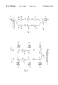
- FIG. 1 schematically depicts an optical wavelength division multiplexed point-to-point system with duplicated paths including a working path and a protection path, and
- FIG. 2 schematically shows the receiving end of an optical WDM point-to-point system with a working path and protection path, the protection path being configured in accordance with the invention.
- FIG. 3 shows, as a block diagram, the optical fibre pre-amplifier for use in the system of FIGS. 1 and 2 .
- the WDM point-to-point system shown in FIG. 1 comprises WDM transmitters 10 each of which sends a payload data signal modulated onto a carrier wavelength to a multiplexer 11 which, in turn, combines the signals onto a single fibre 12 .
- This fibre 12 is then split into two paths 20 , 20 ′ by means of a 1 ⁇ 2 or 2 ⁇ 2 fibre coupler.
- the multiplexed signals in each path are thus propagated in parallel through a first optical amplifier, or power amplifier 13 , 13 ′, through optical line amplifiers 14 , 14 ′, only one of which is shown in each path in this example for convenience, and through a final amplifier or pre-amplifier 15 , 15 ′, respectively.
- the fibres of the two paths 20 , 20 ′ are then recombined before entering a demultiplexer 16 , which separates the signals according to wavelength and passes the signals to a WDM receiver 17 .
- the optical power amplifiers 13 , 13 ′ and line amplifiers 14 , 14 ′ may be constituted by any suitable optical amplifiers, including, but not limited to, optical repeaters of the regenerative type or optical fibre amplifiers such as disclosed in the above-mentioned reference.
- FIG. 2 shows the receiving end of the point-to-point WDM system. From this figure it is apparent that optical taps 18 , 18 ′ and associated detectors 19 , 19 ′ are provided on the two lines 20 , 20 ′ before and after the pre-amplifiers 15 , 15 ′.
- the detectors preferably take the form of monitoring PIN diode receivers, although it will be understood that any suitable device capable of converting the tapped optical signal into electrical energy could be utilized.
- similar optical taps and associated detectors are provided before and after each amplifier in both lines 20 , 20 ′ for extracting a small portion of the incident optical power to enable the connections and functions of the paths to be monitored at each stage.
- a further optical tap 18 and 18 ′ and associated detectors 21 , 19 ′ are connected to each of the fibres directly upstream of the recombining of the two paths 20 and 20 ′ in an optical combiner 22 .
- the signals are propagated from the multiplexer 11 to the demultiplexer 16 only by the working path 20 ′.
- all the amplifiers 13 ′, 14 ′, 15 ′ on this path are operating normally to amplify the optical signals.
- the signals are propagated through the power amplifier 13 and the line amplifiers 14 up to the pre-amplifier 15 .
- the normal operation of the power amplifier 13 and line amplifiers 14 of the protection path 20 is necessary to enable detection of any interruption in transmission due to a fibre break or a faulty connection by the associated detectors 19 upstream of the pre-amplifier 15 .
- the final amplifier 15 on the protection path is configured to block the incoming signals.
- FIG. 3 shows the principle of operation of the optical fibre amplifier 15 utilised as a pre-amplifier 15 in the protection path 20 .
- the amplifier comprises a fibre section 30 doped with rare earth ions or a similar fluorescent substance into which is coupled the optical input signal.
- Optical pumping energy from a pump laser 31 is likewise coupled into the doped fibre section 30 through an optical coupler 32 .
- the pump laser 31 is driven by a drive current supplied by a drive circuit 33 .
- the drive circuit 33 is in turn controlled by a control circuit 34 .
- This control circuit may be arranged in the optical amplifier unit or be located remote from the amplifier 15 and connected via a separate and possibly dedicated supervisory or control channel.
- the control circuit may contain dedicated circuitry but preferably incorporates a microprocessor or similar data processing means with associated memory.
- the drive circuit 33 is controlled by the control circuit 34 to supply a low power to the pump laser 31 which accordingly supplies a low optical pumping energy to the doped fibre 30 .
- the optical pumping energy to the doped fibre section 30 falls below a certain level, substantially all the light energy of the incoming optical signals will be absorbed and the signals attenuated rather than amplified.
- the amplifier 15 is described as ‘glowing’. However, amplified spontaneous emission will always occur while optical power from the laser is pumped to the doped fibre section. Accordingly a low power light signal will be present at the output of this pre-amplifier 15 .
- a modulating generator 35 operating at a predetermined low frequency is likewise connected to the drive circuit 33 and controlled by the control circuit 34 .
- the modulating generator 35 modulates the pump laser drive current.
- the modulation frequency is sufficiently low, i.e. lower than the spontaneous lifetime of the excited electrons in the doped fibre 30 , the resulting modulation of the pump laser light will cause the modulation of the amplified spontaneous emission (ASE).
- the modulated ASE which serves as a pilot or control tone can then be detected by the last PIN diode receiver 21 disposed directly upstream of the optical combiner 22 .
- modulation can be imposed elsewhere in the optical fibre amplifier 15 .
- modulated light could be coupled directly into the active fibre together with the pumping radiation, or alternatively directly into the output fibre of the optical amplifier using an optical coupler.
- the pin diode receiver 21 can reliably distinguish the light energy originating from the protection path from any reflections of the signals propagated through the working path caused by imperfect connections at the optical combiner 22 or the demultiplexer 16 .
- the pin diode receiver 21 includes a synchronous receiver tuned to the ASE modulation frequency to increase the detection sensitivity. This allows the glowing power of the pump laser to be reduced even further to render negligible any potential risk of cross talk between the control tone and the propagated signal at the receiver 16 , 17 .
- the ratio of the output powers of the pre-amplifier 15 ′ of the working section and the pre-amplifier 15 of the protection section is selected to minimise crosstalk but also to enable the PIN diode receivers 21 , 19 ′ on each path to clearly distinguish between the working section light signal and the protection section light signal, so that loss of power in either the working section or the protection section can be reliable detected.
- a ratio of around 30 dB has proved to be suitable for this purpose.
- the modulating generator 35 is configured to intervene permanently to modulate the pump laser drive current by a low frequency signal i.e. even when the amplifier 15 is operating at normal power to amplify the incoming signals.
- the low modulation level necessary for ensuring detection by the PIN diode receiver 21 when the pre-amplifier 15 is operating at reduced power will produce a substantially negligible ripple on the propagated data signals when the protection path is active, and therefore will not adversely affect normal traffic flow.
- the uppermost optical fibre line 20 ′ shown in FIGS. 1 and 2 will be active while the lowermost line 20 is in standby.
- Signals transmitted by the WDM transmitter 10 and multiplexed onto the single fibre section 12 by the multiplexer 11 will be propagated through the working path 20 to the demultiplexer 16 and WDM receiver 17 , and also through the protecting path 20 as far as the pre-amplifier 15 .
- this amplifier 15 is configured to attenuate incoming signals, i.e. the pump laser 31 of this latter amplifier 15 is driven at low power (‘glowing’).
- the pump laser light is also modulated by a low frequency signal generated by the signal generator 35 causing a control tone to be superimposed on the ASE generated in the doped fibre 30 .
- the PIN diode receivers 19 ′ along the working path monitor the level of the transmitted signal to determine whether the working path is functioning correctly.
- the PIN diode receivers 19 upstream of the pre-amplifier in the protection path likewise monitor the light power level to ascertain the integrity of this section of the line.
- the PIN diode receiver 21 at the input of the optical combiner 22 also monitors the line but specifically detects the presence or absence of the control tone.
- the pre-amplifier 15 ′ of the working section will then be turned off, or alternatively configured to ‘glow’, and the pre-amplifier 15 of the protection path 20 can be switched into operation to enable the transmitted light signals modulated with data to be propagated through the whole of the protection path 20 to the receivers 17 .
- the pre-amplifier 15 ′ of the working section 20 ′ could also be provided with a means for modulating the ASE at least when this amplifier is configured to block optical input signals after a path switch.
- the final PIN diode receiver 19 ′ of the working path 20 ′ and the PIN diode receiver 21 of the protection path 20 could both be designed to selectively detect a loss of power of the transmitted signal or an absence of control tone. In this way full redundancy can be provided wherein either one of the paths may be configured as the active path while the other is in standby.
- the invention is not limited to systems providing redundancy.
- the invention also has application in systems wherein two or more lines carrying information from different sources arrive at a single receiver.
- the pre-amplifiers or final line amplifiers of the remaining links are configured to block the transmitted signals.
- these lines can be continually monitored through to the receiving section so that any fault arising may be detected and if possible repaired before the line is brought into service.
- modulation frequencies could then be used to modulate the pumping light radiation of each line in standby so that the condition of each line can be ascertained.
- the arrangement according to the invention could be utilized in an optical system, which may be wavelength division multiplexed, having a hub comprising a plurality of line sections connected in series, wherein individual sections can be turned off, i.e. the associated optical fibre amplifier driven to “glow”, to enable different path configurations between lines running into and out of the hub.
- the reliability of the system can be significantly improved using the arrangement and method according to the invention by permitting the full monitoring of any standby sections.
Landscapes
- Engineering & Computer Science (AREA)
- Computer Networks & Wireless Communication (AREA)
- Signal Processing (AREA)
- Physics & Mathematics (AREA)
- Electromagnetism (AREA)
- Optical Communication System (AREA)
- Lasers (AREA)
- Semiconductor Lasers (AREA)
- Maintenance And Management Of Digital Transmission (AREA)
- Monitoring And Testing Of Transmission In General (AREA)
Applications Claiming Priority (3)
| Application Number | Priority Date | Filing Date | Title |
|---|---|---|---|
| EP98115350 | 1998-08-14 | ||
| EP98115350A EP0981212A1 (de) | 1998-08-14 | 1998-08-14 | Wegüberwachung in optischen Übertragungssystemen |
| PCT/EP1999/005671 WO2000010268A1 (en) | 1998-08-14 | 1999-08-05 | Path monitoring in optical communication systems |
Publications (1)
| Publication Number | Publication Date |
|---|---|
| US6654513B1 true US6654513B1 (en) | 2003-11-25 |
Family
ID=8232462
Family Applications (1)
| Application Number | Title | Priority Date | Filing Date |
|---|---|---|---|
| US09/762,995 Expired - Lifetime US6654513B1 (en) | 1998-08-14 | 1999-08-05 | Path monitoring in optical communication systems |
Country Status (9)
| Country | Link |
|---|---|
| US (1) | US6654513B1 (de) |
| EP (2) | EP0981212A1 (de) |
| JP (1) | JP2002523921A (de) |
| CN (1) | CN1157010C (de) |
| AT (1) | ATE237891T1 (de) |
| AU (1) | AU5510499A (de) |
| CA (1) | CA2340436A1 (de) |
| DE (1) | DE69906988T2 (de) |
| WO (1) | WO2000010268A1 (de) |
Cited By (10)
| Publication number | Priority date | Publication date | Assignee | Title |
|---|---|---|---|---|
| US20050157978A1 (en) * | 2003-03-28 | 2005-07-21 | Fujitsu Limited | System for detecting fault in optical-transmission path |
| US20050179993A1 (en) * | 2004-02-13 | 2005-08-18 | Jasti Chandra S. | Optical amplifier apparatus and method |
| US7356228B1 (en) | 2007-01-12 | 2008-04-08 | International Business Machines Corporation | Fiber optic cable systems and methods incorporating a luminescent compound-containing layer to identify cracks |
| US20110116798A1 (en) * | 2009-11-16 | 2011-05-19 | Fujitsu Limited | Optical communication network and supervisory control device |
| US20140321844A1 (en) * | 2013-04-28 | 2014-10-30 | Eci Telecom Ltd. | Method of carrying out fast switching in optical communication networks |
| US10320513B2 (en) * | 2015-05-26 | 2019-06-11 | Zte Corporation | Distributed automatic power optimization system and method |
| US20220321227A1 (en) * | 2021-03-31 | 2022-10-06 | Japan Display Inc. | Communication device and communication method |
| US11575241B2 (en) | 2020-12-11 | 2023-02-07 | Ii-Vi Delaware, Inc. | Optical amplifier modules |
| US11588295B2 (en) | 2019-11-01 | 2023-02-21 | Ii-Vi Delaware, Inc. | Pump modulation for optical amplifier link communication |
| CN116031750A (zh) * | 2021-10-27 | 2023-04-28 | Ii-Vi特拉华有限公司 | 用于纤维耦合式高功率激光源的眼部安全联锁装置 |
Families Citing this family (7)
| Publication number | Priority date | Publication date | Assignee | Title |
|---|---|---|---|---|
| US7039319B1 (en) * | 2001-08-07 | 2006-05-02 | Cisco Technology, Inc. | DWDM laser frequency control |
| EP1453226B1 (de) * | 2001-12-03 | 2012-02-01 | Fujitsu Limited | Optisches kommunikationssystem |
| DE10246612A1 (de) | 2002-10-07 | 2004-04-15 | Marconi Communications Gmbh | Optisches Nachrichten verarbeitendes System, Komponenten und Betriebsverfahren dafür |
| JP2006157245A (ja) * | 2004-11-26 | 2006-06-15 | Pioneer Electronic Corp | 信号送受信装置及び信号送受信方法 |
| JP5050931B2 (ja) | 2008-03-04 | 2012-10-17 | 日本電気株式会社 | 光伝送システム、光伝送システムで用いられる光送受信装置、及び端末側送受信装置、並びに光伝送方法 |
| CN110082070B (zh) * | 2019-05-24 | 2021-03-12 | 广东电网有限责任公司 | 跳纤测试方法 |
| CN112394273B (zh) * | 2019-08-12 | 2023-03-24 | 芯恩(青岛)集成电路有限公司 | 电路的查线系统及方法 |
Citations (7)
| Publication number | Priority date | Publication date | Assignee | Title |
|---|---|---|---|---|
| EP0753913A1 (de) | 1995-07-06 | 1997-01-15 | Nec Corporation | Faseroptischer Verstärker |
| US5668658A (en) * | 1995-02-28 | 1997-09-16 | Nec Corporation | Transfer of repeater information signals in in-line optical amplifier repeater system |
| EP0851704A2 (de) | 1996-12-31 | 1998-07-01 | Lucent Technologies Inc. | Optisches System zur Reservenumschaltung |
| US5917969A (en) * | 1998-02-17 | 1999-06-29 | Polaroid Corporation | Laser modulator |
| US6215583B1 (en) * | 1996-09-13 | 2001-04-10 | Telefonaktiebolaget Lm Ericsson (Publ) | System with feedback controlled optical amplifiers |
| US20010017729A1 (en) * | 1996-05-02 | 2001-08-30 | Yasushi Sugaya | Controller which controls a variable optical attenuator to control the power level of a wavelength-multiplexed optical signal when the number of channels are varied |
| US20010030796A1 (en) * | 1997-01-14 | 2001-10-18 | California Institute Of Technology, A California Corporation | Methods and devices based on brillouin selective sideband amplification |
-
1998
- 1998-08-14 EP EP98115350A patent/EP0981212A1/de not_active Withdrawn
-
1999
- 1999-08-05 AT AT99941522T patent/ATE237891T1/de not_active IP Right Cessation
- 1999-08-05 US US09/762,995 patent/US6654513B1/en not_active Expired - Lifetime
- 1999-08-05 CA CA002340436A patent/CA2340436A1/en not_active Abandoned
- 1999-08-05 CN CNB998099384A patent/CN1157010C/zh not_active Expired - Fee Related
- 1999-08-05 JP JP2000565619A patent/JP2002523921A/ja active Pending
- 1999-08-05 AU AU55104/99A patent/AU5510499A/en not_active Abandoned
- 1999-08-05 EP EP99941522A patent/EP1104603B1/de not_active Expired - Lifetime
- 1999-08-05 DE DE69906988T patent/DE69906988T2/de not_active Expired - Lifetime
- 1999-08-05 WO PCT/EP1999/005671 patent/WO2000010268A1/en not_active Ceased
Patent Citations (7)
| Publication number | Priority date | Publication date | Assignee | Title |
|---|---|---|---|---|
| US5668658A (en) * | 1995-02-28 | 1997-09-16 | Nec Corporation | Transfer of repeater information signals in in-line optical amplifier repeater system |
| EP0753913A1 (de) | 1995-07-06 | 1997-01-15 | Nec Corporation | Faseroptischer Verstärker |
| US20010017729A1 (en) * | 1996-05-02 | 2001-08-30 | Yasushi Sugaya | Controller which controls a variable optical attenuator to control the power level of a wavelength-multiplexed optical signal when the number of channels are varied |
| US6215583B1 (en) * | 1996-09-13 | 2001-04-10 | Telefonaktiebolaget Lm Ericsson (Publ) | System with feedback controlled optical amplifiers |
| EP0851704A2 (de) | 1996-12-31 | 1998-07-01 | Lucent Technologies Inc. | Optisches System zur Reservenumschaltung |
| US20010030796A1 (en) * | 1997-01-14 | 2001-10-18 | California Institute Of Technology, A California Corporation | Methods and devices based on brillouin selective sideband amplification |
| US5917969A (en) * | 1998-02-17 | 1999-06-29 | Polaroid Corporation | Laser modulator |
Non-Patent Citations (3)
| Title |
|---|
| International Search Report relating to PCT/EP99/05671, Date: Jan. 12, 2000. |
| K Shimizu et al.: "Supervisory Signal Transmission Experiments over 10,000 KM by Modulated ASE of EDFAS Electronics Letters" vol. 29, No. 12, Jun. 10, 1993, pp. 1081-1083 (English). |
| PJ Chidgey et al.: "Diverse Routing of Multiplexed Signals in an Amplified Wavelenght Routed Network" Proceedings of the European Conference on Optical Communication (EC, Amsterdam, Sep. 16-20, 1990, Regular Papers, vol. 1, No. CONF 16, pp. 157-160 (XP000449197) (English). |
Cited By (20)
| Publication number | Priority date | Publication date | Assignee | Title |
|---|---|---|---|---|
| US20050157978A1 (en) * | 2003-03-28 | 2005-07-21 | Fujitsu Limited | System for detecting fault in optical-transmission path |
| US7428354B2 (en) * | 2003-03-28 | 2008-09-23 | Fujitsu Limited | System for detecting fault in optical-transmission path |
| US20050179993A1 (en) * | 2004-02-13 | 2005-08-18 | Jasti Chandra S. | Optical amplifier apparatus and method |
| US6980357B2 (en) * | 2004-02-13 | 2005-12-27 | General Instrument Corporation | Optical amplifier apparatus and method |
| US20060056012A1 (en) * | 2004-02-13 | 2006-03-16 | Jasti Chandra S | Optical amplifier apparatus and method |
| US7119948B2 (en) | 2004-02-13 | 2006-10-10 | General Instrument Corporation | Optical amplifier apparatus and method |
| US7356228B1 (en) | 2007-01-12 | 2008-04-08 | International Business Machines Corporation | Fiber optic cable systems and methods incorporating a luminescent compound-containing layer to identify cracks |
| US20080170221A1 (en) * | 2007-01-12 | 2008-07-17 | International Business Machines Corporation | Fiber optic cable systems and methods incorporating a luminescent compound-containing layer to identify cracks |
| US7512299B2 (en) | 2007-01-12 | 2009-03-31 | International Business Machines Corporation | Fiber optic cable systems and methods incorporating a luminescent compound-containing layer to identify cracks |
| US8787757B2 (en) * | 2009-11-16 | 2014-07-22 | Fujitsu Limited | Optical communication network and supervisory control device |
| US20110116798A1 (en) * | 2009-11-16 | 2011-05-19 | Fujitsu Limited | Optical communication network and supervisory control device |
| US20140321844A1 (en) * | 2013-04-28 | 2014-10-30 | Eci Telecom Ltd. | Method of carrying out fast switching in optical communication networks |
| US9209895B2 (en) * | 2013-04-28 | 2015-12-08 | Eci Telecom Ltd. | Method of carrying out fast switching in optical communication networks |
| US10320513B2 (en) * | 2015-05-26 | 2019-06-11 | Zte Corporation | Distributed automatic power optimization system and method |
| US11588295B2 (en) | 2019-11-01 | 2023-02-21 | Ii-Vi Delaware, Inc. | Pump modulation for optical amplifier link communication |
| US12062882B2 (en) | 2019-11-01 | 2024-08-13 | Ii-Vi Delaware, Inc. | Pump modulation for optical amplifier link communication |
| US11575241B2 (en) | 2020-12-11 | 2023-02-07 | Ii-Vi Delaware, Inc. | Optical amplifier modules |
| US20220321227A1 (en) * | 2021-03-31 | 2022-10-06 | Japan Display Inc. | Communication device and communication method |
| US11750295B2 (en) * | 2021-03-31 | 2023-09-05 | Japan Display Inc. | Communication device and communication method |
| CN116031750A (zh) * | 2021-10-27 | 2023-04-28 | Ii-Vi特拉华有限公司 | 用于纤维耦合式高功率激光源的眼部安全联锁装置 |
Also Published As
| Publication number | Publication date |
|---|---|
| CN1314036A (zh) | 2001-09-19 |
| DE69906988D1 (de) | 2003-05-22 |
| ATE237891T1 (de) | 2003-05-15 |
| EP1104603A1 (de) | 2001-06-06 |
| EP1104603B1 (de) | 2003-04-16 |
| AU5510499A (en) | 2000-03-06 |
| EP0981212A1 (de) | 2000-02-23 |
| CN1157010C (zh) | 2004-07-07 |
| DE69906988T2 (de) | 2004-02-12 |
| JP2002523921A (ja) | 2002-07-30 |
| WO2000010268A1 (en) | 2000-02-24 |
| CA2340436A1 (en) | 2000-02-24 |
Similar Documents
| Publication | Publication Date | Title |
|---|---|---|
| EP1104603B1 (de) | Wegüberwachung in optischen übertragungssystemen | |
| US7260324B2 (en) | Automatic optical power management in optical communications system | |
| US5005937A (en) | Optical branching equipment and optical network using the same | |
| JP4093937B2 (ja) | 光伝送システム | |
| US6215565B1 (en) | Method of and system for diagnosing optical system failures | |
| US7957643B2 (en) | Method and apparatus for automatically controlling optical signal power in optical transmission systems | |
| JP2002252595A (ja) | 光増幅器 | |
| JPH0383427A (ja) | 送信信号の増幅器を含む光ファイバ通信回線及び該回線のための増幅器 | |
| JP2002221743A (ja) | 光増幅器、光ファイバラマン光増幅器、及び光システム | |
| EP1959587A1 (de) | Verfahren, vorrichtung und system zur bearbeitung von glasfaserleitungsfehlern | |
| US6344915B1 (en) | System and method for shutting off an optical energy source in a communication system having optical amplifiers | |
| US7218442B2 (en) | Optical communications system with fiber break detection in the presence of Raman amplification | |
| US7729613B2 (en) | Apparatus for optical path monitoring and an optical shutter for preventing signal transimission in a faulty optical path | |
| US9264134B2 (en) | Automatic laser shutdown and recovery in response to a link break | |
| US7864389B2 (en) | Method of controlling optical amplifier located along an optical link | |
| US6839515B1 (en) | Method for establishing a communication on a standby link in optical transmission facilities | |
| US7551857B2 (en) | Optical transmission system | |
| US7136584B2 (en) | Optical output power automatic attenuation circuit for optical communication apparatus | |
| JP2004228761A (ja) | 中継装置およびラマン増幅中継システム | |
| JP3045288B2 (ja) | 光信号出力停止の方法とその回路 | |
| JP4615155B2 (ja) | 光通信方法およびそのシステム | |
| US9209895B2 (en) | Method of carrying out fast switching in optical communication networks | |
| JP3670341B2 (ja) | 光送信装置 | |
| KR20030094844A (ko) | 파장분할 다중화 시스템 및 그것을 위한 경보발생 억제 및레이저 차단 방법 | |
| JPH09233023A (ja) | 光伝送システムの切替方法及び光増幅器 |
Legal Events
| Date | Code | Title | Description |
|---|---|---|---|
| AS | Assignment |
Owner name: TELEFONAKTIEBOLAGET LM ERICSSON (PUBL), SWEDEN Free format text: ASSIGNMENT OF ASSIGNORS INTEREST;ASSIGNORS:LIDEN, FREDRIK;SANDELL, JOHAN;WINGSTRAND, SVEN;AND OTHERS;REEL/FRAME:012081/0059;SIGNING DATES FROM 20010404 TO 20010422 |
|
| STCF | Information on status: patent grant |
Free format text: PATENTED CASE |
|
| FPAY | Fee payment |
Year of fee payment: 4 |
|
| FPAY | Fee payment |
Year of fee payment: 8 |
|
| FPAY | Fee payment |
Year of fee payment: 12 |