US6655602B2 - Fuel injector having a hydraulically actuated control valve and hydraulic system using same - Google Patents
Fuel injector having a hydraulically actuated control valve and hydraulic system using same Download PDFInfo
- Publication number
- US6655602B2 US6655602B2 US09/961,612 US96161201A US6655602B2 US 6655602 B2 US6655602 B2 US 6655602B2 US 96161201 A US96161201 A US 96161201A US 6655602 B2 US6655602 B2 US 6655602B2
- Authority
- US
- United States
- Prior art keywords
- valve member
- passage
- spool
- high pressure
- control
- Prior art date
- Legal status (The legal status is an assumption and is not a legal conclusion. Google has not performed a legal analysis and makes no representation as to the accuracy of the status listed.)
- Expired - Fee Related, expires
Links
- 239000000446 fuel Substances 0.000 title claims abstract description 46
- 239000012530 fluid Substances 0.000 claims abstract description 87
- 238000004891 communication Methods 0.000 claims abstract description 35
- 238000000034 method Methods 0.000 claims description 5
- 230000000903 blocking effect Effects 0.000 claims description 4
- 238000002347 injection Methods 0.000 description 17
- 239000007924 injection Substances 0.000 description 17
- 239000003921 oil Substances 0.000 description 6
- 238000002485 combustion reaction Methods 0.000 description 3
- 238000002360 preparation method Methods 0.000 description 2
- 230000004913 activation Effects 0.000 description 1
- 230000003993 interaction Effects 0.000 description 1
- 239000010687 lubricating oil Substances 0.000 description 1
- 238000012986 modification Methods 0.000 description 1
- 230000004048 modification Effects 0.000 description 1
- 238000009428 plumbing Methods 0.000 description 1
- 238000005086 pumping Methods 0.000 description 1
- 239000007921 spray Substances 0.000 description 1
Images



Classifications
-
- F—MECHANICAL ENGINEERING; LIGHTING; HEATING; WEAPONS; BLASTING
- F02—COMBUSTION ENGINES; HOT-GAS OR COMBUSTION-PRODUCT ENGINE PLANTS
- F02M—SUPPLYING COMBUSTION ENGINES IN GENERAL WITH COMBUSTIBLE MIXTURES OR CONSTITUENTS THEREOF
- F02M63/00—Other fuel-injection apparatus having pertinent characteristics not provided for in groups F02M39/00 - F02M57/00 or F02M67/00; Details, component parts, or accessories of fuel-injection apparatus, not provided for in, or of interest apart from, the apparatus of groups F02M39/00 - F02M61/00 or F02M67/00; Combination of fuel pump with other devices, e.g. lubricating oil pump
- F02M63/0012—Valves
- F02M63/0014—Valves characterised by the valve actuating means
- F02M63/0028—Valves characterised by the valve actuating means hydraulic
- F02M63/0029—Valves characterised by the valve actuating means hydraulic using a pilot valve controlling a hydraulic chamber
-
- F—MECHANICAL ENGINEERING; LIGHTING; HEATING; WEAPONS; BLASTING
- F02—COMBUSTION ENGINES; HOT-GAS OR COMBUSTION-PRODUCT ENGINE PLANTS
- F02M—SUPPLYING COMBUSTION ENGINES IN GENERAL WITH COMBUSTIBLE MIXTURES OR CONSTITUENTS THEREOF
- F02M47/00—Fuel-injection apparatus operated cyclically with fuel-injection valves actuated by fluid pressure
- F02M47/04—Fuel-injection apparatus operated cyclically with fuel-injection valves actuated by fluid pressure using fluid, other than fuel, for injection-valve actuation
- F02M47/043—Fluid pressure acting on injection-valve in the period of non-injection to keep it closed
-
- F—MECHANICAL ENGINEERING; LIGHTING; HEATING; WEAPONS; BLASTING
- F02—COMBUSTION ENGINES; HOT-GAS OR COMBUSTION-PRODUCT ENGINE PLANTS
- F02M—SUPPLYING COMBUSTION ENGINES IN GENERAL WITH COMBUSTIBLE MIXTURES OR CONSTITUENTS THEREOF
- F02M47/00—Fuel-injection apparatus operated cyclically with fuel-injection valves actuated by fluid pressure
- F02M47/06—Other fuel injectors peculiar thereto
-
- F—MECHANICAL ENGINEERING; LIGHTING; HEATING; WEAPONS; BLASTING
- F02—COMBUSTION ENGINES; HOT-GAS OR COMBUSTION-PRODUCT ENGINE PLANTS
- F02M—SUPPLYING COMBUSTION ENGINES IN GENERAL WITH COMBUSTIBLE MIXTURES OR CONSTITUENTS THEREOF
- F02M57/00—Fuel-injectors combined or associated with other devices
- F02M57/02—Injectors structurally combined with fuel-injection pumps
- F02M57/022—Injectors structurally combined with fuel-injection pumps characterised by the pump drive
- F02M57/025—Injectors structurally combined with fuel-injection pumps characterised by the pump drive hydraulic, e.g. with pressure amplification
-
- F—MECHANICAL ENGINEERING; LIGHTING; HEATING; WEAPONS; BLASTING
- F02—COMBUSTION ENGINES; HOT-GAS OR COMBUSTION-PRODUCT ENGINE PLANTS
- F02M—SUPPLYING COMBUSTION ENGINES IN GENERAL WITH COMBUSTIBLE MIXTURES OR CONSTITUENTS THEREOF
- F02M59/00—Pumps specially adapted for fuel-injection and not provided for in groups F02M39/00 -F02M57/00, e.g. rotary cylinder-block type of pumps
- F02M59/02—Pumps specially adapted for fuel-injection and not provided for in groups F02M39/00 -F02M57/00, e.g. rotary cylinder-block type of pumps of reciprocating-piston or reciprocating-cylinder type
- F02M59/10—Pumps specially adapted for fuel-injection and not provided for in groups F02M39/00 -F02M57/00, e.g. rotary cylinder-block type of pumps of reciprocating-piston or reciprocating-cylinder type characterised by the piston-drive
- F02M59/105—Pumps specially adapted for fuel-injection and not provided for in groups F02M39/00 -F02M57/00, e.g. rotary cylinder-block type of pumps of reciprocating-piston or reciprocating-cylinder type characterised by the piston-drive hydraulic drive
-
- F—MECHANICAL ENGINEERING; LIGHTING; HEATING; WEAPONS; BLASTING
- F02—COMBUSTION ENGINES; HOT-GAS OR COMBUSTION-PRODUCT ENGINE PLANTS
- F02M—SUPPLYING COMBUSTION ENGINES IN GENERAL WITH COMBUSTIBLE MIXTURES OR CONSTITUENTS THEREOF
- F02M59/00—Pumps specially adapted for fuel-injection and not provided for in groups F02M39/00 -F02M57/00, e.g. rotary cylinder-block type of pumps
- F02M59/38—Pumps characterised by adaptations to special uses or conditions
- F02M59/42—Pumps characterised by adaptations to special uses or conditions for starting of engines
-
- F—MECHANICAL ENGINEERING; LIGHTING; HEATING; WEAPONS; BLASTING
- F02—COMBUSTION ENGINES; HOT-GAS OR COMBUSTION-PRODUCT ENGINE PLANTS
- F02M—SUPPLYING COMBUSTION ENGINES IN GENERAL WITH COMBUSTIBLE MIXTURES OR CONSTITUENTS THEREOF
- F02M59/00—Pumps specially adapted for fuel-injection and not provided for in groups F02M39/00 -F02M57/00, e.g. rotary cylinder-block type of pumps
- F02M59/44—Details, components parts, or accessories not provided for in, or of interest apart from, the apparatus of groups F02M59/02 - F02M59/42; Pumps having transducers, e.g. to measure displacement of pump rack or piston
- F02M59/46—Valves
-
- F—MECHANICAL ENGINEERING; LIGHTING; HEATING; WEAPONS; BLASTING
- F02—COMBUSTION ENGINES; HOT-GAS OR COMBUSTION-PRODUCT ENGINE PLANTS
- F02M—SUPPLYING COMBUSTION ENGINES IN GENERAL WITH COMBUSTIBLE MIXTURES OR CONSTITUENTS THEREOF
- F02M2200/00—Details of fuel-injection apparatus, not otherwise provided for
- F02M2200/21—Fuel-injection apparatus with piezoelectric or magnetostrictive elements
-
- F—MECHANICAL ENGINEERING; LIGHTING; HEATING; WEAPONS; BLASTING
- F02—COMBUSTION ENGINES; HOT-GAS OR COMBUSTION-PRODUCT ENGINE PLANTS
- F02M—SUPPLYING COMBUSTION ENGINES IN GENERAL WITH COMBUSTIBLE MIXTURES OR CONSTITUENTS THEREOF
- F02M2200/00—Details of fuel-injection apparatus, not otherwise provided for
- F02M2200/60—Fuel-injection apparatus having means for facilitating the starting of engines, e.g. with valves or fuel passages for keeping residual pressure in common rails
-
- F—MECHANICAL ENGINEERING; LIGHTING; HEATING; WEAPONS; BLASTING
- F02—COMBUSTION ENGINES; HOT-GAS OR COMBUSTION-PRODUCT ENGINE PLANTS
- F02M—SUPPLYING COMBUSTION ENGINES IN GENERAL WITH COMBUSTIBLE MIXTURES OR CONSTITUENTS THEREOF
- F02M59/00—Pumps specially adapted for fuel-injection and not provided for in groups F02M39/00 -F02M57/00, e.g. rotary cylinder-block type of pumps
- F02M59/44—Details, components parts, or accessories not provided for in, or of interest apart from, the apparatus of groups F02M59/02 - F02M59/42; Pumps having transducers, e.g. to measure displacement of pump rack or piston
- F02M59/46—Valves
- F02M59/466—Electrically operated valves, e.g. using electromagnetic or piezoelectric operating means
-
- F—MECHANICAL ENGINEERING; LIGHTING; HEATING; WEAPONS; BLASTING
- F02—COMBUSTION ENGINES; HOT-GAS OR COMBUSTION-PRODUCT ENGINE PLANTS
- F02M—SUPPLYING COMBUSTION ENGINES IN GENERAL WITH COMBUSTIBLE MIXTURES OR CONSTITUENTS THEREOF
- F02M59/00—Pumps specially adapted for fuel-injection and not provided for in groups F02M39/00 -F02M57/00, e.g. rotary cylinder-block type of pumps
- F02M59/44—Details, components parts, or accessories not provided for in, or of interest apart from, the apparatus of groups F02M59/02 - F02M59/42; Pumps having transducers, e.g. to measure displacement of pump rack or piston
- F02M59/46—Valves
- F02M59/466—Electrically operated valves, e.g. using electromagnetic or piezoelectric operating means
- F02M59/468—Electrically operated valves, e.g. using electromagnetic or piezoelectric operating means using piezoelectric operating means
Definitions
- This invention relates generally to hydraulic systems, and more particularly to fuel injectors having hydraulically actuated control valves.
- a pressure communication passage extends from a pilot valve to the top of the needle valve member, with a branch of this passage running to the underside of a spool valve to control movement of the same.
- a fuel injector including such a configuration is described in U.S. Pat. No. 5,833,146, issued to Hefler on Nov. 10, 1998. While this design has performed well, a substantial amount of fluid flow past the pilot valve is required to move the spool valve due to the relatively large amount of fluid that must be displaced by movement of the spool valve member.
- the present invention is directed to overcoming one or more of the problems as set forth above.
- a valve assembly in one aspect of the present invention, includes a valve body that defines a first passage, a second passage and a variable pressure passage.
- a spool valve member is positioned in the valve body and is movable between a first position in which the first passage is open to the variable pressure passage and a second position in which the second passage is open to the variable pressure passage.
- a spool control volume is defined by at least one of the valve body and the spool valve member.
- a control valve member is positioned in the valve body and is movable between an open position in which the first passage is in fluid communication with the spool control volume and a closed position in which the first passage is blocked from fluid communication with the spool control volume.
- the control valve member includes a hydraulic surface that defines a hydraulic force direction.
- a biaser is operably in contact with the control valve member to produce a biasing force in opposition to the hydraulic force direction.
- a hydraulically actuated device in another aspect of the present invention, includes a device body that defines a high pressure passage, a low pressure passage and a variable pressure passage.
- a source of high pressure actuation fluid is connected to the high pressure passage.
- a low pressure reservoir is connected to the low pressure passage.
- a spool valve member is movably positioned in the device body.
- a spool control volume is defined by at least one of the device body and the spool valve member.
- a control valve member is movably positioned in the device body and includes a hydraulic surface that defines a hydraulic force direction. The hydraulic surface is exposed to the high pressure passage when the control valve member is in a first position and is exposed to the low pressure passage when the control valve member is in a second position.
- the hydraulic surface is exposed to fluid pressure in a pressure cavity that is fluidly isolated from the spool control volume.
- a biaser is operably in contact with the control valve member to produce a biasing force in opposition to the hydraulic force direction.
- a reciprocating piston is included in the hydraulic device that has a hydraulic surface exposed to fluid pressure in the variable pressure passage.
- a method of operating a control valve includes providing a valve assembly that includes a valve body which defines a low pressure passage and a high pressure passage.
- a pilot valve member, a control valve member and a spool valve member are included in the valve body.
- the pilot valve member is moved from a first position to a second position to expose a hydraulic surface of the control valve member to the low pressure passage.
- the control valve member is then moved to a closed position blocking a control pressure surface of the spool valve member from the high pressure passage.
- the spool valve member is moved from a first position to a second position.
- the pilot valve member is then returned to the first position to expose the hydraulic surface of the control valve member to the high pressure passage.
- the control valve member is next moved to an open position exposing the control pressure surface of the spool valve member to the high pressure passage.
- the spool valve member is then moved to the first position.
- FIG. 1 is a diagrammatic representation of a hydraulic system that includes a hydraulic device according to the present invention
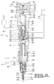
- FIG. 2 is a diagrammatic representation of hydraulically-actuated electronically-controlled fuel injector according to the present invention.
- FIG. 3 is a sectioned side view of the spool valve assembly portion of the fuel injector of FIG. 2 .
- hydraulic system 10 includes a hydraulically-actuated device 11 , such as a fuel injector or an engine valve.
- a control valve 12 alternately opens hydraulically-actuated device 11 to a source of high pressure fluid 13 or a low pressure fluid reservoir 14 .
- the state of control valve 12 is controlled by energizing and de-energizing an electrical actuating device 16 , which is preferably a solenoid but could also be another suitable device such as a piezoelectric actuator.
- Electrical actuating device 16 is controlled in its operation by a conventional electronic control module 15 via communication line 29 .
- Control valve 12 includes a valve body 19 that defines a high pressure inlet 20 that is connected to the source of high pressure fluid 13 via a high pressure supply line 26 .
- valve body 19 also defines a pair of low pressure vents 21 and a low pressure drain 22 . These three low pressure openings communicate with low pressure fluid reservoir 14 via a low pressure passage 27 .
- Fuel injector 30 includes an injector body 31 made up of various components that are attached to one another in a manner well known in the art and a substantial number of internal movable components positioned as they would be just prior to an injection event.
- Actuation fluid which is preferably high pressure oil, can flow into a high pressure actuation fluid passage 46 that is defined by injector body 31 via an actuation fluid inlet 20 and high pressure supply line 26 from the source of high pressure fluid 13 .
- actuation fluid can flow out of a low pressure passage 23 that is defined by injector body 31 via an actuation fluid vent 21 into low pressure fluid reservoir 14 . While a number of different fluids could be used as actuation fluid, the present invention preferably utilizes engine lubricating oil.
- Fuel injector 30 is controlled in operation by a control valve 12 that includes an electrical actuator 16 which is preferably a solenoid 33 , but could also be another suitable device such as a piezoelectric actuator.
- Control valve 12 is positioned in injector body 31 and attached by fasteners 36 , which are preferably bolts but could be another suitable attachment device.
- Solenoid 33 includes a coil 35 , an armature 34 and a pin 37 that is operably coupled to a pilot valve member 38 .
- Pilot valve member 38 is preferably a ball valve member and is moveable within injector body 31 between a first position in which it closes a low pressure seat 41 and a second position in which it closes a high pressure seat 40 .
- pilot valve member 38 has been shown as a ball valve member, it should be appreciated that it could instead be a spool valve member, poppet valve member, or another suitable device.
- Injector body 31 also defines a pressure communication passage 42 that opens into a control volume 39 between low pressure seat 41 and high pressure seat 40 .
- pilot valve member 38 Prior to an injection event when solenoid 33 is de-energized, pilot valve member 38 is positioned in its first position to close low pressure seat 41 , as shown.
- pressure communication passage 42 is open to high pressure actuation fluid supply passage 46 via control volume 39 and blocked from fluid communication with low pressure passage 23 .
- solenoid 33 When solenoid 33 is energized, armature 34 pushes pin 37 downward to move pilot valve member 38 toward its second position to close high pressure seat 40 .
- pilot valve member 38 When pilot valve member 38 is in the second position, pressure communication passage 42 is closed to high pressure actuation fluid supply passage 46 and open to low pressure passage 23 via control volume 39 .
- Pressure communication passage 42 includes a first branch passage 43 that is fluidly connected to a needle control chamber 103 and a second branch passage 44 that is in fluid communication with a pressure cavity 52 .
- Pressure cavity 52 is defined in part by injector body 31 and a control valve member 50 .
- Control valve member 50 is positioned within injector body 31 and is movable between an open position and a closed position.
- Control valve member 50 includes a hydraulic surface 51 that is exposed to fluid pressure in pressure cavity 52 .
- Control valve member 50 also includes a high pressure surface 53 that is continuously exposed to high pressure in high pressure passage 45 .
- Control valve member 50 is biased toward its upward closed position by the continuous hydraulic force produced by the high pressure fluid in high pressure passage 45 that acts on high pressure surface 53 .
- This force direction is in opposition to a hydraulic force direction defined by hydraulic surface 51 .
- high pressure surface 53 has a smaller effective area than hydraulic surface 51 , the hydraulic force acting on hydraulic surface 51 is sufficient to move control valve member 50 toward its downward open position against the hydraulic force acting on high pressure surface 53 when pressure cavity 52 is in fluid communication with high pressure passage 45 .
- a hydraulic biaser such as a biasing spring, or a combination of hydraulic and mechanical biasers could be substituted for use in the present invention.
- At least one flat surface 54 is machined on control valve member 50 to form a flow path 64 between high pressure passage 45 and spool control volume 70 .
- a first valve surface 56 closes a valve seat 72 that is defined by injector body 31 and blocks flow path 64 and high pressure passage 45 from fluid communication with spool control volume 70 .
- first valve surface 56 is out of contact with valve seat 72 and flow path 64 fluidly connects high pressure passage 45 to spool control volume 70 .
- Control valve member 50 includes a conical valve surface 57 and is guided in part by a sleeve 71 that is positioned within injector body 31 .
- conical valve surface 57 When control valve member 50 is in its closed, upward position, conical valve surface 57 is out of contact with a conical valve seat 73 that is defined by sleeve 71 .
- a spool control volume 70 When control valve member 50 is in this position, a spool control volume 70 is open to low pressure vent 21 via a pressure relief passage 75 .
- Spool control volume 70 is preferably defined by at least one of injector body 31 and a spool valve member 60 and is fluidly isolated from pressure cavity 52 .
- conical valve seat 73 When control valve member 50 is in its open, downward position, conical valve seat 73 is closed by conical valve surface 57 and fluid communication between spool control volume 70 and pressure relief passage 75 is blocked.
- Control valve member 50 is preferably positioned at least partially within spool valve member 60 , which is movably positioned in injector body 31 .
- Spool valve member 60 includes a control pressure surface 67 that is exposed to pressure in spool control volume 70 .
- a high pressure surface 61 is also included on spool valve member 60 that is continuously exposed to high pressure in high pressure actuation fluid supply passage 46 .
- Control pressure surface 67 and high pressure surface 61 are preferably sized to have equal effective areas such that when spool control volume 70 is fluidly connected to high pressure passage 45 , spool valve member 60 is hydraulically balanced and biased toward its second position only by the action of a biasing spring 69 .
- variable pressure passage 49 defined by injector body 31 is alternately exposed to fluid pressure in high pressure passage 45 or low pressure passage 47 via high pressure annulus 62 and low pressure annulus 66 depending on the relative positioning of spool valve member 60 .
- high pressure annulus 62 is blocked from high pressure passage 45 while low pressure annulus 66 opens variable pressure passage 49 to low pressure passage 47 .
- low pressure annulus 66 is closed to block variable pressure passage 49 from fluid communication with low pressure passage 47 while high pressure annulus 62 opens variable pressure passage 49 to high pressure passage 45 .
- injector body 31 also includes a reciprocating pumping element, piston 85 and plunger 88 , which can move between an upward position, as shown, and a downward advanced position.
- Piston 85 is biased toward its upward position by a return spring 87 .
- plunger 88 Connected to piston 85 is plunger 88 which is biased toward its upward position by return spring 87 .
- Piston 85 advances due to the hydraulic pressure force exerted on a hydraulic surface 86 which is exposed to fluid pressure in actuation fluid cavity 83 . With only hydraulic surface 86 exposed to high pressure in actuation fluid cavity 83 , piston 85 would accelerate downward at a rate slower than it otherwise would if the full fluid pressure were acting over the complete top surface of piston 85 .
- piston 85 the volume above an annular top surface 82 of piston 85 is filled with fluid from variable pressure passage 49 via an auxiliary passage 79 .
- plunger 88 advances in a corresponding fashion and acts as the hydraulic means for pressurizing fuel within a fuel pressurization chamber 89 that is connected to a fuel inlet 25 past a ball check valve 90 .
- Fuel inlet 25 is connected to a source of fuel 91 via a fuel supply passage 93 .
- plunger 88 is returning to its upward position, fuel is drawn into fuel pressurization chamber 89 past check valve 90 .
- check valve 90 is closed and plunger 88 can act to compress fuel within fuel pressurization chamber 89 .
- Fuel pressurization chamber 89 is fluidly connected to a nozzle outlet 110 via a nozzle supply passage 106 .
- a pressure relief valve 80 is movably positioned in injector body 31 to vent pressure spikes from actuation fluid cavity 83 .
- Pressure spikes can be created when piston 85 and plunger 88 abruptly stop their downward movement due to the abrupt closure of nozzle outlet 110 . Because pressure spikes can sometimes cause an uncontrolled and undesirable secondary injection due to an interaction of components and passageways over a brief instant after main injection has ended, pressure relief passage 75 extends between actuation fluid cavity 83 and low pressure vent 21 .
- control valve member 50 When control valve member 50 is in its open position, such as between injection events, a pin 77 holds pressure relief valve 80 downward to open a seat 78 .
- actuation fluid cavity 83 When pressure relief valve 80 is in this position, actuation fluid cavity 83 is open to pressure relief passage 75 and pressure can build within actuation fluid cavity 83 in preparation for an injection event.
- control valve member 50 When control valve member 50 is away from its open position, such as during an injection event, pressure relief valve 80 can act against pin 77 under the action of high pressure oil in actuation fluid cavity 83 to close seat 78 and allow high pressure oil within actuation fluid cavity 83 to be vented to pressure relief passage 75 .
- a direct control needle valve 100 is positioned in injector body 31 and includes a needle valve member 101 that is movable between a first position, in which nozzle outlet 110 is open, and a downward second position in which nozzle outlet 110 is blocked. Needle valve member 101 is mechanically biased toward its downward closed position by a biasing spring 104 . Needle valve member 101 includes opening hydraulic surfaces 108 that are exposed to fluid pressure within a nozzle chamber 105 and a closing hydraulic surface 102 that is exposed to fluid pressure within a needle control chamber 103 . As illustrated in FIG. 2, nozzle chamber 105 is fluidly isolated from spool control volume 70 , while needle control chamber 103 is in fluid communication with first branch passage 43 of pressure communication passage 42 .
- closing hydraulic surface 102 is exposed to high pressure passage 45 when solenoid 33 is de-energized and pilot valve member 38 is positioned to close low pressure seat 41 .
- closing hydraulic surface 102 is exposed to low pressure passage 47 when solenoid 33 is energized and pilot valve member 38 is positioned to close high pressure seat 40 .
- Closing hydraulic surface 102 and opening hydraulic surfaces 108 are sized such that even when a valve opening pressure is attained in nozzle chamber 105 , needle valve member 101 will not move against the action of biasing spring 104 when needle control chamber 103 is exposed to high pressure in first branch passage 43 .
- solenoid 33 is de-energized at the end of an injection event, the high pressure in needle control chamber 103 will act to quickly move needle valve member 101 to close nozzle outlet 110 and end the injection event.
- closing hydraulic surface 102 has a larger effective area than opening hydraulic surfaces 108 , once solenoid 33 is de-energized, the high pressure acting on closing hydraulic surface 102 will prevent needle valve member 101 from re-opening nozzle outlet 110 and injecting additional fuel into the combustion space.
- the relative sizes of closing hydraulic surface 102 and opening hydraulic surfaces 108 and the strength of biasing spring 104 should be such that when closing hydraulic surface 102 is exposed to low pressure in pressure communication passage 42 , the high pressure acting on opening hydraulic surfaces 108 should be sufficient to move needle valve member 101 upward against the force of biasing spring 104 to open nozzle outlet 110 .
- Spool control volume 70 is in fluid communication with high pressure passage 45 via flow path 64 and actuation fluid cavity 83 is in fluid communication with low pressure passage 47 via variable pressure passage 49 .
- Control valve member 50 is hydraulically biased toward its open position by the high pressure in first branch passage 44 which is acting on hydraulic surface 51 in pressure cavity 52 .
- Spool valve member 60 is hydraulically balanced and biased toward its second position by biasing spring 69 .
- control pressure surface 67 is exposed to high pressure in high pressure passage 45 via flow path 64 .
- the injection event is initiated by activation of solenoid 33 , which causes armature 34 to push pin 37 downward to move pilot valve member 38 to close high pressure seat 40 .
- pilot valve member 38 closes high pressure seat 40 , pressure communication passage 42 , first branch passage 43 and second branch passage 44 become fluidly connected to low pressure passage 23 via control volume 39 .
- the drop in pressure in pressure cavity 52 results in a hydraulic imbalance of the pressures acting on control valve member 50 .
- the high pressure acting on high pressure surface 53 is sufficient to move control valve member 50 upward toward its closed position.
- the amount of fluid displaced by control valve member 50 is a fraction of the fluid that must be displaced by spool valve member 70 .
- valve surface 52 closes valve seat 72 , thus opening spool control volume 70 to low pressure vent 21 via pressure relief passage 75 .
- the exposure of control pressure surface 67 to low pressure results in a hydraulic imbalance of spool valve member 60 .
- spool valve member 60 Because spool valve member 60 is no longer hydraulically balanced, it moves toward its downward, first position under the hydraulic force of high pressure fluid acting on high pressure surface 61 in high pressure passage 45 . As spool valve member 60 moves toward its downward position, low pressure annulus 66 closes variable pressure passage 49 to low pressure passage 47 . As spool valve member 60 continues to advance, high pressure annulus 62 opens variable pressure passage 49 to high pressure passage 45 , thus beginning the flow of high pressure actuation fluid to actuation fluid cavity 83 . Because control valve member 50 is in its upward position, ball valve member 80 is free to move upward against the action of pin 77 , to close low pressure seat 78 .
- plunger 88 closes check valve 90 and raises the pressure of the fuel within fuel pressurization chamber 89 , nozzle supply passage 106 and nozzle chamber 105 .
- low pressure is acting on closing hydraulic surface 102 because needle control chamber 103 is fluidly connected to low pressure passage 47 via pressure communication passage 42 .
- the increasing pressure of the fuel within nozzle chamber 105 acts on opening hydraulic surfaces 108 of needle valve member 101 .
- opening hydraulic surfaces 108 exceeds a valve opening pressure, needle valve member 101 is lifted against the action of biasing spring 104 , and fuel is allowed to spray into the combustion chamber from nozzle outlet 110 .
- solenoid 33 Shortly before the desired amount of fuel has been injected into the combustion space, current to solenoid 33 is ended to end the injection event. Solenoid 33 is de-energized and pilot valve member 38 moves under the hydraulic force of high pressure actuation fluid in high pressure actuation fluid supply passage 46 to close low pressure seat 41 which in turn closes pressure communication passage 42 from fluid communication with low pressure passage 23 and fluidly connects it to the source of high pressure actuation fluid 13 .
- Pressure communication passage 42 now delivers high pressure actuation fluid to both pressure cavity 52 and needle control chamber 103 .
- the high pressure within needle control chamber 103 acts on closing hydraulic surface 102 and causes needle valve member 101 to move to its downward, closed position to close nozzle outlet 110 . Also, because high pressure is now acting on hydraulic surface 51 , control valve member 50 starts moving toward its downward position.
- valve surface 56 opens valve seat 72 , which fluidly connects spool control volume 70 with high pressure passage 45 .
- valve surface 57 closes valve seat 73 , thus closing spool control volume 70 from pressure relief passage 75 .
- end 58 comes back into contact with pin 77 , which moves ball valve member 80 to open seat 78 . This allows high pressure actuation fluid in actuation fluid cavity 83 to be vented in pressure relief passage 75 , thus preventing any secondary injection events.
- variable pressure passage 49 As control valve 50 advances, spool control volume 70 opens to high pressure passage 45 , and spool valve member 60 once again becomes hydraulically balanced and moves toward its upward position under the action of biasing spring 69 . This upward movement allows low pressure annulus 66 to open variable pressure passage 49 to low pressure passage 47 while high pressure annulus 62 is closed, blocking high pressure passage 45 from fluid communication with the same. Variable pressure passage 49 now exposes actuation fluid cavity 83 to low pressure via low pressure passage 47 .
- variable pressure passage 49 Just prior to the opening of variable pressure passage 49 to low pressure passage 47 , the downward decent of piston 85 and plunger 88 ends.
- hydraulic surface 86 is exposed to low pressure in actuation fluid cavity 83 and piston 85 and plunger 88 move toward their upward, biased positions under the action of biasing spring 87 .
- This upward movement of plunger 88 relieves the pressure on fuel within fuel pressurization chamber 89 and causes a corresponding drop in pressure nozzle supply passage 106 and nozzle chamber 105 .
- the present invention allows hydraulically actuated fuel injectors to perform more closely to expected levels by removing the need for a large volume of flow around pilot valve member 38 .
- pilot valve member 38 can function merely as a pressure switch.
- the present invention can allow hydraulically actuated fuel injectors to perform closer to expected even during cold start conditions when the oil is relatively viscous.
- control valve member has been illustrated as being positioned within an inner diameter of the spool valve member, it should be appreciated that this is not necessary. With modifications to the various high low and variable pressure passageways, control valve member could instead be positioned outside the spool valve member and control the flow to the spool control volume.
- spool valve member has been illustrated having hydraulic surfaces with relatively equal effective areas such that the spool valve member is hydraulically balanced when high pressure is acting on both surfaces, the present invention does not require this. In particular, these surfaces could be sized such that spool valve member is biased in one direction when high pressure is acting on both surfaces.
Landscapes
- Engineering & Computer Science (AREA)
- Chemical & Material Sciences (AREA)
- Combustion & Propulsion (AREA)
- Mechanical Engineering (AREA)
- General Engineering & Computer Science (AREA)
- Physics & Mathematics (AREA)
- Fluid Mechanics (AREA)
- Fuel-Injection Apparatus (AREA)
- Multiple-Way Valves (AREA)
Priority Applications (3)
| Application Number | Priority Date | Filing Date | Title |
|---|---|---|---|
| US09/961,612 US6655602B2 (en) | 2001-09-24 | 2001-09-24 | Fuel injector having a hydraulically actuated control valve and hydraulic system using same |
| DE60227325T DE60227325D1 (de) | 2001-09-24 | 2002-07-05 | Kraftstoffeinspritzventil mit hydraulisch gesteuertem Kontrolventil |
| EP02015046A EP1296056B1 (de) | 2001-09-24 | 2002-07-05 | Kraftstoffeinspritzventil mit hydraulisch gesteuertem Kontrolventil |
Applications Claiming Priority (1)
| Application Number | Priority Date | Filing Date | Title |
|---|---|---|---|
| US09/961,612 US6655602B2 (en) | 2001-09-24 | 2001-09-24 | Fuel injector having a hydraulically actuated control valve and hydraulic system using same |
Publications (2)
| Publication Number | Publication Date |
|---|---|
| US20030066898A1 US20030066898A1 (en) | 2003-04-10 |
| US6655602B2 true US6655602B2 (en) | 2003-12-02 |
Family
ID=25504739
Family Applications (1)
| Application Number | Title | Priority Date | Filing Date |
|---|---|---|---|
| US09/961,612 Expired - Fee Related US6655602B2 (en) | 2001-09-24 | 2001-09-24 | Fuel injector having a hydraulically actuated control valve and hydraulic system using same |
Country Status (3)
| Country | Link |
|---|---|
| US (1) | US6655602B2 (de) |
| EP (1) | EP1296056B1 (de) |
| DE (1) | DE60227325D1 (de) |
Cited By (12)
| Publication number | Priority date | Publication date | Assignee | Title |
|---|---|---|---|---|
| US20050035212A1 (en) * | 2003-08-14 | 2005-02-17 | Nadja Eisenmenger | Fuel injection system for internal combustion engines |
| US20060157581A1 (en) * | 2004-12-21 | 2006-07-20 | Tibor Kiss | Three-way valves and fuel injectors using the same |
| US20070039590A1 (en) * | 2005-08-19 | 2007-02-22 | Gov. Of The U.S.A., As Represented By The Administrator Of The U.S. Envir. Protection Agency | High-pressure fuel intensifier system |
| US20070267076A1 (en) * | 2006-03-06 | 2007-11-22 | Strauss Randall J | Three-way poppet valves with floating seat |
| US20100277265A1 (en) * | 2005-11-21 | 2010-11-04 | Sturman Digital Systems, Llc | Pressure Balanced Spool Poppet Valves with Printed Actuator Coils |
| US20110017844A1 (en) * | 2008-02-21 | 2011-01-27 | Delphi Technologies Holding, S.Arl | Fuel injector with an improved valve control arrangement |
| US9038601B2 (en) | 2011-11-01 | 2015-05-26 | Cummins Inc. | Flow limiter assembly for a fuel system of an internal combustion engine |
| US9562497B2 (en) | 2014-06-18 | 2017-02-07 | Caterpillar Inc. | Engine system having piezo actuated gas injector |
| RU2631380C2 (ru) * | 2015-03-20 | 2017-09-21 | МАН Дизель унд Турбо, филиал аф МАН Дизель унд Турбо СЕ, Тюскланд | Топливный клапан для впрыскивания жидкого топлива с низкой температурой воспламенения в камеру сгорания двухтактного двигателя внутреннего сгорания с турбонаддувом и самовоспламенением и двухтактный двигатель внутреннего сгорания с турбонаддувом и самовоспламенением, содержащий указанный клапан |
| US20180363610A1 (en) * | 2017-06-14 | 2018-12-20 | Caterpillar Inc. | Fuel injector body with counterbore insert |
| US11174732B1 (en) * | 2020-05-12 | 2021-11-16 | Pratt & Whitney Canada Corp. | Rotary engine lubrication system using intensifier injector |
| USD1055218S1 (en) | 2023-01-31 | 2024-12-24 | 3M Innovative Properties Company | Adhesive spray nozzle |
Citations (20)
| Publication number | Priority date | Publication date | Assignee | Title |
|---|---|---|---|---|
| US4116591A (en) | 1976-03-20 | 1978-09-26 | Lucas Industries Limited | Fuel injection pumps |
| US4178137A (en) | 1977-01-04 | 1979-12-11 | Lucas Industries Limited | Pressure regulator for a fluid pump |
| US4667638A (en) | 1984-04-17 | 1987-05-26 | Nippon Soken, Inc. | Fuel injection apparatus for internal combustion engine |
| US4699112A (en) | 1985-02-15 | 1987-10-13 | Weber S.P.A. Azienda Altecna | Fuel injection pump for diesel engines |
| US4753212A (en) | 1985-04-01 | 1988-06-28 | Nippondenso Co., Ltd. | High-pressure fluid control solenoid valve assembly with coaxially arranged two valves |
| US4782807A (en) | 1986-09-05 | 1988-11-08 | Toyota Jidosha Kabushiki Kaisha | Unit injector for an internal combustion engine |
| US4838233A (en) | 1986-03-05 | 1989-06-13 | Nippondenso Co., Ltd. | Pilot injection system for fuel injection pump |
| US4898434A (en) | 1986-10-31 | 1990-02-06 | Sumitomo Electric Industries, Ltd. | Brake pressure control device for vehicles |
| US4986728A (en) | 1987-01-30 | 1991-01-22 | Nova-Werke Ag | Fuel injection pump for internal combustion engines |
| US5186151A (en) | 1991-06-13 | 1993-02-16 | Mercedes-Benz Ag | Device for stepping up or transmitting forces and strokes |
| US5669355A (en) | 1994-07-29 | 1997-09-23 | Caterpillar Inc. | Hydraulically-actuated fuel injector with direct control needle valve |
| US5682858A (en) | 1996-10-22 | 1997-11-04 | Caterpillar Inc. | Hydraulically-actuated fuel injector with pressure spike relief valve |
| US5687693A (en) | 1994-07-29 | 1997-11-18 | Caterpillar Inc. | Hydraulically-actuated fuel injector with direct control needle valve |
| US5697342A (en) | 1994-07-29 | 1997-12-16 | Caterpillar Inc. | Hydraulically-actuated fuel injector with direct control needle valve |
| US5713520A (en) | 1995-11-27 | 1998-02-03 | Caterpillar Inc. | Fast spill device for abruptly ending injection in a hydraulically actuated fuel injector |
| US5826562A (en) | 1994-07-29 | 1998-10-27 | Caterpillar Inc. | Piston and barrell assembly with stepped top and hydraulically-actuated fuel injector utilizing same |
| US5833146A (en) | 1996-09-09 | 1998-11-10 | Caterpillar Inc. | Valve assembly with coupled seats and fuel injector using same |
| US6283441B1 (en) * | 2000-02-10 | 2001-09-04 | Caterpillar Inc. | Pilot actuator and spool valve assembly |
| US6354270B1 (en) * | 2000-06-29 | 2002-03-12 | Caterpillar Inc. | Hydraulically actuated fuel injector including a pilot operated spool valve assembly and hydraulic system using same |
| US6378497B1 (en) * | 1999-11-18 | 2002-04-30 | Caterpillar Inc. | Actuation fluid adapter for hydraulically-actuated electronically-controlled fuel injector and engine using same |
Family Cites Families (1)
| Publication number | Priority date | Publication date | Assignee | Title |
|---|---|---|---|---|
| US5143291A (en) * | 1992-03-16 | 1992-09-01 | Navistar International Transportation Corp. | Two-stage hydraulic electrically-controlled unit injector |
-
2001
- 2001-09-24 US US09/961,612 patent/US6655602B2/en not_active Expired - Fee Related
-
2002
- 2002-07-05 DE DE60227325T patent/DE60227325D1/de not_active Expired - Fee Related
- 2002-07-05 EP EP02015046A patent/EP1296056B1/de not_active Expired - Lifetime
Patent Citations (20)
| Publication number | Priority date | Publication date | Assignee | Title |
|---|---|---|---|---|
| US4116591A (en) | 1976-03-20 | 1978-09-26 | Lucas Industries Limited | Fuel injection pumps |
| US4178137A (en) | 1977-01-04 | 1979-12-11 | Lucas Industries Limited | Pressure regulator for a fluid pump |
| US4667638A (en) | 1984-04-17 | 1987-05-26 | Nippon Soken, Inc. | Fuel injection apparatus for internal combustion engine |
| US4699112A (en) | 1985-02-15 | 1987-10-13 | Weber S.P.A. Azienda Altecna | Fuel injection pump for diesel engines |
| US4753212A (en) | 1985-04-01 | 1988-06-28 | Nippondenso Co., Ltd. | High-pressure fluid control solenoid valve assembly with coaxially arranged two valves |
| US4838233A (en) | 1986-03-05 | 1989-06-13 | Nippondenso Co., Ltd. | Pilot injection system for fuel injection pump |
| US4782807A (en) | 1986-09-05 | 1988-11-08 | Toyota Jidosha Kabushiki Kaisha | Unit injector for an internal combustion engine |
| US4898434A (en) | 1986-10-31 | 1990-02-06 | Sumitomo Electric Industries, Ltd. | Brake pressure control device for vehicles |
| US4986728A (en) | 1987-01-30 | 1991-01-22 | Nova-Werke Ag | Fuel injection pump for internal combustion engines |
| US5186151A (en) | 1991-06-13 | 1993-02-16 | Mercedes-Benz Ag | Device for stepping up or transmitting forces and strokes |
| US5669355A (en) | 1994-07-29 | 1997-09-23 | Caterpillar Inc. | Hydraulically-actuated fuel injector with direct control needle valve |
| US5687693A (en) | 1994-07-29 | 1997-11-18 | Caterpillar Inc. | Hydraulically-actuated fuel injector with direct control needle valve |
| US5697342A (en) | 1994-07-29 | 1997-12-16 | Caterpillar Inc. | Hydraulically-actuated fuel injector with direct control needle valve |
| US5826562A (en) | 1994-07-29 | 1998-10-27 | Caterpillar Inc. | Piston and barrell assembly with stepped top and hydraulically-actuated fuel injector utilizing same |
| US5713520A (en) | 1995-11-27 | 1998-02-03 | Caterpillar Inc. | Fast spill device for abruptly ending injection in a hydraulically actuated fuel injector |
| US5833146A (en) | 1996-09-09 | 1998-11-10 | Caterpillar Inc. | Valve assembly with coupled seats and fuel injector using same |
| US5682858A (en) | 1996-10-22 | 1997-11-04 | Caterpillar Inc. | Hydraulically-actuated fuel injector with pressure spike relief valve |
| US6378497B1 (en) * | 1999-11-18 | 2002-04-30 | Caterpillar Inc. | Actuation fluid adapter for hydraulically-actuated electronically-controlled fuel injector and engine using same |
| US6283441B1 (en) * | 2000-02-10 | 2001-09-04 | Caterpillar Inc. | Pilot actuator and spool valve assembly |
| US6354270B1 (en) * | 2000-06-29 | 2002-03-12 | Caterpillar Inc. | Hydraulically actuated fuel injector including a pilot operated spool valve assembly and hydraulic system using same |
Cited By (25)
| Publication number | Priority date | Publication date | Assignee | Title |
|---|---|---|---|---|
| US20050035212A1 (en) * | 2003-08-14 | 2005-02-17 | Nadja Eisenmenger | Fuel injection system for internal combustion engines |
| US6915785B2 (en) * | 2003-08-14 | 2005-07-12 | Robert Bosch Gmbh | Fuel injection system for internal combustion engines |
| US20060157581A1 (en) * | 2004-12-21 | 2006-07-20 | Tibor Kiss | Three-way valves and fuel injectors using the same |
| US8196844B2 (en) * | 2004-12-21 | 2012-06-12 | Sturman Industries, Inc. | Three-way valves and fuel injectors using the same |
| US8282020B2 (en) | 2004-12-21 | 2012-10-09 | Sturman Industries, Inc. | Three-way valves and fuel injectors using the same |
| US20070039590A1 (en) * | 2005-08-19 | 2007-02-22 | Gov. Of The U.S.A., As Represented By The Administrator Of The U.S. Envir. Protection Agency | High-pressure fuel intensifier system |
| US20100277265A1 (en) * | 2005-11-21 | 2010-11-04 | Sturman Digital Systems, Llc | Pressure Balanced Spool Poppet Valves with Printed Actuator Coils |
| US8629745B2 (en) | 2005-11-21 | 2014-01-14 | Sturman Digital Systems, Llc | Pressure balanced spool poppet valves with printed actuator coils |
| US20070267076A1 (en) * | 2006-03-06 | 2007-11-22 | Strauss Randall J | Three-way poppet valves with floating seat |
| US7681592B2 (en) | 2006-03-06 | 2010-03-23 | Sturman Industries, Inc. | Three-way poppet valves with floating seat |
| US20110017844A1 (en) * | 2008-02-21 | 2011-01-27 | Delphi Technologies Holding, S.Arl | Fuel injector with an improved valve control arrangement |
| US8708249B2 (en) * | 2008-02-21 | 2014-04-29 | Delphi International Operations Luxembourg S.A.R.L. | Fuel injector with an improved valve control arrangement |
| US9038601B2 (en) | 2011-11-01 | 2015-05-26 | Cummins Inc. | Flow limiter assembly for a fuel system of an internal combustion engine |
| US9133801B2 (en) | 2011-11-01 | 2015-09-15 | Cummins Inc. | Fuel injector with injection control valve spring preload adjustment device |
| US9291138B2 (en) | 2011-11-01 | 2016-03-22 | Cummins Inc. | Fuel injector with injection control valve assembly |
| US9581120B2 (en) | 2011-11-01 | 2017-02-28 | Cummins Inc. | Fuel injector with injection control valve cartridge |
| US9562497B2 (en) | 2014-06-18 | 2017-02-07 | Caterpillar Inc. | Engine system having piezo actuated gas injector |
| RU2631380C2 (ru) * | 2015-03-20 | 2017-09-21 | МАН Дизель унд Турбо, филиал аф МАН Дизель унд Турбо СЕ, Тюскланд | Топливный клапан для впрыскивания жидкого топлива с низкой температурой воспламенения в камеру сгорания двухтактного двигателя внутреннего сгорания с турбонаддувом и самовоспламенением и двухтактный двигатель внутреннего сгорания с турбонаддувом и самовоспламенением, содержащий указанный клапан |
| US20180363610A1 (en) * | 2017-06-14 | 2018-12-20 | Caterpillar Inc. | Fuel injector body with counterbore insert |
| US10544771B2 (en) * | 2017-06-14 | 2020-01-28 | Caterpillar Inc. | Fuel injector body with counterbore insert |
| US20200124009A1 (en) * | 2017-06-14 | 2020-04-23 | Caterpillar Inc. | Fuel injector body with counterbore insert |
| US11655787B2 (en) * | 2017-06-14 | 2023-05-23 | Caterpillar Inc. | Fuel injector body with counterbore insert |
| US11174732B1 (en) * | 2020-05-12 | 2021-11-16 | Pratt & Whitney Canada Corp. | Rotary engine lubrication system using intensifier injector |
| US20210355898A1 (en) * | 2020-05-12 | 2021-11-18 | Pratt & Whitney Canada Corp. | Rotary engine lubrication system using intensifier injector |
| USD1055218S1 (en) | 2023-01-31 | 2024-12-24 | 3M Innovative Properties Company | Adhesive spray nozzle |
Also Published As
| Publication number | Publication date |
|---|---|
| US20030066898A1 (en) | 2003-04-10 |
| EP1296056A3 (de) | 2004-10-20 |
| DE60227325D1 (de) | 2008-08-14 |
| EP1296056B1 (de) | 2008-07-02 |
| EP1296056A2 (de) | 2003-03-26 |
Similar Documents
| Publication | Publication Date | Title |
|---|---|---|
| US5682858A (en) | Hydraulically-actuated fuel injector with pressure spike relief valve | |
| EP1117927B1 (de) | Hydraulisch-betätigtes kraftstoffeinspritzventil mit einem immer unter betätigungsdruck stehenden druckübersetzungskolben | |
| EP1080306B1 (de) | Hydraulisch betätigtes kraftstoffeinspritzventil mit schiebersteuerventil zur mengenverlaufsgestaltung | |
| US6655602B2 (en) | Fuel injector having a hydraulically actuated control valve and hydraulic system using same | |
| US6026785A (en) | Hydraulically-actuated fuel injector with hydraulically assisted closure of needle valve | |
| US6830202B2 (en) | Two stage intensifier | |
| US6378497B1 (en) | Actuation fluid adapter for hydraulically-actuated electronically-controlled fuel injector and engine using same | |
| EP1105640B1 (de) | Ventilfläche eines doppeltwirkenden kolbens für ein hydraulisch betätigtes einspritzventil | |
| US6354270B1 (en) | Hydraulically actuated fuel injector including a pilot operated spool valve assembly and hydraulic system using same | |
| US6935580B2 (en) | Valve assembly having multiple rate shaping capabilities and fuel injector using same | |
| JP2002021672A (ja) | 制御されるノズルニードルを備えた圧力制御されるインジェクタ | |
| US6003497A (en) | Mechanically actuated hydraulically amplified fuel injector with electrically controlled pressure relief | |
| US6173699B1 (en) | Hydraulically-actuated fuel injector with electronically actuated spill valve | |
| US6454189B1 (en) | Reverse acting nozzle valve and fuel injector using same | |
| GB2334309A (en) | Fuel injector, for I.C. engines, having a intensifier piston with hydraulic stop means to provide abrupt end to injection event | |
| US6119959A (en) | Fuel injector with controlled spill to produce split injection | |
| US6595188B2 (en) | Compact valve assembly and fuel injector using same | |
| WO2005066485A1 (en) | Fuel injector with piezoelectric actuator and method of use | |
| US6129072A (en) | Hydraulically actuated device having a ball valve member | |
| US20050023372A1 (en) | Variable control orifice member and fuel injector using same | |
| US6412705B1 (en) | Hydraulically-actuated fuel injector having front end rate shaping capabilities and fuel injection system using same | |
| US6298826B1 (en) | Control valve with internal flow path and fuel injector using same | |
| US6550453B1 (en) | Hydraulically biased pumping element assembly and fuel injector using same | |
| US6467391B2 (en) | Hydraulic device with anti-stiction features | |
| US6591812B2 (en) | Rail connection with rate shaping behavior for a hydraulically actuated fuel injector |
Legal Events
| Date | Code | Title | Description |
|---|---|---|---|
| AS | Assignment |
Owner name: CATERPILLAR, INC. PATENT DEPARTMENT, ILLINOIS Free format text: ASSIGNMENT OF ASSIGNORS INTEREST;ASSIGNORS:SHAFER, SCOTT F.;TIAN, YE;REEL/FRAME:012202/0115 Effective date: 20010821 |
|
| FPAY | Fee payment |
Year of fee payment: 4 |
|
| REMI | Maintenance fee reminder mailed | ||
| LAPS | Lapse for failure to pay maintenance fees | ||
| STCH | Information on status: patent discontinuation |
Free format text: PATENT EXPIRED DUE TO NONPAYMENT OF MAINTENANCE FEES UNDER 37 CFR 1.362 |
|
| FP | Lapsed due to failure to pay maintenance fee |
Effective date: 20111202 |