US6657866B2 - Electronics assembly with improved heatsink configuration - Google Patents
Electronics assembly with improved heatsink configuration Download PDFInfo
- Publication number
- US6657866B2 US6657866B2 US10/099,787 US9978702A US6657866B2 US 6657866 B2 US6657866 B2 US 6657866B2 US 9978702 A US9978702 A US 9978702A US 6657866 B2 US6657866 B2 US 6657866B2
- Authority
- US
- United States
- Prior art keywords
- substrate
- electrically conductive
- conductive strap
- power device
- heatsink
- Prior art date
- Legal status (The legal status is an assumption and is not a legal conclusion. Google has not performed a legal analysis and makes no representation as to the accuracy of the status listed.)
- Expired - Lifetime
Links
Images


Classifications
-
- H—ELECTRICITY
- H05—ELECTRIC TECHNIQUES NOT OTHERWISE PROVIDED FOR
- H05K—PRINTED CIRCUITS; CASINGS OR CONSTRUCTIONAL DETAILS OF ELECTRIC APPARATUS; MANUFACTURE OF ASSEMBLAGES OF ELECTRICAL COMPONENTS
- H05K1/00—Printed circuits
- H05K1/02—Details
- H05K1/0201—Thermal arrangements, e.g. for cooling, heating or preventing overheating
- H05K1/0203—Cooling of mounted components
- H05K1/0204—Cooling of mounted components using means for thermal conduction connection in the thickness direction of the substrate
-
- H—ELECTRICITY
- H05—ELECTRIC TECHNIQUES NOT OTHERWISE PROVIDED FOR
- H05K—PRINTED CIRCUITS; CASINGS OR CONSTRUCTIONAL DETAILS OF ELECTRIC APPARATUS; MANUFACTURE OF ASSEMBLAGES OF ELECTRICAL COMPONENTS
- H05K7/00—Constructional details common to different types of electric apparatus
- H05K7/20—Modifications to facilitate cooling, ventilating, or heating
- H05K7/2039—Modifications to facilitate cooling, ventilating, or heating characterised by the heat transfer by conduction from the heat generating element to a dissipating body
- H05K7/20436—Inner thermal coupling elements in heat dissipating housings, e.g. protrusions or depressions integrally formed in the housing
-
- H—ELECTRICITY
- H05—ELECTRIC TECHNIQUES NOT OTHERWISE PROVIDED FOR
- H05K—PRINTED CIRCUITS; CASINGS OR CONSTRUCTIONAL DETAILS OF ELECTRIC APPARATUS; MANUFACTURE OF ASSEMBLAGES OF ELECTRICAL COMPONENTS
- H05K2201/00—Indexing scheme relating to printed circuits covered by H05K1/00
- H05K2201/09—Shape and layout
- H05K2201/09009—Substrate related
- H05K2201/09054—Raised area or protrusion of metal substrate
-
- H—ELECTRICITY
- H05—ELECTRIC TECHNIQUES NOT OTHERWISE PROVIDED FOR
- H05K—PRINTED CIRCUITS; CASINGS OR CONSTRUCTIONAL DETAILS OF ELECTRIC APPARATUS; MANUFACTURE OF ASSEMBLAGES OF ELECTRICAL COMPONENTS
- H05K2201/00—Indexing scheme relating to printed circuits covered by H05K1/00
- H05K2201/10—Details of components or other objects attached to or integrated in a printed circuit board
- H05K2201/10007—Types of components
- H05K2201/10166—Transistor
Definitions
- the present invention relates generally to an electronics assembly with an improved heatsink configuration and more particularly to an electronics assembly with improved heatsinking of a power device attached to a substrate.
- Electronics assemblies are formed in a wide variety of configurations for a wide variety of applications. Often, however, they are comprised of a plurality of individual electronic components mounted on a circuit board or other substrate. The individual electronic components typically communicate electronically with each other through the substrate to form a useful electronic assembly. Although the individual electronic components themselves may come in a wide variety of embodiments, one particular type is commonly referred to as a power device. Power devices are electronic components that generate heat during operation. Commonly, the thermal energy generated by these power devices must be dissipated in order for the electronic assembly to function properly. Some power devices must be kept within a predetermined thermal range in order to reliably perform their function. Others, while able to withstand larger temperature ranges, may damage the substrate or neighboring electronic components if the thermal energy is not properly dissipated.
- Heatsink elements provide a thermal well to absorb the heat generated by power devices. They often take the form of large blocks of metal, or other thermal conductive material, with the capability of absorbing the thermal energy from the power devices and dissipating it over a larger surface area.
- the specific configuration of such heatsink devices is virtually limitless, although common embodiments such as metal blocks, cases, and heat rail brackets are well known.
- the heatsink element may be modified into a variety of forms, thermal communication between the heat sink element and the power devices often requires careful design consideration.
- the heatsink element must often be designed and positioned to only contact the power devices. Improper formation or positioning during assembly can result in damage to other electronic components or electrical shorts at other locations in the electronics assembly. The tight tolerances often required in manufacturing and assembly in order to avoid electrical shorts while continuing to provide adequate thermal contact may add undesirable cost increases to the electronics assembly.
- a second traditional approach to providing thermal communication between the heatsink element and the power devices has been to position the heatsink on the opposing side of the substrate from the power device.
- excessive clamping forces on the power device and interference with other electronic components may be reduced.
- this configuration presents its own set of disadvantages.
- Thermal energy generated by the power devices must be transferred through the substrate in order to reach the heatsink element.
- the composition and formation of many substrates can make the dissipation of large quantities of thermal energy impractical and thereby create limitations on the types of power devices utilized in the electronic assembly.
- the substrate in turn may now experience undesirable clamping forces. Careful design and assembly procedures must be undertaken to insure the heat sink does not cause electrical shorts through contact with the substrate nor damage the substrate through the clamping forces. This, too, may lead to undesirable cost increases or undesirable failure or damage to the electronics assembly.
- a third known technique of providing thermal communication between the heatsink element and the power devices is capable of reducing the clamping forces and associated electrical shorts as compared to the aforementioned configurations.
- This approach mounts the power devices directly on the heat sink element and then provides remote electrical communication between the power devices and the substrate through the use of procedures such as wire bonding.
- this configuration may provide some advantages in clamping force reduction, it can add undesirable increases to manufacturing and assembly costs.
- the wire bonding, and similar procedures require machinery and additional manufacturing steps that may increase the cost of the electronics assembly undesirably.
- the use of wire bonds may not be suitable for power devices with large current communication with the substrate. These high current power devices may require a more substantial electrical pathway to the substrate than can be practically provided by wire bonding or other remote attachment techniques.
- an object of the present invention to provide an electronic assembly with a thermal dissipation configuration that reduces clamping forces while providing broad thermal dissipation capabilities. It is a further object of the present invention to provide an electronics assembly with a thermal dissipation configuration that is capable of use with high current power devices.
- an electronics assembly including a substrate having a first side, a second side, and at least one opening. At least one power device is mounted on the first side of the substrate. A heatsink element is positioned on the second side of the substrate and is in thermal communication with the at least one power device through the at least one opening.
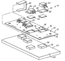
- FIG. 1 is an illustration of an embodiment of an electronics assembly with a thermal dissipation configuration in accordance with the present invention, the electronics assembly illustrated in an exploded view;
- FIG. 2 is a top view of an embodiment of an electronics assembly with a thermal dissipation configuration in accordance with the present invention.
- FIG. 3 is a cross-sectional illustration of the electronics assembly illustrated in FIG. 2, the cross-section taken along lines 3 — 3 in the direction of the arrows;
- the electronics assembly 10 includes a substrate 12 .
- the substrate 12 is intended to be a standard circuit board, although a variety of substrates are known in the prior art and contemplated by the present invention.
- the substrate 12 has a first side 14 and a second side 16 .
- At least one opening 18 is formed in the substrate 12 .
- the electronics assembly further includes a power device 20 mounted on the first side 14 of the substrate 12 .
- the at least one power device 20 is mounted on the substrate 12 in a position directly over the at least one opening 18 .
- a heatsink element 22 may be positioned on the second side 16 of the substrate 12 and yet can remain in thermal communication with the power device 20 through the at least one opening 18 .
- the present invention provides thermal transfer from the power device 20 to heatsink 22 while reducing clamping forces experienced by the power device 20 or the substrate 12 .
- the at least one opening 18 in the substrate 12 allows the power device 20 to be placed in secured communication with the heatsink element 22 without the prior art detriments of either the power device 20 being pressed into the substrate 12 or the heatsink 22 being pressed into the substrate 12 .
- thermal dissipation from the power device 20 into the heatsink 22 is not limited by having to physically pass through the material of the substrate 12 . In this way, greater thermal dissipation may be accomplished without damage to the substrate 12 or neighboring components (not shown) mounted on the substrate 12 .
- the heatsink element 22 includes a base portion 24 and at least one elevated portion 26 .
- the at least one elevated portion 26 is placed in close communication with the at least one opening 18 to provide a thermal dissipation surface 28 for thermal communication with the power device 20 .
- the present invention may further include an insulator element 30 positioned between the thermal communication surface 28 and the power device 20 to help prevent electrical shorting of the power device 20 .
- the insulator element 30 is anodized aluminum.
- the present invention may be further improved by including at least one conductive strap element 32 positioned in electrical communication with the power device 20 .
- the conductive strap element 32 may be attached to the power device 20 in a variety of fashions, in one embodiment the conductive strap element 32 is mounted to the power device 20 using a high temperature solder.
- the substrate 12 may further include at least one solder pad 36 .
- the electrically conductive strap element 32 may be attached to the power device 20 in a variety of fashions, a high temperature connection is established using high temperature solder or high temperature electrical adhesive.
- the power device 20 and the electrically conductive strap element 32 may be preassembled into a power assembly 40 prior to attachment to the substrate 12 .
- the high temperature connection allows the power assembly 40 , and specifically the electrically conductive strap 32 , to be attached to the solder pads 36 using conventional and low cost operation such as reflow soldering.
- this configuration can also use the electrically conductive strap 32 to transfer high current signals from the power device 20 into the substrate 12 . In this fashion, power devices 20 with high current output may be used with the electronics assembly 10 .
- the electrically conductive strap element 32 may be formed with at least one stress absorbing element 42 such as the arc illustrated.
- the stress absorbing element 42 allows some vertical travel of the power device 20 such that the heatsink 22 may be pressed firmly into thermal communication with the electrically conductive strap element 32 without creating unnecessary stress on the power device 20 or the substrate 12 . This provides further assurances of adequate thermal contact and communication while further reducing stresses on components within the electronic assembly 10 .
- a clamping element 44 is used to press the power device 20 into thermal communication with the heatsink 22 , the stress reducing elements 42 can permit such movement without the clamping forces being translated into the substrate 12 or causing electrical shorts within the substrate. It should be understood that while one particular clamping element 44 has been illustrated, a wide variety of clamping elements are known and contemplated by the present invention.
Landscapes
- Engineering & Computer Science (AREA)
- Microelectronics & Electronic Packaging (AREA)
- Physics & Mathematics (AREA)
- Thermal Sciences (AREA)
- Cooling Or The Like Of Semiconductors Or Solid State Devices (AREA)
- Cooling Or The Like Of Electrical Apparatus (AREA)
- Structures For Mounting Electric Components On Printed Circuit Boards (AREA)
Priority Applications (3)
| Application Number | Priority Date | Filing Date | Title |
|---|---|---|---|
| US10/099,787 US6657866B2 (en) | 2002-03-15 | 2002-03-15 | Electronics assembly with improved heatsink configuration |
| DE60331272T DE60331272D1 (de) | 2002-03-15 | 2003-02-28 | Elektronische Anordnung mit verbesserter Wärmesenke |
| EP03075591A EP1345265B1 (de) | 2002-03-15 | 2003-02-28 | Elektronische Anordnung mit verbesserter Wärmesenke |
Applications Claiming Priority (1)
| Application Number | Priority Date | Filing Date | Title |
|---|---|---|---|
| US10/099,787 US6657866B2 (en) | 2002-03-15 | 2002-03-15 | Electronics assembly with improved heatsink configuration |
Publications (2)
| Publication Number | Publication Date |
|---|---|
| US20030174469A1 US20030174469A1 (en) | 2003-09-18 |
| US6657866B2 true US6657866B2 (en) | 2003-12-02 |
Family
ID=27765455
Family Applications (1)
| Application Number | Title | Priority Date | Filing Date |
|---|---|---|---|
| US10/099,787 Expired - Lifetime US6657866B2 (en) | 2002-03-15 | 2002-03-15 | Electronics assembly with improved heatsink configuration |
Country Status (3)
| Country | Link |
|---|---|
| US (1) | US6657866B2 (de) |
| EP (1) | EP1345265B1 (de) |
| DE (1) | DE60331272D1 (de) |
Cited By (9)
| Publication number | Priority date | Publication date | Assignee | Title |
|---|---|---|---|---|
| US20030210524A1 (en) * | 2002-03-13 | 2003-11-13 | Henry Berg | Computer assembly for facilitating heat dissipation |
| US20070206361A1 (en) * | 2006-03-02 | 2007-09-06 | Cheng Sun-Wen C | System for cooling electronic components |
| US20080253090A1 (en) * | 2005-10-18 | 2008-10-16 | Vdo Automotive Ag | Ic Component Comprising a Cooling Arrangement |
| US20080278918A1 (en) * | 2007-05-07 | 2008-11-13 | Mitsubishi Electric Corporation | Electronic control apparatus |
| US20100226097A1 (en) * | 2007-12-17 | 2010-09-09 | Lynch Thomas W | Double bonded heat dissipation |
| US20100309635A1 (en) * | 2007-02-15 | 2010-12-09 | Junichi Sasaki | Structure for mounting semiconductor package |
| US20110189867A1 (en) * | 2008-06-10 | 2011-08-04 | Molex Incorporated | Elastic-cushioned capacitively-coupled connector |
| US9004925B2 (en) | 2009-01-30 | 2015-04-14 | Molex Incorporated | Capacitively coupled connector using liquid dielectric for improved performance |
| US20210337654A1 (en) * | 2019-11-26 | 2021-10-28 | Eridan Communications, Inc. | Integrated Circuit / Printed Circuit Board Assembly and Method of Manufacture |
Families Citing this family (11)
| Publication number | Priority date | Publication date | Assignee | Title |
|---|---|---|---|---|
| US7082034B2 (en) * | 2004-04-01 | 2006-07-25 | Bose Corporation | Circuit cooling |
| DE102004046475A1 (de) * | 2004-09-23 | 2006-04-13 | Sew-Eurodrive Gmbh & Co. Kg | Elektrogerät |
| DE102005014413A1 (de) * | 2005-03-24 | 2006-09-28 | Conti Temic Microelectronic Gmbh | Anordnung zur Wärmeableitung |
| DE102005039374A1 (de) * | 2005-08-19 | 2007-02-22 | BSH Bosch und Siemens Hausgeräte GmbH | Gehäuse für Elektronikbaugruppen |
| DE102006009812B4 (de) * | 2006-03-01 | 2008-09-04 | Beru Ag | Montageanordnung für mehrere Leistungshalbleiter und Schaltung mit einer solchen Montageanordnung |
| DE102010013334A1 (de) * | 2010-03-30 | 2012-05-10 | Borgwarner Beru Systems Gmbh | Leiterplatte mit Bauelement und Verfahren zum Bestücken einer Leiterplatte |
| DE102010035169A1 (de) * | 2010-08-23 | 2012-02-23 | Marquardt Verwaltungs-Gmbh | Elektrischer Schalter für Elektrohandwerkzeuge |
| US9049811B2 (en) | 2012-11-29 | 2015-06-02 | Bose Corporation | Circuit cooling |
| US9433074B2 (en) * | 2013-04-29 | 2016-08-30 | Toyota Motor Engineering & Manufacturing North America, Inc. | Printed wiring boards having thermal management features and thermal management apparatuses comprising the same |
| US10028413B2 (en) | 2014-07-25 | 2018-07-17 | Toyota Motor Engineering & Manufacturing North America, Inc. | Heat transfer management apparatuses having a composite lamina |
| JP6287815B2 (ja) * | 2014-12-24 | 2018-03-07 | 株式会社オートネットワーク技術研究所 | 回路構成体の製造方法 |
Citations (10)
| Publication number | Priority date | Publication date | Assignee | Title |
|---|---|---|---|---|
| US4647126A (en) * | 1985-06-17 | 1987-03-03 | Sperry Corporation | Compliant lead clip |
| US5317479A (en) * | 1991-09-30 | 1994-05-31 | Computing Devices International, Inc. | Plated compliant lead |
| US5379187A (en) * | 1993-03-25 | 1995-01-03 | Vlsi Technology, Inc. | Design for encapsulation of thermally enhanced integrated circuits |
| US5596231A (en) * | 1991-08-05 | 1997-01-21 | Asat, Limited | High power dissipation plastic encapsulated package for integrated circuit die |
| US5650914A (en) * | 1994-11-18 | 1997-07-22 | Tessera, Inc. | Compliant thermal connectors, methods of making the same and assemblies incorporating the same |
| US5787576A (en) * | 1995-07-31 | 1998-08-04 | Borg-Warner Automotive, Inc. | Method for dissipating heat from an integrated circuit |
| US5856911A (en) * | 1996-11-12 | 1999-01-05 | National Semiconductor Corporation | Attachment assembly for integrated circuits |
| US5920458A (en) * | 1997-05-28 | 1999-07-06 | Lucent Technologies Inc. | Enhanced cooling of a heat dissipating circuit element |
| US6000125A (en) * | 1996-01-30 | 1999-12-14 | Samsung Electronics America, Inc. | Method of heat dissipation from two surfaces of a microprocessor |
| US6376907B1 (en) * | 1997-12-01 | 2002-04-23 | Kabushiki Kaisha Toshiba | Ball grid array type package for semiconductor device |
Family Cites Families (5)
| Publication number | Priority date | Publication date | Assignee | Title |
|---|---|---|---|---|
| US4563725A (en) * | 1983-01-06 | 1986-01-07 | Welwyn Electronics Limited | Electrical assembly |
| US5812375A (en) * | 1996-05-06 | 1998-09-22 | Cummins Engine Company, Inc. | Electronic assembly for selective heat sinking and two-sided component attachment |
| SE9702593D0 (sv) * | 1997-07-04 | 1997-07-04 | Electrolux Ab | Anordning vid ett kretskort |
| FR2777734B1 (fr) * | 1998-04-15 | 2004-07-09 | Sagem | Ensemble d'une carte de circuit imprime a composants de puissance et d'un radiateur pour la carte |
| DE19830576A1 (de) * | 1998-07-08 | 2000-01-13 | Iro Patent Ag Baar | Fadenbearbeitungssystem |
-
2002
- 2002-03-15 US US10/099,787 patent/US6657866B2/en not_active Expired - Lifetime
-
2003
- 2003-02-28 DE DE60331272T patent/DE60331272D1/de not_active Expired - Lifetime
- 2003-02-28 EP EP03075591A patent/EP1345265B1/de not_active Expired - Lifetime
Patent Citations (10)
| Publication number | Priority date | Publication date | Assignee | Title |
|---|---|---|---|---|
| US4647126A (en) * | 1985-06-17 | 1987-03-03 | Sperry Corporation | Compliant lead clip |
| US5596231A (en) * | 1991-08-05 | 1997-01-21 | Asat, Limited | High power dissipation plastic encapsulated package for integrated circuit die |
| US5317479A (en) * | 1991-09-30 | 1994-05-31 | Computing Devices International, Inc. | Plated compliant lead |
| US5379187A (en) * | 1993-03-25 | 1995-01-03 | Vlsi Technology, Inc. | Design for encapsulation of thermally enhanced integrated circuits |
| US5650914A (en) * | 1994-11-18 | 1997-07-22 | Tessera, Inc. | Compliant thermal connectors, methods of making the same and assemblies incorporating the same |
| US5787576A (en) * | 1995-07-31 | 1998-08-04 | Borg-Warner Automotive, Inc. | Method for dissipating heat from an integrated circuit |
| US6000125A (en) * | 1996-01-30 | 1999-12-14 | Samsung Electronics America, Inc. | Method of heat dissipation from two surfaces of a microprocessor |
| US5856911A (en) * | 1996-11-12 | 1999-01-05 | National Semiconductor Corporation | Attachment assembly for integrated circuits |
| US5920458A (en) * | 1997-05-28 | 1999-07-06 | Lucent Technologies Inc. | Enhanced cooling of a heat dissipating circuit element |
| US6376907B1 (en) * | 1997-12-01 | 2002-04-23 | Kabushiki Kaisha Toshiba | Ball grid array type package for semiconductor device |
Cited By (15)
| Publication number | Priority date | Publication date | Assignee | Title |
|---|---|---|---|---|
| US20030210524A1 (en) * | 2002-03-13 | 2003-11-13 | Henry Berg | Computer assembly for facilitating heat dissipation |
| US20080253090A1 (en) * | 2005-10-18 | 2008-10-16 | Vdo Automotive Ag | Ic Component Comprising a Cooling Arrangement |
| US20070206361A1 (en) * | 2006-03-02 | 2007-09-06 | Cheng Sun-Wen C | System for cooling electronic components |
| US7450387B2 (en) * | 2006-03-02 | 2008-11-11 | Tdk Innoveta Technologies, Inc. | System for cooling electronic components |
| US7983048B2 (en) * | 2007-02-15 | 2011-07-19 | Nec Corporation | Structure for mounting semiconductor package |
| US20100309635A1 (en) * | 2007-02-15 | 2010-12-09 | Junichi Sasaki | Structure for mounting semiconductor package |
| US20080278918A1 (en) * | 2007-05-07 | 2008-11-13 | Mitsubishi Electric Corporation | Electronic control apparatus |
| US7643297B2 (en) * | 2007-05-07 | 2010-01-05 | Mitsubishi Electric Corporation | Electronic control apparatus |
| US20100226097A1 (en) * | 2007-12-17 | 2010-09-09 | Lynch Thomas W | Double bonded heat dissipation |
| US8018722B2 (en) * | 2007-12-17 | 2011-09-13 | Tanima Holdings, Llc | Double bonded heat dissipation |
| US20110189867A1 (en) * | 2008-06-10 | 2011-08-04 | Molex Incorporated | Elastic-cushioned capacitively-coupled connector |
| US8287289B2 (en) * | 2008-06-10 | 2012-10-16 | Molex Incorporated | Elastic-cushioned capacitively-coupled connector |
| US9004925B2 (en) | 2009-01-30 | 2015-04-14 | Molex Incorporated | Capacitively coupled connector using liquid dielectric for improved performance |
| US20210337654A1 (en) * | 2019-11-26 | 2021-10-28 | Eridan Communications, Inc. | Integrated Circuit / Printed Circuit Board Assembly and Method of Manufacture |
| US11910519B2 (en) * | 2019-11-26 | 2024-02-20 | Eridan Communications, Inc. | Integrated circuit / printed circuit board assembly and method of manufacture |
Also Published As
| Publication number | Publication date |
|---|---|
| US20030174469A1 (en) | 2003-09-18 |
| EP1345265B1 (de) | 2010-02-17 |
| EP1345265A2 (de) | 2003-09-17 |
| EP1345265A3 (de) | 2005-05-11 |
| DE60331272D1 (de) | 2010-04-01 |
Similar Documents
| Publication | Publication Date | Title |
|---|---|---|
| US6657866B2 (en) | Electronics assembly with improved heatsink configuration | |
| CN100394602C (zh) | 电子线路装置及其制造方法 | |
| US7557442B2 (en) | Power semiconductor arrangement | |
| US5473511A (en) | Printed circuit board with high heat dissipation | |
| CN102017135B (zh) | 带有在多个接触平面中的元器件的基板电路模块 | |
| JPH11330750A (ja) | 伝熱経路の形成方法および伝熱経路装置 | |
| CN110431664A (zh) | 将led元件安装在平的载体上 | |
| JP2011108924A (ja) | 熱伝導基板及びその電子部品実装方法 | |
| US6188579B1 (en) | Apparatus and methods for forming a printed wiring board assembly to reduce pallet warpage | |
| JP3603354B2 (ja) | 混成集積回路装置 | |
| US7049171B2 (en) | Electrical package employing segmented connector and solder joint | |
| JP6981033B2 (ja) | 半導体装置及び半導体装置の製造方法 | |
| US6285554B1 (en) | Method and an arrangement for the electrical contact of components | |
| JP2001168476A (ja) | 回路基板上での放熱構造 | |
| US6858807B2 (en) | Substrate for receiving a circuit configuration and method for producing the substrate | |
| JPH05259669A (ja) | 印刷配線基板の放熱構造 | |
| JP2020202329A (ja) | 電子制御装置 | |
| US20050167696A1 (en) | Silicon nitride insulating substrate for power semiconductor module | |
| JPH0529502A (ja) | プリント基板 | |
| JPH0320067A (ja) | セラミック放熱フィン付半導体装置 | |
| WO2000069236A1 (en) | A thermally enhanced via/bga microwave circuit ceramic package | |
| JP2022057425A (ja) | パワーモジュール及びパワーモジュールの製造方法 | |
| JPH07297518A (ja) | 電子部品の実装構造 | |
| JP4961215B2 (ja) | パワーデバイス装置 | |
| US6118660A (en) | Circuit module with improved heat transfer |
Legal Events
| Date | Code | Title | Description |
|---|---|---|---|
| AS | Assignment |
Owner name: DELPHI TECHNOLOGIES, INC., MICHIGAN Free format text: ASSIGNMENT OF ASSIGNORS INTEREST;ASSIGNOR:MORELOCK, ROBERT C.;REEL/FRAME:012715/0306 Effective date: 20020315 |
|
| STCF | Information on status: patent grant |
Free format text: PATENTED CASE |
|
| FPAY | Fee payment |
Year of fee payment: 4 |
|
| FPAY | Fee payment |
Year of fee payment: 8 |
|
| FPAY | Fee payment |
Year of fee payment: 12 |
|
| AS | Assignment |
Owner name: DELPHI TECHNOLOGIES IP LIMITED, BARBADOS Free format text: ASSIGNMENT OF ASSIGNORS INTEREST;ASSIGNOR:DELPHI TECHNOLOGIES, INC.;REEL/FRAME:045109/0063 Effective date: 20171129 |