US6681166B2 - Steer-by-wire drive control system with operating element home position updating function - Google Patents
Steer-by-wire drive control system with operating element home position updating function Download PDFInfo
- Publication number
- US6681166B2 US6681166B2 US10/191,130 US19113002A US6681166B2 US 6681166 B2 US6681166 B2 US 6681166B2 US 19113002 A US19113002 A US 19113002A US 6681166 B2 US6681166 B2 US 6681166B2
- Authority
- US
- United States
- Prior art keywords
- home position
- operating element
- steering
- controller
- steering wheel
- Prior art date
- Legal status (The legal status is an assumption and is not a legal conclusion. Google has not performed a legal analysis and makes no representation as to the accuracy of the status listed.)
- Expired - Fee Related
Links
- 230000006866 deterioration Effects 0.000 description 6
- 238000001514 detection method Methods 0.000 description 4
- 230000001788 irregular Effects 0.000 description 4
- 238000000034 method Methods 0.000 description 1
Images




Classifications
-
- B—PERFORMING OPERATIONS; TRANSPORTING
- B62—LAND VEHICLES FOR TRAVELLING OTHERWISE THAN ON RAILS
- B62D—MOTOR VEHICLES; TRAILERS
- B62D5/00—Power-assisted or power-driven steering
- B62D5/001—Mechanical components or aspects of steer-by-wire systems, not otherwise provided for in this maingroup
- B62D5/005—Mechanical components or aspects of steer-by-wire systems, not otherwise provided for in this maingroup means for generating torque on steering wheel or input member, e.g. feedback
- B62D5/006—Mechanical components or aspects of steer-by-wire systems, not otherwise provided for in this maingroup means for generating torque on steering wheel or input member, e.g. feedback power actuated
-
- B—PERFORMING OPERATIONS; TRANSPORTING
- B62—LAND VEHICLES FOR TRAVELLING OTHERWISE THAN ON RAILS
- B62D—MOTOR VEHICLES; TRAILERS
- B62D15/00—Steering not otherwise provided for
- B62D15/02—Steering position indicators ; Steering position determination; Steering aids
- B62D15/021—Determination of steering angle
- B62D15/0245—Means or methods for determination of the central position of the steering system, e.g. straight ahead position
-
- B—PERFORMING OPERATIONS; TRANSPORTING
- B62—LAND VEHICLES FOR TRAVELLING OTHERWISE THAN ON RAILS
- B62D—MOTOR VEHICLES; TRAILERS
- B62D6/00—Arrangements for automatically controlling steering depending on driving conditions sensed and responded to, e.g. control circuits
- B62D6/008—Control of feed-back to the steering input member, e.g. simulating road feel in steer-by-wire applications
Definitions
- the present invention relates to a steer-by-wire drive control system such as a steer-by-wire steering device built in a vehicle and particularly to means for updating the home position of an operating element.
- FIG. 5 shows the structure of a conventional steer-by-wire steering device
- FIG. 6 is a graph showing the relation between an external force applied to the tire and a reactive force applied to the steering wheel.
- this steer-by-wire steering device comprises: a steering wheel 1 as an operating element; an operating angle sensor 2 which senses the operating condition of the steering wheel 1 ; an operating element actuator 3 as a force feedback actuator which applies an external force for force feedback to the steering wheel 1 ; a tire reactive force sensor 5 for sensing the reactive force from a road surface which acts on a vehicle's steering system 4 as an operated device; a steering actuator 6 as an actuator for driving the operated device which applies an external force for steering to the steering system 4 ; a first controller 7 (CPU) which receives output signals a and f from the operating angle sensor 2 and the steering system 4 respectively and controls the operating element actuator 3 ; and a second controller 9 which receives output from the tire reactive force sensor 5 and a signal b for information on the operating condition of the steering wheel 1 and controls operation of the steering actuator 6 .
- a steering wheel 1 as an operating element
- an operating element actuator 3 as a force feedback actuator which applies an external force for force feedback to the steering wheel 1
- the steering wheel 1 is designed to be able to be turned clockwise and counterclockwise.
- the steering system 4 of the vehicle is designed to be able to move the tires 8 to the right and the left by the same amount from the home position of the system.
- the home position of the steering wheel 1 for force feedback control is adjusted with reference to the home position of the steering system 4 of the vehicle so that the vehicle can go straight ahead on a flat road surface.
- the operating direction and angle of the steering wheel are detected by the operating angle sensor 2 , which in turn outputs a steering signal a depending on the operating direction and angle of the steering wheel 1 .
- the first controller 7 receives this steering signal a and generates and outputs an information signal b for indicating the operating condition of the steering wheel 1 , which depends on the signal a.
- This information signal b drives the steering actuator 6 to laterally move the vehicle's steering system 4 in the direction corresponding to the operating direction of the steering wheel 1 , by the angle of rotation equivalent to the operating angle of the steering wheel 1 , so that the vehicle curves to the right or left.
- a reactive force (cornering force) from the road surface which depends on the vehicle's speed, steering angle and other factors acts on the tires 8 and the tire reactive force sensor 5 outputs a tire reactive force detection signal c which depends on the reactive force.
- the second controller 9 receives the tire reactive force detection signal c and outputs a control signal f.
- the first controller 7 receives the control signal f and generates and outputs a drive signal d for the operating element actuator 3 which depends on the signal f.
- This drive signal d drives the operating element actuator 3 and, as shown in FIG. 6, an external force proportional to the reactive force which acts on the tires 8 is given to the steering wheel 1 . In this way, the driver can get the same kind of driving feeling as when he or she drives a vehicle with a mechanical steering device.
- the home position of the steering wheel 1 for force feedback control may become out of alignment with the home position of the steering system 4 built in the vehicle because of irregular tire wear or irregular wear of a steering system mechanical component.
- the home position of the steering wheel 1 for force feedback control deviates from the home position of the steering system 4 built in the vehicle, when the steering wheel 1 is held in its home position, the vehicle would curve in the direction opposite to the deviation; on the other hand, when the steering wheel 1 is operated in a manner to suit the running condition of the vehicle, the steering wheel 1 should be off its home position, or on the deviation side, the driving feeling would worsen and also, even if the steering wheel 1 is turned by the same angle of rotation clockwise and counterclockwise, the vehicle would not curve by the same angle of rotation clockwise and counterclockwise, impairing the vehicle's driving safety and operability.
- the conventional type of steer-by-wire steering device has no means to automatically compensate for a discrepancy between the home position of the steering wheel 1 for force feedback control and the home position of the steering system 4 and, therefore, cannot prevent the above-mentioned inconvenience.
- the present invention has been made to solve the above problem inherent to the prior art and provides a steer-by-wire drive control system with a high operability and a high durability which automatically compensates for a discrepancy between the home position of the steering wheel for force feedback control and the home position of the steering system built in the vehicle.
- a steer-by-wire drive control system which comprises: an operating element which can be operated in a first direction and a second direction; a sensor which detects an operating condition of the operating element; an operating element actuator which applies an external force to the operating element; and a controller which controls operation of the operating element actuator with reference to a memorized home position, wherein the controller calculates frequencies of a signal outputted from the sensor and updates the operating element's home position memorized in the controller to the operating element's position where the signal is most frequently outputted, as a new home position of the operating element.
- the steering wheel is operated with reference to the home position of the steering system (operated device) regardless of the home position of the steering wheel (operating element) for force feedback control in order to let the vehicle run along a desired course.
- the driver controls the steering wheel with reference to a position deviated from its home position instead of with reference to the home position of the steering wheel.
- the steering wheel operating angle corresponding to the steering system's home position is most frequently used and the larger the steering wheel operating angle is, the less frequently it is used.
- the controller since the controller repeatedly calculates frequencies of signals outputted from the steering wheel operating angle sensor to get information on the current actual home position of the steering wheel, the steering wheel operating angle (position) where the signal is most frequently outputted is re-memorized in the controller as a new home position of the steering wheel to make the steering wheel's home position for force feedback control agree with the steering system's home position.
- operation of the operating element actuator force feedback actuator
- the controller updates the operating element's home position memorized in the controller when a difference between the operating element's home position memorized in the controller and the calculated new home position reaches a prescribed value.
- An advantage of this arrangement is that the operability and driving safety are improved because the operating element's home position is updated before the driver begins to feel deterioration in the vehicle's operability.
- a steer-by-wire drive control system comprises: an operating element which can be operated in a first direction and a second direction; a first sensor which detects an operating condition of the operating element; an operating element actuator which applies an external force to the operating element; an operated device which is operated in a first direction and a second direction from a home position by controlling the operating element; a second sensor which detects a condition of the operated device; an operated device actuator which drives the operated device; a first controller which controls operation of the operating element actuator with reference to a memorized home position of the operating element; and a second controller which receives information on the operating condition of the operating element from the first controller and controls operation of the operated device actuator, wherein the first controller receives a signal outputted from the second sensor to detect a home position of the operated device and updates the operating element's home position memorized in the first controller with reference to the home position of the operated device.
- the steering wheel is operated with reference to the home position of the steering system (operated device) regardless of the home position of the steering wheel (operating element) for force feedback control.
- the steering wheel operating angle (position) corresponding to the steering system's home position is re-memorized in the controller as a new home position of the steering wheel so that the steering wheel's home position agrees with the steering system's home position.
- the first controller updates the operating element's home position memorized in the first controller when a difference between the operating element's home position memorized in the first controller and the operated device's home position reaches a prescribed value.
- An advantage of this arrangement is that the operability and driving safety are improved because the operating element's home position is updated before the driver begins to feel deterioration in the vehicle's operability.
- FIG. 1 shows the structure of a steer-by-wire drive control system according to a first embodiment of the present invention
- FIG. 2 is a graph showing the relation between the steering wheel operating angle and the steering wheel operation frequency
- FIG. 3 shows the structure of a steer-by-wire drive control system according to a second embodiment of the present invention
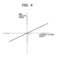
- FIG. 4 is a graph showing the relation between the steering angle of the steering system built in the vehicle and the tire reactive force
- FIG. 5 shows the structure of a conventional steer-by-wire drive control system
- FIG. 6 is a graph showing the relation between the external force applied to the steering wheel and the external force applied to the vehicle's tire in the conventional steer-by-wire drive control system.
- FIG. 1 shows the structure of a steer-by-wire drive control system according to the first embodiment of the present invention
- FIG. 2 is a graph showing the relation between the steering wheel operating angle and the steering wheel operation frequency.
- the steer-by-wire steering device has the same basic structure as the conventional steer-by-wire steering device as shown in FIG. 5 .
- This steer-by-wire steering device comprises: a steering wheel 1 (operating element); an operating angle sensor 2 which senses the operating condition of the steering wheel 1 ; an operating element actuator 3 (force feedback actuator) which applies an external force for force feedback control to the steering wheel 1 ; a tire reactive force sensor 5 which senses the reactive force from the road surface which acts on the vehicle's steering system 4 (operated device); a steering actuator 6 (actuator for driving the operated device) which applies an external force for steering to the steering system 4 ; a first controller 7 (CPU) which receives an output signal a from the operating angle sensor 2 and a control signal f depending on the condition of the steering system 4 and outputs a drive signal d for the operating element actuator 3 ; and a second controller 9 which receives a signal b for information on the operating condition of the steering wheel 1 from the first controller 7 , receives
- a steering wheel 1
- the first controller 7 comprises: a home position memory 7 a which memorizes the home position of the steering wheel 1 for force feedback control; a frequency calculating section 7 b which receives a steering signal a from the operating angle sensor 2 and calculates the operating angle of the steering wheel 1 with reference to the home position information memorized in the home position memory 7 a and the frequency of input of the steering signal a for each operating angle; and a home position rewriting section 7 c which memorizes the operating angle of the steering wheel 1 corresponding to the highest frequency of input of the steering signal a, as a new home position of the steering wheel 1 in the home position memory 7 a .
- the home position memorized in the home position memory 7 a is repeatedly rewritten.
- This home position rewriting operation may be done at regular intervals or at irregular intervals. If the rewriting operation is to be done at irregular intervals, for example, rewriting may take place each time the difference between the home position memorized in the home position memory 7 a and the current home position calculated by the frequency calculating section 7 b reaches a predetermined value.
- the initially memorized home position is determined with reference to the home position of the vehicle's steering system 4 so that the vehicle runs straight on a flat road surface.
- the operating angle of the steering wheel 1 corresponding to the home position of the steering system 4 is most frequently used; and the larger the steering wheel's 1 operating angle is, the less frequently it is used.
- the frequency of input of the steering signal a is the highest at an operating angle of 0 degree, as indicated by the solid line in FIG. 2 .
- the driver controls the steering wheel 1 with reference to the home position of the steering system 4 in his/her attempt to let the vehicle run along the desired course.
- the most frequently used operating angle of the steering wheel 1 deviates from the home position of the steering wheel 1 by the angle of rotation corresponding to the difference between the home position of the steering wheel 1 and that of the steering system 4 , as indicated by the dotted line in FIG. 2 .
- the controller 7 receives a steering signal a outputted from the operating angle sensor 2 to get information on the current actual home position of the steering wheel 1
- the home position memorized in the home position memory 7 a is rewritten to the current actual home position by the home position rewriting section 7 c to compensate for a discrepancy between the home position of the steering wheel 1 for force feedback control and the home position of the steering system 4 .
- the steering signal a outputted from the operating angle sensor 2 matches the actual operating direction and angle of the steering wheel 1 , and also signals b and d, which are generated based on the steering signal a, match the actual operating direction and angle of the steering wheel 1 .
- FIG. 3 shows the structure of a steer-by-wire steering device according to this embodiment of the present invention.
- FIG. 4 is a graph showing the relation between the steering angle of the steering system built in the vehicle and the tire reactive force.
- the steer-by-wire steering device has the same basic structure as the steer-by-wire steering device according to the first embodiment shown in FIG. 1 .
- This steer-by-wire steering device comprises: a steering wheel 1 (operating element); an operating angle sensor (first sensor) 2 which senses the operating condition of the steering wheel 1 ; an operating element actuator (force feedback actuator) 3 which applies an external force for force feedback control to the steering wheel 1 ; a tire reactive force sensor (second sensor) 5 which senses the reactive force from the road surface which acts on the vehicle's steering system (operated device) 4 ; a steering actuator (actuator for driving the operated device) 6 which drives the steering system 4 ; a first controller 7 which receives an output signal a from the operating angle sensor 2 and operating element actuator 3 ; and a second controller 9 which receives a signal b for a control signal f from the steering system 4 and outputs a signal d for driving the information on the operating condition of the steering wheel 1 from the first controller 7 , receives
- the first controller 7 comprises: a home position memory 7 a which memorizes the home position of the steering wheel 1 for force feedback control; a home position calculating section 7 d which receives a tire reactive force detection signal c from the tire reactive force sensor (second sensor) 5 to calculate the home position of the steering system (operated device) 4 of the vehicle; and a home position rewriting section 7 c which memorizes the home position calculated by the home position calculating section 7 d as a new home position of the steering wheel 1 for force feedback control in the home position memory 7 a .
- a rewriting signal from the home position rewriting section 7 c the home position memorized in the home position memory 7 a is repeatedly rewritten. This home position rewriting operation may be done at regular intervals or at odd intervals.
- the initially memorized home position is determined with reference to the home position of the vehicle's steering system 4 so that the vehicle runs straight on a flat road surface.
- the reactive force from the road surface which acts on the tires during driving is zero while the vehicle is running straight, namely when the vehicle's steering system 4 is in its home position, and increases as the turning angle of the steering wheel 4 increases.
- the controller 7 receives a tire reactive force detection signal c from the tire reactive force sensor (second sensor) 5 to get information on the current actual home position of the steering wheel 4 , the home position memorized in the home position memory 7 a is rewritten to the current actual home position by the home position rewriting section 7 c to compensate for a discrepancy between the home position of the steering wheel 1 for force feedback control and the home position of the steering system 4 .
- the steering signal a outputted from the operating angle sensor 2 matches the actual operating direction and angle of the steering wheel 1 , and also signals b and d, which are generated based on the steering signal a, match the actual operating direction and angle of the steering wheel 1 .
- a steer-by-wire drive control system may be embodied not only for a steering device but also for any device incorporating an operating element which can be operated in a first direction and a second direction and an operated device which can be operated in a first direction and a second direction from its home position.
- the steering wheel 1 is used as an operating element; however, the invention may be embodied in the form of a steer-by-wire drive control system which uses a laterally movable lever as an operating element
- the frequencies of signal outputs from a sensor which detects the operating condition (position) of an operating element are repeatedly calculated by a controller and the home position of the operating element is updated by memorizing the operating element's position where the signal is most frequently outputted as a new home position of the operating element, so that a discrepancy between the home position of the operating element and the home position of the operated device can be automatically eliminated and the operability and safety of the steer-by-wire drive control system can be improved.
- a controller receives a signal from a sensor which detects the condition of the operated device to calculate the home position of the operated device, and if there is a discrepancy between the home position of the operating element for force feedback control and the home position of the operated device, the home position of the operating element is adjusted with reference to the home position of the operated device so that the discrepancy between the home position of the operating element and the home position of the operated device can be automatically eliminated and the operability and safety of the steer-by-wire drive control system can be improved.
Landscapes
- Engineering & Computer Science (AREA)
- Chemical & Material Sciences (AREA)
- Combustion & Propulsion (AREA)
- Transportation (AREA)
- Mechanical Engineering (AREA)
- Steering Control In Accordance With Driving Conditions (AREA)
- Power Steering Mechanism (AREA)
Applications Claiming Priority (2)
| Application Number | Priority Date | Filing Date | Title |
|---|---|---|---|
| JP2001210928A JP2003026021A (ja) | 2001-07-11 | 2001-07-11 | バイワイヤ方式の駆動制御装置 |
| JP2001-210928 | 2001-07-11 |
Publications (2)
| Publication Number | Publication Date |
|---|---|
| US20030014169A1 US20030014169A1 (en) | 2003-01-16 |
| US6681166B2 true US6681166B2 (en) | 2004-01-20 |
Family
ID=19046327
Family Applications (1)
| Application Number | Title | Priority Date | Filing Date |
|---|---|---|---|
| US10/191,130 Expired - Fee Related US6681166B2 (en) | 2001-07-11 | 2002-07-09 | Steer-by-wire drive control system with operating element home position updating function |
Country Status (4)
| Country | Link |
|---|---|
| US (1) | US6681166B2 (fr) |
| EP (1) | EP1277646B1 (fr) |
| JP (1) | JP2003026021A (fr) |
| DE (1) | DE60201478T2 (fr) |
Cited By (6)
| Publication number | Priority date | Publication date | Assignee | Title |
|---|---|---|---|---|
| US20030229430A1 (en) * | 2002-06-11 | 2003-12-11 | Sauer-Danfoss (Nordborg) A/S | Vehicle steering system and method of steering |
| US20060200291A1 (en) * | 2005-03-07 | 2006-09-07 | Wroblewski Anthony J | Tactile electronic steering system |
| US20060200290A1 (en) * | 2005-03-01 | 2006-09-07 | Naotaka Chino | Steering control apparatus |
| US20060200289A1 (en) * | 2005-03-01 | 2006-09-07 | Naotaka Chino | Steering control system |
| US20100031739A1 (en) * | 2008-08-08 | 2010-02-11 | Gm Global Technology Opearations, Inc. | Method of measuring torsional dynamics of a steering column at small dynamic amplitudes |
| US10035537B2 (en) * | 2006-07-07 | 2018-07-31 | Hydro-Gear Limited Partnership | Front steering module for a zero turn radius vehicle |
Families Citing this family (13)
| Publication number | Priority date | Publication date | Assignee | Title |
|---|---|---|---|---|
| US7100733B2 (en) | 2002-07-22 | 2006-09-05 | Visteon Global Technologies, Inc. | Method to initialize steering wheel in a steer-by-wire system |
| JP4100130B2 (ja) * | 2002-10-31 | 2008-06-11 | 株式会社ジェイテクト | 車両用操舵装置 |
| US6732979B1 (en) | 2003-08-28 | 2004-05-11 | The Boeing Company | Steer-by-wire tiller with position feel system |
| JP4604991B2 (ja) * | 2005-12-07 | 2011-01-05 | トヨタ自動車株式会社 | 車両の操舵装置 |
| FR2929222A1 (fr) * | 2008-03-28 | 2009-10-02 | Renault Sas | Procede et dispositif d'adaptation a l'usure d'un vehicule d'au moins un parametre de commande d'un dispositif de restitution d'efforts au volant |
| WO2011013217A1 (fr) | 2009-07-29 | 2011-02-03 | トヨタ自動車株式会社 | Système de commande de direction |
| US8788149B2 (en) * | 2010-08-05 | 2014-07-22 | Toyota Jidosha Kabushiki Kaisha | Steering control device |
| CN102923228A (zh) | 2011-08-12 | 2013-02-13 | 斯马特脚踏车制造公司 | 三轮车及其转向轮 |
| KR101606231B1 (ko) * | 2012-07-26 | 2016-04-01 | 주식회사 만도 | 전동식 조향 장치 및 그의 제어방법 |
| DE102014206465A1 (de) | 2014-04-03 | 2015-10-08 | Volkswagen Aktiengesellschaft | Regelungsvorrichtung für eine elektromechanische Servolenkung |
| US10946894B2 (en) * | 2017-10-17 | 2021-03-16 | Steering Solution Ip Holding Corporation | Driver warning in electric power steering systems |
| JP7351691B2 (ja) * | 2019-09-26 | 2023-09-27 | 株式会社ジェイテクト | 操舵制御装置 |
| DE102019135047A1 (de) * | 2019-12-19 | 2021-06-24 | Bayerische Motoren Werke Aktiengesellschaft | Steer-by-Wire-Lenksystem, Verfahren zum Betrieb eines Steer-by-Wire-Lenksystems und Fahrzeug |
Citations (6)
| Publication number | Priority date | Publication date | Assignee | Title |
|---|---|---|---|---|
| US6097286A (en) | 1997-09-30 | 2000-08-01 | Reliance Electric Technologies, Llc | Steer by wire system with feedback |
| EP1211161A2 (fr) | 2000-11-27 | 2002-06-05 | Koyo Seiko Co., Ltd. | Capteur d'angle de direction pour véhicule automobile et direction assistée utilisant celui-ci |
| US6535806B2 (en) * | 2001-01-30 | 2003-03-18 | Delphi Technologies, Inc. | Tactile feedback control for steer-by-wire systems |
| US6554095B2 (en) * | 2001-04-06 | 2003-04-29 | Visteon Global Technologies, Inc. | Torque-based steering system for steer by wire vehicles |
| US6575263B2 (en) * | 2001-04-26 | 2003-06-10 | Eaton Corporation | Torque device for electronic steer-by wire steering systems |
| US6588540B2 (en) * | 2001-07-26 | 2003-07-08 | Delphi Technologies, Inc. | Steer-by-wire redundant handwheel control |
-
2001
- 2001-07-11 JP JP2001210928A patent/JP2003026021A/ja active Pending
-
2002
- 2002-07-09 DE DE60201478T patent/DE60201478T2/de not_active Expired - Fee Related
- 2002-07-09 EP EP02015284A patent/EP1277646B1/fr not_active Expired - Lifetime
- 2002-07-09 US US10/191,130 patent/US6681166B2/en not_active Expired - Fee Related
Patent Citations (6)
| Publication number | Priority date | Publication date | Assignee | Title |
|---|---|---|---|---|
| US6097286A (en) | 1997-09-30 | 2000-08-01 | Reliance Electric Technologies, Llc | Steer by wire system with feedback |
| EP1211161A2 (fr) | 2000-11-27 | 2002-06-05 | Koyo Seiko Co., Ltd. | Capteur d'angle de direction pour véhicule automobile et direction assistée utilisant celui-ci |
| US6535806B2 (en) * | 2001-01-30 | 2003-03-18 | Delphi Technologies, Inc. | Tactile feedback control for steer-by-wire systems |
| US6554095B2 (en) * | 2001-04-06 | 2003-04-29 | Visteon Global Technologies, Inc. | Torque-based steering system for steer by wire vehicles |
| US6575263B2 (en) * | 2001-04-26 | 2003-06-10 | Eaton Corporation | Torque device for electronic steer-by wire steering systems |
| US6588540B2 (en) * | 2001-07-26 | 2003-07-08 | Delphi Technologies, Inc. | Steer-by-wire redundant handwheel control |
Cited By (11)
| Publication number | Priority date | Publication date | Assignee | Title |
|---|---|---|---|---|
| US20030229430A1 (en) * | 2002-06-11 | 2003-12-11 | Sauer-Danfoss (Nordborg) A/S | Vehicle steering system and method of steering |
| US6912455B2 (en) * | 2002-06-11 | 2005-06-28 | Sauer-Danfoss (Nordborg) A/S | Vehicle steering system and method of steering |
| US20060200290A1 (en) * | 2005-03-01 | 2006-09-07 | Naotaka Chino | Steering control apparatus |
| US20060200289A1 (en) * | 2005-03-01 | 2006-09-07 | Naotaka Chino | Steering control system |
| US7664584B2 (en) * | 2005-03-01 | 2010-02-16 | Nissan Motor Co., Ltd. | Steering control system |
| US7698035B2 (en) * | 2005-03-01 | 2010-04-13 | Nissan Motor Co., Ltd. | Steering control apparatus |
| US20060200291A1 (en) * | 2005-03-07 | 2006-09-07 | Wroblewski Anthony J | Tactile electronic steering system |
| US10035537B2 (en) * | 2006-07-07 | 2018-07-31 | Hydro-Gear Limited Partnership | Front steering module for a zero turn radius vehicle |
| US20100031739A1 (en) * | 2008-08-08 | 2010-02-11 | Gm Global Technology Opearations, Inc. | Method of measuring torsional dynamics of a steering column at small dynamic amplitudes |
| US7765858B2 (en) * | 2008-08-08 | 2010-08-03 | Gm Global Technology Operations, Inc. | Method of measuring torsional dynamics of a steering column at small dynamic amplitudes |
| CN101644629B (zh) * | 2008-08-08 | 2011-09-07 | 通用汽车环球科技运作公司 | 测量小动态振幅下转向柱的扭转动力学特性的方法 |
Also Published As
| Publication number | Publication date |
|---|---|
| DE60201478T2 (de) | 2005-11-17 |
| JP2003026021A (ja) | 2003-01-29 |
| EP1277646A3 (fr) | 2003-03-19 |
| EP1277646A2 (fr) | 2003-01-22 |
| US20030014169A1 (en) | 2003-01-16 |
| DE60201478D1 (de) | 2004-11-11 |
| EP1277646B1 (fr) | 2004-10-06 |
Similar Documents
| Publication | Publication Date | Title |
|---|---|---|
| EP1277646B1 (fr) | Système de commande pour direction "steer-by-wire" avec fonction de mise à jour de la position de repos d'un élément opératif | |
| US7004278B2 (en) | Vehicle steering system with an integral feedback control | |
| JP3685388B2 (ja) | 車両の操舵制御装置 | |
| US20040040781A1 (en) | Electric power steering apparatus | |
| CN102105342B (zh) | 车辆转向设备及其控制方法 | |
| EP0893329B1 (fr) | Procédé et dispositif pour la détermination de l'angle de braquage | |
| JP4670161B2 (ja) | 自動車の電動パワーステアリング装置 | |
| US8938334B2 (en) | Vehicular steering angle estimating apparatus and electric power steering apparatus mounted therewith | |
| US5072804A (en) | Power-assisted steering system | |
| US6308122B1 (en) | Steering system for motor vehicle | |
| US20170036694A1 (en) | Lane keeping assist apparatus | |
| WO2007129573A1 (fr) | Dispositif de commande pour dispositif de direction assistée électrique | |
| JP5093552B2 (ja) | 車両用操舵装置 | |
| US20220250679A1 (en) | Method for controlling a steer-by-wire steering system and steer-by-wire steering system for a motor vehicle | |
| US6600280B2 (en) | Electric power steering system | |
| JP2004256068A (ja) | 電動パワーステアリング装置 | |
| JP2719728B2 (ja) | 車両制御装置 | |
| JP3755273B2 (ja) | 操舵制御装置 | |
| US12409885B2 (en) | Steering system | |
| JP2005263392A (ja) | フォークリフト | |
| JP2008225215A (ja) | ドライビングシミュレータ用操舵装置 | |
| JP4100222B2 (ja) | 車両用操舵制御装置 | |
| JP3071319B2 (ja) | 車両の操舵装置 | |
| JP3198040B2 (ja) | 荷役車両 | |
| JP3198056B2 (ja) | 荷役車両 |
Legal Events
| Date | Code | Title | Description |
|---|---|---|---|
| AS | Assignment |
Owner name: ALPS ELECTRIC CO., LTD., JAPAN Free format text: ASSIGNMENT OF ASSIGNORS INTEREST;ASSIGNORS:KATO, HIRONORI;SANPEI, YOSHIO;FUKUSHIMA, NORIYUKI;REEL/FRAME:013095/0751 Effective date: 20020529 |
|
| AS | Assignment |
Owner name: CONOCOPHILLIPS COMPANY, TEXAS Free format text: CHANGE OF NAME;ASSIGNOR:PHILLIPS PETROLEUM COMPANY;REEL/FRAME:015397/0629 Effective date: 20021231 |
|
| FEPP | Fee payment procedure |
Free format text: PAYOR NUMBER ASSIGNED (ORIGINAL EVENT CODE: ASPN); ENTITY STATUS OF PATENT OWNER: LARGE ENTITY |
|
| FPAY | Fee payment |
Year of fee payment: 4 |
|
| REMI | Maintenance fee reminder mailed | ||
| LAPS | Lapse for failure to pay maintenance fees | ||
| STCH | Information on status: patent discontinuation |
Free format text: PATENT EXPIRED DUE TO NONPAYMENT OF MAINTENANCE FEES UNDER 37 CFR 1.362 |
|
| FP | Lapsed due to failure to pay maintenance fee |
Effective date: 20120120 |