US6701167B2 - Portable radio terminal capable of obtaining good polarization efficiency regardless of position and direction of antenna - Google Patents
Portable radio terminal capable of obtaining good polarization efficiency regardless of position and direction of antenna Download PDFInfo
- Publication number
- US6701167B2 US6701167B2 US09/777,911 US77791101A US6701167B2 US 6701167 B2 US6701167 B2 US 6701167B2 US 77791101 A US77791101 A US 77791101A US 6701167 B2 US6701167 B2 US 6701167B2
- Authority
- US
- United States
- Prior art keywords
- portable radio
- radio terminal
- antenna
- linear
- load
- Prior art date
- Legal status (The legal status is an assumption and is not a legal conclusion. Google has not performed a legal analysis and makes no representation as to the accuracy of the status listed.)
- Expired - Fee Related, expires
Links
Images




Classifications
-
- H—ELECTRICITY
- H04—ELECTRIC COMMUNICATION TECHNIQUE
- H04B—TRANSMISSION
- H04B1/00—Details of transmission systems, not covered by a single one of groups H04B3/00 - H04B13/00; Details of transmission systems not characterised by the medium used for transmission
- H04B1/38—Transceivers, i.e. devices in which transmitter and receiver form a structural unit and in which at least one part is used for functions of transmitting and receiving
-
- H—ELECTRICITY
- H01—ELECTRIC ELEMENTS
- H01Q—ANTENNAS, i.e. RADIO AERIALS
- H01Q1/00—Details of, or arrangements associated with, antennas
- H01Q1/12—Supports; Mounting means
- H01Q1/22—Supports; Mounting means by structural association with other equipment or articles
- H01Q1/24—Supports; Mounting means by structural association with other equipment or articles with receiving set
- H01Q1/241—Supports; Mounting means by structural association with other equipment or articles with receiving set used in mobile communications, e.g. GSM
- H01Q1/242—Supports; Mounting means by structural association with other equipment or articles with receiving set used in mobile communications, e.g. GSM specially adapted for hand-held use
- H01Q1/243—Supports; Mounting means by structural association with other equipment or articles with receiving set used in mobile communications, e.g. GSM specially adapted for hand-held use with built-in antennas
- H01Q1/244—Supports; Mounting means by structural association with other equipment or articles with receiving set used in mobile communications, e.g. GSM specially adapted for hand-held use with built-in antennas extendable from a housing along a given path
-
- H—ELECTRICITY
- H01—ELECTRIC ELEMENTS
- H01Q—ANTENNAS, i.e. RADIO AERIALS
- H01Q1/00—Details of, or arrangements associated with, antennas
- H01Q1/12—Supports; Mounting means
- H01Q1/22—Supports; Mounting means by structural association with other equipment or articles
- H01Q1/24—Supports; Mounting means by structural association with other equipment or articles with receiving set
- H01Q1/241—Supports; Mounting means by structural association with other equipment or articles with receiving set used in mobile communications, e.g. GSM
- H01Q1/242—Supports; Mounting means by structural association with other equipment or articles with receiving set used in mobile communications, e.g. GSM specially adapted for hand-held use
Definitions
- the present invention relates generally to a portable radio terminal. More specifically, the present invention relates to a method for constructing a linear antenna provided at a position which is offset from the longitudinal center line of a housing.
- portable radio terminals represented by PDCs (Personal Digital Cellular systems) are used for carrying out voice conversations, and are often held in any hand of a talking person near the external ear capsule of the head of the human body to be used.
- PDCs Personal Digital Cellular systems
- the transmitting/-receiving characteristics of radio waves on the antenna vary in accordance with which hand of the talking person holds a radio terminal.
- FIGS. 1A and 1B are illustrations showing the difference in position of an antenna 3 with respect to a housing 2 in accordance with which hand of a user holds a conventional portable radio terminal 1 .
- FIG. 1A shows a case where the portable radio terminal 1 is held in the user's left hand
- FIG. 1B shows a case where the portable radio terminal 1 is held in the user's right hand.
- the portable radio terminal 1 is generally inclined at, e.g., about 60°, with respect to the vertical direction to be used.
- the relative position of the antenna 3 with respect to the housing 2 is different between the case where the portable radio terminal 1 is held in the left hand as shown in FIGS. 1A and 2A and the case where it is held in the right hand as shown in FIGS. 1B and 2B.
- the antenna 3 is arranged on the lower side of the housing 2 than that when the portable radio terminal is held in the right hand as shown in FIGS. 1B and 2B.
- the state shown in FIGS. 1A and 2A is a state that the antenna is arranged on the lower side and that the state shown in FIGS.
- the portable radio terminal 1 is used in a state that the position of the antenna varies in accordance with which hand of the user holds the portable radio terminal 1 .
- the radiation of radio waves from the housing 2 itself cannot ignored.
- a high-frequency current is greatly distributed in the upper portion of the housing 2 near the feeding point for the antenna 3 , and there are also some cases where the radiation of radio waves from the high-frequency current serving as a wave source is equal to the radiation from the antenna 3 . That is, as shown in FIGS. 3A and 3B, the radiation of radio waves from the portable radio terminal 1 is carried out by the vector sum of the high-frequency currents on the antenna 3 and the upper portion of the housing 2 . Since the relationship between the high-frequency currents and the radiation field is a proportional relationship, the high-frequency current will be discussed below.
- FIGS. 3A and 3B show a vector sum when the current on the upper portion of the housing 2 is substantially equal to the current on the antenna 3 .
- the vector sum extends substantially in a horizontal direction as shown in FIG. 3A
- the vector sum extends substantially in a vertical direction as shown in FIG. 3 B. That is, the polarization characteristic, which is an important point of the characteristics of the antenna, is greatly different between the holding in the right hand and the holding in the left hand.
- the antenna 3 is mounted on the housing 2 so as to be offset downwards when the terminal is held in the left hand. However, this is the same if the antenna 3 is mounted on the housing 2 so as to be offset upwards when the terminal is held in the left hand. In this case, the characteristics of the antenna that the polarization efficiency in the case of the holding in the left hand is higher than that in the case of the holding in the right hand are enhanced. However, also in this case, if the portable radio terminal is held in the right hand, the polarization of the antenna is substantially the horizontal polarization that the antenna is arranged on the lower side, so that the polarization efficiency deteriorates.
- the portable radio terminal 1 is asymmetric. Therefore, by arranging the antenna 3 at the center of the portable radio terminal so that the whole portable radio terminal 1 including the antenna 3 is symmetric, the difference in characteristics due the holding hand can be removed. However, if the antenna 3 is provided at the center, there is the following problem.
- a portable radio terminal for improving the quality of a polarization efficiency caused by the fact that the terminal is held in a user's left or right hand, the terminal comprising: a housing configured to house various components; a radio circuit included in the housing; a matching circuit, provided in the vicinity of one end face perpendicular to a longitudinal direction of the housing, and configured to match radio waves during communication; a linear antenna which extends from the one end face of the housing along a longitudinal one side of the housing; and a load circuit which is provided between the tip of the matching circuit and the base end of the linear antenna and which has a variable load value.
- the load circuit may have the function of changing the value of the load so as to increase the quantity of radiation of vertically polarized waves radiated from said housing.
- the load circuit may have the function of changing the value of the load so as to increase the quantity of radiation of horizontally polarized waves radiated from said housing.
- the matching circuit may be provided at a position which is offset from the longitudinal center line of the housing.
- the portable radio terminal may further comprise expanding and contracting means for causing the linear antenna to be mechanically extended and retracted, and in the portable radio terminal, the end portion of the linear antenna may be connected to the load circuit when the linear antenna is extended, and the tip portion of the linear antenna may be connected to the load circuit when the linear antenna is retracted.
- the matching circuit may comprise a linear matching element.
- the linear matching element may be a linear element which is formed so as to have a predetermined shape, the linear element having an electric length of any one of a quarter wavelength, a half-wavelength and a three quarter-wavelength.
- the linear matching element may be a meander element which is formed so as to have a meander shape as the predetermined shape.
- the linear matching element may be a zigzag-shaped element, which is formed so as to have a zigzag shape as the predetermined shape.
- the linear matching element may be a helical element, which is formed so as to have a helical shape as the predetermined shape.
- the linear matching element may be a conical element, which is formed so as to have a conical helical shape as the predetermined shape.
- the linear matching element may be a rectangular helical element, which is formed so as to have a rectangular helical shape as the predetermined shape.
- the linear matching element may be a pyramid helical element, which is formed so as to have a pyramid helical shape as the predetermined shape.
- the linear matching element may function as a small antenna.
- FIG. 1A is an illustration showing the state that a portable radio terminal according to the present invention or a conventional portable radio terminal is held in a user's left hand to be used, and
- FIG. 1B is an illustration showing the state that the terminal is held in the user's right hand to be used
- FIGS. 2A and 2B are illustrations for explaining that the polarization characteristic varies in accordance with the position of an antenna, wherein FIG. 2A shows the polarization characteristic when the terminal is held in the user's left hand and FIG. 2B shows the polarization characteristic when the terminal is held in the user's right hand;
- FIGS. 3A and 3B are illustrations for explaining that the polarization characteristic varies in accordance with the position of an antenna, wherein FIG. 3A shows the polarization characteristic when the terminal is held in the user's left hand and FIG. 3B shows the polarization characteristic when the terminal is held in the user's right hand;
- FIG. 4 is a perspective view showing the construction of the first preferred embodiment of a portable radio terminal according to the present invention.
- FIG. 5 is an exploded view of vertical and horizontal polarization when the first preferred embodiment of a portable radio terminal according to the present invention is inclined;
- FIGS. 6A, 6 B and 6 C are front elevations showing currents flowing through a linear antenna and the top side of a housing in the first preferred embodiment, with respect to short-circuit coupling, capacitive coupling and loose coupling, respectively;
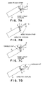
- FIGS. 7A through 7D are illustrations showing that the quantity of radiated vertical polarization varies when the first preferred embodiment of a portable radio terminal according to according to the present invention is inclined to change the state of coupling;
- FIG. 8 is a circuit diagram showing the construction of the second preferred embodiment of load changing means according to the present invention.
- FIG. 9 is a schematic diagram showing the construction of the third preferred embodiment of load changing means according to the present invention.
- FIG. 10 is a schematic diagram showing the construction of the fourth preferred embodiment of load changing means according to the present invention.
- FIG. 11 is a perspective view showing the construction of the sixth preferred embodiment of a portable radio terminal according to the present invention.
- FIGS. 13A through 13F are illustrations schematically showing the construction or shape of a liner matching element serving as load changing means.
- FIG. 4 shows the construction of the first preferred embodiment of a portable radio terminal according to the present invention.
- the portable radio terminal 1 comprises: a housing 2 ; a linear antenna 3 ; a radio circuit included in the housing 2 ; a matching circuit 6 mounted on the top of the housing 2 at a position offset from a longitudinal center line 5 of the housing 2 ; and a load 7 connected to the tip of the matching circuit 6 .
- the load 7 is connected to the linear antenna 3 , and includes load changing means 10 (the details of which are not shown in FIG. 4) configured to change the value of the load 7 , and a control circuit 8 for controlling the load changing means 10 .
- the lower end of the matching circuit 6 is provided with a feeder line 9 , through which the output of the radio circuit 4 is fed to the matching circuit 6 .
- the load changing means By the load changing means, the coupling state between the matching circuit 6 and the linear antenna 3 can be changed.
- the load changing means 10 includes the load 7 in FIG. 4, the load changing means 10 has the function of changing the value of the load 7 between the linear antenna 3 and the matching circuit 6 with any one of constructions which will be described later.
- the linear antenna 3 is a monopole antenna having a length of a half-wavelength and that the matching circuit 6 is an element electrically having a length of a quarter wavelength.
- the combination of the matching circuit 6 with the linear antenna element 3 has a length of a three quarter wavelength, and equivalently operates as a monopole antenna, so that the impedance of the antenna viewed from the feeding point approximates 50 ⁇ .
- the impedance of the feeder line 9 is easily matched with the impedance of the antenna 3 .
- the matching circuit 6 may comprise a distributed element or a lumped element.
- the distributed element may comprise a strip line having a length of a quarter wavelength
- the lumped element may comprise an LC series resonance circuit wherein an L (inductance) is arranged in the vicinity of the feeding point.
- the matching circuit 6 may comprise a linear matching element electrically having a length of a quarter wavelength.
- the load 7 is required to form the coupling state between the matching circuit 6 and the linear antenna 3 as the short-circuit coupling (0 ⁇ ), the capacitive coupling or the loose coupling ( ⁇ ⁇ ).
- the matching circuit 6 may be connected to the linear antenna 3 in the form of direct current.
- the load 7 may be a short-circuiting line.
- the linear antenna 3 and the matching circuit 6 may be arranged so as to be apart from each other via a space at an interval (e.g., about a fraction of a wavelength). In this case, the load 7 is the space, and the value of the load is ⁇ ⁇ .
- the capacitive coupling there are two methods, one of which is a method for arranging the matching circuit 6 so as to approach the linear antenna 3 via a space (e.g., about a friction of tenth wavelength), and the other of which is a method using a capacitor as the load 7 .
- a space e.g., about a friction of tenth wavelength
- the other of which is a method using a capacitor as the load 7 .
- the portable radio terminal is held in a user's hand to be inclined at an angle of 60° with respect to the ground to be used near the user's head.
- the linear antenna 3 is inclined at an angle of 60° as shown in FIG. 5, horizontally polarized waves are mainly emitted. Because, if the antenna is decomposed into a horizontal component and a vertical component, the horizontal component is the square root of three times as large as the vertical component, as can be clearly seen from a formula of 1:2: the square root of three.
- polarized waves emitted from the antenna of a base station are often vertically polarized waves as described above
- polarized waves emitted from the antenna of the portable radio terminal are also preferably vertically polarized waves in order to enhance polarization efficiency.
- radio waves emitted from the portable radio terminal are not only emitted from the antenna, but the waves are also emitted from the housing.
- the radio waves emitted from the housing are mainly emitted from the edge portion of the housing. Because the high-frequency current flowing over the housing strongly exists on the edge of the housing to serve as a wave source of radiation.
- the top side 2 A of the housing 2 shown in FIG. 5 is only inclined at an angle of 30 degrees with respect to the vertical line to serve as a portion for emitting a large quantity of vertically polarized waves to serve as an important radiation source having an influence on radio communication.
- the high-frequency current also exists on the right and left edges of the housing 2 , this is ignored herein.
- the reasons for this are two reasons that the right and left edges of the housing are inclined at 60 degrees with respect to the vertical line to emit only a small quantity of vertically polarized waves and that most of the right and left edges of the housing are covered with the user's hand to decrease the quantity of radiation. That is, the radiation of vertically polarized waves from the ignored portion is not important for radio communication.
- the radiation from the linear antenna 3 is added to the radiation from the top side 2 A of the housing 2 , so that it is possible to carry out a good communication.
- the directions of currents serving as the wave sources of radiation must be the same. Therefore, in the portable radio terminal according to the present invention, the coincidence of the direction of the vector with the current on the housing is realized by changing the phase of the current on the antenna.
- a method for changing the current on the antenna is carried out by the value of the load 7 for connecting the linear antenna 3 to the matching circuit 6 .
- the operation for causing the current on the housing to be coincident with the vector by utilizing the variation in the current on the antenna which is changed by the variation in value of the load 7 will be described below.
- FIGS. 6A, 6 B and 6 C show the top side of the housing 2 and the current distribution on the linear antenna 3 , according to the present invention. The respective distributions are simply shown for explanation.
- FIG. 6A shows the case of the short-circuit coupling
- FIG. 6B shows the case of the capacitive coupling
- FIG. 6B shows the case of the loose coupling.
- the current on the top side 2 A of the housing 2 has the same phase as that at the feeding point on the basis of the phase of the current at the feeding point.
- the phase of the current on the linear antenna 3 is opposite to that at the feeding point. Because the current is supplied to the antenna 3 so as to include a phase delay by the matching circuit 6 having the length of a quarter wavelength.
- both of the directions of the current on the top side 2 A of the housing 2 and the current on the linear antenna 2 are directions in which the currents leave the feeding point as shown in the figure.
- the phase of the current on the linear antenna 3 approaches the phase of the current at the feeding point.
- the reason why the capacitive coupling is different from the short-circuit coupling shown in FIG. 6A is that the phase lag of the current proceeds by the capacity of the load 7 .
- the current on the top side 2 A of the housing 2 flows in a direction in which the current leaves the feeding point similar to the case of FIG. 6A
- the current on the linear antenna 3 flows toward the feeding point unlike the case of FIG. 6 A.
- the loose coupling shown in FIG. 6C no current exists on the linear antenna 3 , so that no arrow is shown.
- FIG. 7A shows a case where the terminal is held so that the antenna is arranged on the lower side and where the load 7 forms the short-circuit coupling.
- the current distributions of the linear antenna 3 and the top side 2 A of the housing 2 are divided into vertical and horizontal components.
- both of the vertical component of the linear antenna 3 and the vertical component of the top side 2 A of the housing 2 are directed upwards, so that these vertical components are added to each other.
- the vertical polarization component of radio waves emitted from the antenna increases. That is, according to the present invention, it is possible to realize an antenna of a portable radio terminal capable of finely emitting vertically polarized waves even if the terminal is held so that the antenna is arranged on the lower side.
- FIG. 7B shows a case where the terminal is held so that the antenna is arranged on the upper side and where the load 7 forms the capacitive coupling.
- the current distributions of the linear antenna 3 and the top side 2 A of the housing 2 are divided into vertical and horizontal components.
- both of the vertical component of the linear antenna 3 and the vertical component of the top side 2 A of the housing 2 are directed downwards, so that these vertical components are added to each other.
- the vertical polarization component of radio waves emitted from the antenna increases. That is, according to the present invention, it is possible to realize an antenna of a portable radio terminal capable of finely emitting vertically polarized waves even if the terminal is held so that the antenna is arranged on the upper side.
- the matching circuit 6 is a small helical antenna to be also operated as an antenna.
- This antenna has a smaller quantity of radiation than that of the linear antenna 3 having a half-wavelength, so that this quantity of radiation can be ignored in the case of the short-circuit coupling and in the case of the capacitive coupling.
- the antenna contacts a large ear ring or a metal article mounted on a hat, a cap or the like to vary its characteristics to deteriorate its performance.
- only the helical antenna is preferably used without the need of the linear antenna 3 .
- the linear antenna 3 may be connected to the helical antenna by the loose coupling to operate only the helical antenna.
- the load changing means 10 can electrically change the coupling state by the plurality of reactances (L) 14 a , 14 b and 14 c and the high-frequency switches 13 a and 13 b connected thereto.
- the high-frequency switch may comprise a PIN diode or a metal semiconductor field effect transistor (MESFET).
- each of the reactances (L) 14 a , 14 b and 14 c may comprise a choke coil for interrupting high frequency waves, and the bias voltage sources 15 a and 15 are designed to operate the MESFETs 13 a and 13 b , respectively.
- the first switch 16 a is turned ON, a bias voltage is applied to the first MESFET 13 a which is in a short-circuit state as a high frequency. Then, if the second switch 16 b is turned OFF, the second MESFET 13 b is in an open state as a high frequency since no bias voltage is applied to the second MESFET 13 b . As a result, the first port 11 is connected to the second port 12 via the first MESFET 13 a which is in the short-circuit state, so that it is possible to realize the short-circuit coupling between the matching circuit 6 and the linear antenna 3 .
- the load changing means 10 capable of electrically changing the coupling state, so that it is possible to realize good radio communication. Furthermore, this imposes no burden on a person who uses the terminal since the coupling state can be electrically switched.
- the third preferred embodiment it is not required to provide any electrically complicated constructions unlike the second preferred embodiment, so that the construction is simple. Although this operation is carried out by the user, it is not complicated and troublesome with respect to the extension and housing of the linear antenna 3 . According to the present invention, it is possible to sufficiently obtain advantages if the on-off control action of the mechanical switches 18 a and 18 b is not frequently carried out.
- a user's hand in which a portable radio terminal is held tends to be one-sided, and tends to be the opposite hand to the user's dominant hand, although there are differences among individuals.
- the mechanical switches 18 a and 18 b may be previously turned on so as to improve the characteristics of the antenna in that state, and the mechanical switches 18 a and 18 b may be switched only when the portable radio terminal is held in another hand.
- the principle of operation for switching the coupling is the same as that when the coupling is electrically switched, so that the description thereof is omitted.
- FIG. 10 shows the construction of the fourth preferred embodiment of load changing means according to the present invention.
- the load changing means also has the function of adjusting the whole length of a combined antenna comprising the matching circuit 6 and the linear antenna 3 .
- a length adjusting element 19 is provided for increasing the length of a pass in the case of the short-circuit coupling. If the length adjusting element 19 is set to be equal to the electric length of the capacitor 17 for forming the capacitive coupling, the resonance frequency can be constant even if the coupling is changed, so that it is possible to carry out a good communication.
- the length adjusting element 19 may be a linear element having a helical shape, a linear element having a meander shape, a micro strip line formed on a substrate, or any one of elements which can obtain the same effect.
- This fifth preferred embodiment relates to the electrical switching of the coupling state.
- load changing means is controlled so that the receiving state of the radio circuit 4 is optimum.
- the control circuit 9 monitors the receiving state of the radio circuit 4 to control the coupling state so as to maximize the receiving sensitivity.
- TDMA time division multiple access
- FIG. 11 shows the construction of the sixth preferred embodiment of a portable radio terminal according to the present invention.
- the same reference numbers are given to the same or corresponding elements as or to those in FIG. 4 or other figures, so that the duplicated descriptions thereof are omitted.
- the linear antenna 3 is designed to be retractable in the housing 2 .
- the lower end of the linear antenna 3 is connected to the load 7 when the linear antenna 3 is extended from the housing 2
- the upper end of the linear antenna 3 is connected to the load 7 when the linear antenna 3 is retracted into the housing 2 .
- the matching circuit 6 may be a linear matching element such as a small helical antenna.
- the linear antenna 3 When the linear antenna 3 is extended from the housing 2 to be used, the description thereof is the same as the above description to be omitted herein.
- the linear antenna 3 When the linear antenna 3 is retracted into the housing 2 , the operation is switched by the load changing means for changing the load 7 .
- the coupling state is changed to the loose coupling, only the linear matching element serving as the matching circuit 6 is operated, so that the linear antenna 3 does not equivalently exist.
- the coupling state is changed to the short-circuit coupling or the capacitive coupling, both of the small antenna and the linear antenna 3 are operated.
- the advantages of the changing of the coupling state are as follows. It is considered that the retracted state is a waiting state. It is therefore considered that the portable radio terminal is in various states that it is housed in a bag or a pocket of pants. That is, in such states, it is desired that the portable radio terminal has a plurality of antenna forms to select the optimum antenna form therefrom. Thus, even if the linear antenna 3 is retracted into the housing 2 , it is possible to carry out good radio communication regardless of the surrounding environment by changing the means for changing the load 7 .
- FIG. 12 shows the construction of the seventh preferred embodiment of a portable radio terminal according to the present invention.
- the feature of this seventh preferred embodiment is that the matching circuit 6 , the load 7 and the load changing means (not shown in FIG. 12) are included in the housing 2 .
- the load changing means (not shown) may be formed on the substrate in the housing 2 , so that there are advantages in that the terminal can be easily produced to decrease the costs. Moreover, since only the linear antenna 3 apparently exists outside of the housing 2 , the portable radio terminal has strongly resistant to shock when it drops or the like.
- a meander element 20 having an electric length of a quarter wavelength may be similarly formed as shown in FIG. 13 A. While the length of the matching circuit 6 has been a quarter-wavelength, the above-described effects can be expected if the length of the matching circuit 6 is a half-wavelength, a three quarter-wavelength or any length. In addition, even if the portable radio terminal is held in the user's left or right hand, the optimum antenna construction can be obtained.
- the linear antenna 3 has been the straight antenna having the half-wavelength, the above-described effect can be expected if the length of the antenna is a three quarter-wavelength, a wavelength or any length.
- the shape of the linear antenna 3 should not be limited to the straight shape, but the above described effects can be expected if the linear antenna 3 is wounded as a helical shape or bent as a meander shape, or has any shape.
- FIGS. 13A through 13F show some examples of matching circuits 6 of linear matching elements having predetermined shapes.
- the linear matching element serving as the matching circuit 6 is a meander matching element 20 which is formed so as to have a meander shape as the predetermined shape.
- the linear matching element serving as the matching circuit 6 is a zigzag-shaped matching element 21 which is formed so as to have a zigzag shape as the predetermined shape.
- the linear matching element serving as the matching circuit 6 is a helical matching element 22 which is formed so as to have a helical shape as the predetermined shape.
- the linear matching element serving as the matching circuit is a conical matching element 23 which is formed so as to have a conical helical shape as the predetermined shape.
- the linear matching element serving as the matching circuit is a rectangular helical matching element 24 which is formed so as to have a rectangular helical shape as the predetermined shape.
- the linear matching element serving as the matching circuit 6 is a pyramid helical shape as the predetermined shape.
- the capacitive coupling has been formed by the method for connecting the matching circuit 6 to the linear antenna 3 via a space and the method for inserting the capacitor, the physical dimension of the space and the value of the capacitor may be previously optimally determined by a simulation or experiment.
- the portable radio terminal according to the present invention has portions, the constructions of which are slightly similar to those of conventional portable radio terminals, the portable radio terminal according to the present invention is provided with the load changing means for changing the load, which has not been provided in the conventional portable radio terminal. Therefore, even if the portable radio terminal is held in any one of the user's left and light hands, the quantity of radiation of vertically polarized waves increases, so that it is possible to realize good radio communication with relatively simple constructions.
- the quantity of radiation of vertically polarized waves has been increased in the above-described preferred embodiments
- the quantity of radiation of horizontally polarized waves may be increased by the combination of the constructions shown in FIGS. 7C and 7D. Therefore, even if the base station will emit horizontally polarized waves in future, the horizontally polarized waves can be finely received according to the present invention.
- the quantity of radiation of the vertically polarized waves can be increased by switching the coupling state between the matching circuit and the linear antenna even if the terminal is held in the user's left or right hand, so that it is possible to realize good radio communication.
Landscapes
- Engineering & Computer Science (AREA)
- Computer Networks & Wireless Communication (AREA)
- Signal Processing (AREA)
- Support Of Aerials (AREA)
- Telephone Set Structure (AREA)
- Transceivers (AREA)
- Details Of Aerials (AREA)
Priority Applications (1)
| Application Number | Priority Date | Filing Date | Title |
|---|---|---|---|
| US10/761,328 US7079878B2 (en) | 2000-02-09 | 2004-01-22 | Portable radio terminal capable of obtaining good polarization efficiency regardless of position and direction of antenna |
Applications Claiming Priority (3)
| Application Number | Priority Date | Filing Date | Title |
|---|---|---|---|
| JP2000032087A JP3629176B2 (ja) | 2000-02-09 | 2000-02-09 | 携帯無線端末 |
| JP2000-32087 | 2000-02-09 | ||
| JP2000-032087 | 2000-02-09 |
Related Child Applications (1)
| Application Number | Title | Priority Date | Filing Date |
|---|---|---|---|
| US10/761,328 Continuation US7079878B2 (en) | 2000-02-09 | 2004-01-22 | Portable radio terminal capable of obtaining good polarization efficiency regardless of position and direction of antenna |
Publications (2)
| Publication Number | Publication Date |
|---|---|
| US20010012768A1 US20010012768A1 (en) | 2001-08-09 |
| US6701167B2 true US6701167B2 (en) | 2004-03-02 |
Family
ID=18556743
Family Applications (2)
| Application Number | Title | Priority Date | Filing Date |
|---|---|---|---|
| US09/777,911 Expired - Fee Related US6701167B2 (en) | 2000-02-09 | 2001-02-07 | Portable radio terminal capable of obtaining good polarization efficiency regardless of position and direction of antenna |
| US10/761,328 Expired - Fee Related US7079878B2 (en) | 2000-02-09 | 2004-01-22 | Portable radio terminal capable of obtaining good polarization efficiency regardless of position and direction of antenna |
Family Applications After (1)
| Application Number | Title | Priority Date | Filing Date |
|---|---|---|---|
| US10/761,328 Expired - Fee Related US7079878B2 (en) | 2000-02-09 | 2004-01-22 | Portable radio terminal capable of obtaining good polarization efficiency regardless of position and direction of antenna |
Country Status (5)
| Country | Link |
|---|---|
| US (2) | US6701167B2 (fr) |
| EP (1) | EP1124280A3 (fr) |
| JP (1) | JP3629176B2 (fr) |
| KR (1) | KR100398757B1 (fr) |
| CN (1) | CN1201613C (fr) |
Cited By (4)
| Publication number | Priority date | Publication date | Assignee | Title |
|---|---|---|---|---|
| US20040041734A1 (en) * | 2002-08-30 | 2004-03-04 | Fujitsu Limited | Antenna apparatus including inverted-F antenna having variable resonance frequency |
| US20050143151A1 (en) * | 2003-12-24 | 2005-06-30 | Takayoshi Ito | Foldable mobile terminal |
| US20050225496A1 (en) * | 2002-12-20 | 2005-10-13 | Apostolos John T | Meander line antenna coupler and shielded meander line |
| US7209092B2 (en) * | 2003-03-03 | 2007-04-24 | Bae Systems Information And Electronic Systems Integration Inc. | Symmetric, shielded slow wave meander line |
Families Citing this family (8)
| Publication number | Priority date | Publication date | Assignee | Title |
|---|---|---|---|---|
| US20080102760A1 (en) * | 2006-10-02 | 2008-05-01 | Sierra Wireless, Inc. | Centralized wireless communication system |
| US8116831B2 (en) | 2007-11-29 | 2012-02-14 | Motorola Mobility, Inc. | Hand-held communication device with auxiliary input apparatus, and method |
| CN201138685Y (zh) * | 2007-12-28 | 2008-10-22 | 深圳华为通信技术有限公司 | 一种无线终端天线 |
| KR101591525B1 (ko) * | 2009-09-11 | 2016-02-04 | 삼성전자주식회사 | 휴대단말기의 안테나 성능 보완 장치 |
| EP2515415A4 (fr) * | 2009-12-16 | 2016-11-09 | Fujitsu Ltd | Appareil d'émission d'énergie par couplage magnétique résonant et appareil de réception d'énergie par couplage magnétique résonant |
| CN102638609B (zh) | 2011-02-10 | 2015-11-11 | 三星电子株式会社 | 移动终端和考虑通信环境来控制移动终端的方法 |
| USD841610S1 (en) * | 2017-04-22 | 2019-02-26 | Innovative Dimmers, LLC | Wireless transceiver for controlling professional visual effects devices |
| US10965019B1 (en) | 2017-04-23 | 2021-03-30 | Innovative Dimmers, LLC | Wireless transceiver for controlling professional lights and special effects devices |
Citations (9)
| Publication number | Priority date | Publication date | Assignee | Title |
|---|---|---|---|---|
| US3622890A (en) | 1968-01-31 | 1971-11-23 | Matsushita Electric Industrial Co Ltd | Folded integrated antenna and amplifier |
| EP0611199A1 (fr) | 1993-02-11 | 1994-08-17 | Alcatel Mobile Communication France | Radio émetteur-récepteur portable comportant une antenne ayant un diagramme de rayonnement practiquement vertical |
| EP0652646A1 (fr) | 1993-11-05 | 1995-05-10 | AT&T Corp. | Appareil pour maintenir verticalement la position d'une antenne employée dans un émetteur-récepteur portable |
| US5634203A (en) * | 1994-09-02 | 1997-05-27 | Motorola Inc. | Adaptive multi-receiver shared antenna matching system and method |
| US5969688A (en) | 1994-04-26 | 1999-10-19 | Ireland; Frank E. | Cellular phone antenna with reactance cancellation |
| WO1999065108A1 (fr) | 1998-06-10 | 1999-12-16 | Matsushita Electric Industrial Co., Ltd. | Antenne radio |
| US6064868A (en) * | 1995-08-24 | 2000-05-16 | Kobayashi; Yasuhiro | Antenna tuning controller |
| US6104356A (en) | 1995-08-25 | 2000-08-15 | Uniden Corporation | Diversity antenna circuit |
| US6526263B1 (en) * | 1998-08-28 | 2003-02-25 | Nec Corporation | Antenna impedance adjuster |
Family Cites Families (2)
| Publication number | Priority date | Publication date | Assignee | Title |
|---|---|---|---|---|
| US5969683A (en) * | 1997-05-20 | 1999-10-19 | Ericsson Inc. | Radiotelephones with antenna matching switching system configurations |
| US6104358A (en) * | 1998-05-12 | 2000-08-15 | Trw Inc. | Low cost deployable reflector |
-
2000
- 2000-02-09 JP JP2000032087A patent/JP3629176B2/ja not_active Expired - Fee Related
-
2001
- 2001-02-06 EP EP01301014A patent/EP1124280A3/fr not_active Withdrawn
- 2001-02-07 US US09/777,911 patent/US6701167B2/en not_active Expired - Fee Related
- 2001-02-07 KR KR10-2001-0005894A patent/KR100398757B1/ko not_active Expired - Fee Related
- 2001-02-08 CN CNB011032596A patent/CN1201613C/zh not_active Expired - Fee Related
-
2004
- 2004-01-22 US US10/761,328 patent/US7079878B2/en not_active Expired - Fee Related
Patent Citations (9)
| Publication number | Priority date | Publication date | Assignee | Title |
|---|---|---|---|---|
| US3622890A (en) | 1968-01-31 | 1971-11-23 | Matsushita Electric Industrial Co Ltd | Folded integrated antenna and amplifier |
| EP0611199A1 (fr) | 1993-02-11 | 1994-08-17 | Alcatel Mobile Communication France | Radio émetteur-récepteur portable comportant une antenne ayant un diagramme de rayonnement practiquement vertical |
| EP0652646A1 (fr) | 1993-11-05 | 1995-05-10 | AT&T Corp. | Appareil pour maintenir verticalement la position d'une antenne employée dans un émetteur-récepteur portable |
| US5969688A (en) | 1994-04-26 | 1999-10-19 | Ireland; Frank E. | Cellular phone antenna with reactance cancellation |
| US5634203A (en) * | 1994-09-02 | 1997-05-27 | Motorola Inc. | Adaptive multi-receiver shared antenna matching system and method |
| US6064868A (en) * | 1995-08-24 | 2000-05-16 | Kobayashi; Yasuhiro | Antenna tuning controller |
| US6104356A (en) | 1995-08-25 | 2000-08-15 | Uniden Corporation | Diversity antenna circuit |
| WO1999065108A1 (fr) | 1998-06-10 | 1999-12-16 | Matsushita Electric Industrial Co., Ltd. | Antenne radio |
| US6526263B1 (en) * | 1998-08-28 | 2003-02-25 | Nec Corporation | Antenna impedance adjuster |
Non-Patent Citations (1)
| Title |
|---|
| K. Meksamoot, et al., International Symposium on Antennas and Propagation, 4 pages, "Effect of Human Interaction on Diversity Performance of Polarization Diversity PIFA on Portable Telephone", 2000. |
Cited By (7)
| Publication number | Priority date | Publication date | Assignee | Title |
|---|---|---|---|---|
| US20040041734A1 (en) * | 2002-08-30 | 2004-03-04 | Fujitsu Limited | Antenna apparatus including inverted-F antenna having variable resonance frequency |
| US7372406B2 (en) | 2002-08-30 | 2008-05-13 | Fujitsu Limited | Antenna apparatus including inverted-F antenna having variable resonance frequency |
| US20050225496A1 (en) * | 2002-12-20 | 2005-10-13 | Apostolos John T | Meander line antenna coupler and shielded meander line |
| US7190322B2 (en) * | 2002-12-20 | 2007-03-13 | Bae Systems Information And Electronic Systems Integration Inc. | Meander line antenna coupler and shielded meander line |
| US7209092B2 (en) * | 2003-03-03 | 2007-04-24 | Bae Systems Information And Electronic Systems Integration Inc. | Symmetric, shielded slow wave meander line |
| US20050143151A1 (en) * | 2003-12-24 | 2005-06-30 | Takayoshi Ito | Foldable mobile terminal |
| US7444175B2 (en) | 2003-12-24 | 2008-10-28 | Kabushiki Kaisha Toshiba | Foldable mobile terminal with antennas and a selector selecting a diversity transceiving system based on folding-out or folding-in terminal |
Also Published As
| Publication number | Publication date |
|---|---|
| CN1308477A (zh) | 2001-08-15 |
| US20010012768A1 (en) | 2001-08-09 |
| EP1124280A2 (fr) | 2001-08-16 |
| JP2001223507A (ja) | 2001-08-17 |
| KR20010078780A (ko) | 2001-08-21 |
| KR100398757B1 (ko) | 2003-09-19 |
| US7079878B2 (en) | 2006-07-18 |
| JP3629176B2 (ja) | 2005-03-16 |
| US20040152497A1 (en) | 2004-08-05 |
| CN1201613C (zh) | 2005-05-11 |
| EP1124280A3 (fr) | 2002-10-30 |
Similar Documents
| Publication | Publication Date | Title |
|---|---|---|
| US6549169B1 (en) | Antenna for mobile wireless communications and portable-type wireless apparatus using the same | |
| JP3864127B2 (ja) | デュアルフィーディングポートを有するマルチバンドチップアンテナ及びこれを用いる移動通信装置 | |
| US6701167B2 (en) | Portable radio terminal capable of obtaining good polarization efficiency regardless of position and direction of antenna | |
| US6781545B2 (en) | Broadband chip antenna | |
| JPH10284919A (ja) | アンテナ装置 | |
| KR20000062747A (ko) | 안테나 장치 | |
| JPH02174404A (ja) | 移動通信用平板アンテナ | |
| JP2006512003A (ja) | 携帯型無線機器用小体積アンテナ | |
| JP2001136026A (ja) | 携帯無線端末 | |
| US6172646B1 (en) | Antenna apparatus and communication apparatus using the antenna apparatus | |
| JPH11163756A (ja) | 携帯無線機 | |
| CN105789845A (zh) | 智能手表及其全频段调谐天线 | |
| GB2357376A (en) | Antenna Unit | |
| JP2001189615A (ja) | 移動無線用アンテナおよび、それを用いた携帯型無線機 | |
| JP3586929B2 (ja) | 携帯無線機器用アンテナおよび携帯無線機器 | |
| JP2004274729A (ja) | 携帯無線通信装置 | |
| JP2004274730A (ja) | 携帯無線通信装置 | |
| JPH08307130A (ja) | 携帯無線機器用アンテナおよび携帯無線機器 | |
| US6201503B1 (en) | Antenna for radio device and radio device | |
| JPH0936628A (ja) | 携帯無線機器用アンテナ | |
| JP3460887B2 (ja) | 無線機 | |
| JP2004040154A (ja) | 携帯無線機用アンテナ及び携帯無線機 | |
| KR100533625B1 (ko) | 간접 급전 방식을 이용한 트리플 밴드 내장형 안테나 | |
| JPH0779205B2 (ja) | アンテナ装置 | |
| KR20100026333A (ko) | 주파수 대역의 가변이 가능한 역 에프 안테나 |
Legal Events
| Date | Code | Title | Description |
|---|---|---|---|
| AS | Assignment |
Owner name: KABUSHIKI KAISHA TOSHIBA, JAPAN Free format text: ASSIGNMENT OF ASSIGNORS INTEREST;ASSIGNORS:ODACHI, NORIAKI;SEKINE, SYUICHI;REEL/FRAME:011550/0332 Effective date: 20010126 |
|
| FPAY | Fee payment |
Year of fee payment: 4 |
|
| FPAY | Fee payment |
Year of fee payment: 8 |
|
| REMI | Maintenance fee reminder mailed | ||
| LAPS | Lapse for failure to pay maintenance fees | ||
| STCH | Information on status: patent discontinuation |
Free format text: PATENT EXPIRED DUE TO NONPAYMENT OF MAINTENANCE FEES UNDER 37 CFR 1.362 |
|
| STCH | Information on status: patent discontinuation |
Free format text: PATENT EXPIRED DUE TO NONPAYMENT OF MAINTENANCE FEES UNDER 37 CFR 1.362 |
|
| FP | Lapsed due to failure to pay maintenance fee |
Effective date: 20160302 |