US6709727B1 - Bookbinding structure and method - Google Patents
Bookbinding structure and method Download PDFInfo
- Publication number
- US6709727B1 US6709727B1 US09/684,582 US68458200A US6709727B1 US 6709727 B1 US6709727 B1 US 6709727B1 US 68458200 A US68458200 A US 68458200A US 6709727 B1 US6709727 B1 US 6709727B1
- Authority
- US
- United States
- Prior art keywords
- substrate
- stack
- release liner
- adhesive matrix
- edge
- Prior art date
- Legal status (The legal status is an assumption and is not a legal conclusion. Google has not performed a legal analysis and makes no representation as to the accuracy of the status listed.)
- Expired - Lifetime, expires
Links
Images





Classifications
-
- B—PERFORMING OPERATIONS; TRANSPORTING
- B42—BOOKBINDING; ALBUMS; FILES; SPECIAL PRINTED MATTER
- B42D—BOOKS; BOOK COVERS; LOOSE LEAVES; PRINTED MATTER CHARACTERISED BY IDENTIFICATION OR SECURITY FEATURES; PRINTED MATTER OF SPECIAL FORMAT OR STYLE NOT OTHERWISE PROVIDED FOR; DEVICES FOR USE THEREWITH AND NOT OTHERWISE PROVIDED FOR; MOVABLE-STRIP WRITING OR READING APPARATUS
- B42D3/00—Book covers
- B42D3/002—Covers or strips provided with adhesive for binding
-
- B—PERFORMING OPERATIONS; TRANSPORTING
- B42—BOOKBINDING; ALBUMS; FILES; SPECIAL PRINTED MATTER
- B42C—BOOKBINDING
- B42C9/00—Applying glue or adhesive peculiar to bookbinding
- B42C9/0056—Applying glue or adhesive peculiar to bookbinding applying tape or covers precoated with adhesive to a stack of sheets
-
- Y—GENERAL TAGGING OF NEW TECHNOLOGICAL DEVELOPMENTS; GENERAL TAGGING OF CROSS-SECTIONAL TECHNOLOGIES SPANNING OVER SEVERAL SECTIONS OF THE IPC; TECHNICAL SUBJECTS COVERED BY FORMER USPC CROSS-REFERENCE ART COLLECTIONS [XRACs] AND DIGESTS
- Y10—TECHNICAL SUBJECTS COVERED BY FORMER USPC
- Y10S—TECHNICAL SUBJECTS COVERED BY FORMER USPC CROSS-REFERENCE ART COLLECTIONS [XRACs] AND DIGESTS
- Y10S412/00—Bookbinding: process and apparatus
- Y10S412/90—Activating previously applied adhesive
-
- Y—GENERAL TAGGING OF NEW TECHNOLOGICAL DEVELOPMENTS; GENERAL TAGGING OF CROSS-SECTIONAL TECHNOLOGIES SPANNING OVER SEVERAL SECTIONS OF THE IPC; TECHNICAL SUBJECTS COVERED BY FORMER USPC CROSS-REFERENCE ART COLLECTIONS [XRACs] AND DIGESTS
- Y10—TECHNICAL SUBJECTS COVERED BY FORMER USPC
- Y10S—TECHNICAL SUBJECTS COVERED BY FORMER USPC CROSS-REFERENCE ART COLLECTIONS [XRACs] AND DIGESTS
- Y10S412/00—Bookbinding: process and apparatus
- Y10S412/901—Pressure sensitive adhesive
-
- Y—GENERAL TAGGING OF NEW TECHNOLOGICAL DEVELOPMENTS; GENERAL TAGGING OF CROSS-SECTIONAL TECHNOLOGIES SPANNING OVER SEVERAL SECTIONS OF THE IPC; TECHNICAL SUBJECTS COVERED BY FORMER USPC CROSS-REFERENCE ART COLLECTIONS [XRACs] AND DIGESTS
- Y10—TECHNICAL SUBJECTS COVERED BY FORMER USPC
- Y10S—TECHNICAL SUBJECTS COVERED BY FORMER USPC CROSS-REFERENCE ART COLLECTIONS [XRACs] AND DIGESTS
- Y10S412/00—Bookbinding: process and apparatus
- Y10S412/902—Heating and pressing
-
- Y—GENERAL TAGGING OF NEW TECHNOLOGICAL DEVELOPMENTS; GENERAL TAGGING OF CROSS-SECTIONAL TECHNOLOGIES SPANNING OVER SEVERAL SECTIONS OF THE IPC; TECHNICAL SUBJECTS COVERED BY FORMER USPC CROSS-REFERENCE ART COLLECTIONS [XRACs] AND DIGESTS
- Y10—TECHNICAL SUBJECTS COVERED BY FORMER USPC
- Y10T—TECHNICAL SUBJECTS COVERED BY FORMER US CLASSIFICATION
- Y10T428/00—Stock material or miscellaneous articles
- Y10T428/14—Layer or component removable to expose adhesive
-
- Y—GENERAL TAGGING OF NEW TECHNOLOGICAL DEVELOPMENTS; GENERAL TAGGING OF CROSS-SECTIONAL TECHNOLOGIES SPANNING OVER SEVERAL SECTIONS OF THE IPC; TECHNICAL SUBJECTS COVERED BY FORMER USPC CROSS-REFERENCE ART COLLECTIONS [XRACs] AND DIGESTS
- Y10—TECHNICAL SUBJECTS COVERED BY FORMER USPC
- Y10T—TECHNICAL SUBJECTS COVERED BY FORMER US CLASSIFICATION
- Y10T428/00—Stock material or miscellaneous articles
- Y10T428/14—Layer or component removable to expose adhesive
- Y10T428/1476—Release layer
-
- Y—GENERAL TAGGING OF NEW TECHNOLOGICAL DEVELOPMENTS; GENERAL TAGGING OF CROSS-SECTIONAL TECHNOLOGIES SPANNING OVER SEVERAL SECTIONS OF THE IPC; TECHNICAL SUBJECTS COVERED BY FORMER USPC CROSS-REFERENCE ART COLLECTIONS [XRACs] AND DIGESTS
- Y10—TECHNICAL SUBJECTS COVERED BY FORMER USPC
- Y10T—TECHNICAL SUBJECTS COVERED BY FORMER US CLASSIFICATION
- Y10T428/00—Stock material or miscellaneous articles
- Y10T428/14—Layer or component removable to expose adhesive
- Y10T428/1481—Dissimilar adhesives
-
- Y—GENERAL TAGGING OF NEW TECHNOLOGICAL DEVELOPMENTS; GENERAL TAGGING OF CROSS-SECTIONAL TECHNOLOGIES SPANNING OVER SEVERAL SECTIONS OF THE IPC; TECHNICAL SUBJECTS COVERED BY FORMER USPC CROSS-REFERENCE ART COLLECTIONS [XRACs] AND DIGESTS
- Y10—TECHNICAL SUBJECTS COVERED BY FORMER USPC
- Y10T—TECHNICAL SUBJECTS COVERED BY FORMER US CLASSIFICATION
- Y10T428/00—Stock material or miscellaneous articles
- Y10T428/14—Layer or component removable to expose adhesive
- Y10T428/1486—Ornamental, decorative, pattern, or indicia
-
- Y—GENERAL TAGGING OF NEW TECHNOLOGICAL DEVELOPMENTS; GENERAL TAGGING OF CROSS-SECTIONAL TECHNOLOGIES SPANNING OVER SEVERAL SECTIONS OF THE IPC; TECHNICAL SUBJECTS COVERED BY FORMER USPC CROSS-REFERENCE ART COLLECTIONS [XRACs] AND DIGESTS
- Y10—TECHNICAL SUBJECTS COVERED BY FORMER USPC
- Y10T—TECHNICAL SUBJECTS COVERED BY FORMER US CLASSIFICATION
- Y10T428/00—Stock material or miscellaneous articles
- Y10T428/24—Structurally defined web or sheet [e.g., overall dimension, etc.]
- Y10T428/24777—Edge feature
-
- Y—GENERAL TAGGING OF NEW TECHNOLOGICAL DEVELOPMENTS; GENERAL TAGGING OF CROSS-SECTIONAL TECHNOLOGIES SPANNING OVER SEVERAL SECTIONS OF THE IPC; TECHNICAL SUBJECTS COVERED BY FORMER USPC CROSS-REFERENCE ART COLLECTIONS [XRACs] AND DIGESTS
- Y10—TECHNICAL SUBJECTS COVERED BY FORMER USPC
- Y10T—TECHNICAL SUBJECTS COVERED BY FORMER US CLASSIFICATION
- Y10T428/00—Stock material or miscellaneous articles
- Y10T428/24—Structurally defined web or sheet [e.g., overall dimension, etc.]
- Y10T428/24777—Edge feature
- Y10T428/24793—Comprising discontinuous or differential impregnation or bond
Definitions
- Binder strips are used to bind pages together to form a book in which the binder strip forms the spine of the book.
- Binder strips which use a heat activated adhesives of low and high viscosity are used to bind a stack of sheets using heat and pressure which are applied to the strip and stack using a special purpose binding machine.
- Such prior art binder strips are, however, not suitable for some applications due to the appearance of books bound by such strips.
- the spines of books bound by the conventional binder strips are often devoid of any printed information because the binder strips require specialized equipment for printing on the strip.
- a conventional binder strip cannot provide a bound book having a cover with such a continuous design.
- FIG. 1A shows one embodiment of a prior art binder strip which permits a cover to be added after the binding sequence is completed.
- FIG. 1A is an exploded perspective view of the various layers of a first embodiment of the prior art bookbinding structure 1 .
- the bookbinding structure 1 includes an elongated substrate 6 having a length which corresponds to the length of the stack of pages (not depicted) to be bound and a width which exceeds the thickness of the stack by at least a minimum amount so that the edges of the substrate 6 will extend around the edge of the stack and slightly over the front and back pages of the stack, as will be described.
- Substrate 6 is preferably made of a formable material such as heavy weight paper.
- a layer of pressure activated adhesive 3 is disposed on one surface of the substrate 6 , with a heat activated adhesive matrix 4 being disposed facing the opposite substrate surface.
- the pressure activated adhesive 3 is typically a permanently binding adhesive which, once activated by applying pressure, produces a relatively permanent bond.
- One such pressure activated adhesive is sold under the designation HL-2593 by H. B. Fuller Company of St. Paul, Minn.
- the Fuller HL-2593 pressure activated adhesive can be subjected briefly to high temperatures, up to about 425 degrees F, without decomposing.
- the ability of the pressure activated adhesive 3 to withstand high temperatures is important because the bookbinding structure 1 is subjected briefly to high temperatures during the binding process, which will be described in more detail below.
- the pressure activated adhesive is preferably 0.003 to 0.005 inches thick.
- the pressure activated adhesive 3 is covered with a removable release liner 5 , as shown in FIG. 1A, to act as a barrier between the pressure activated adhesive 3 and the environment.
- the release liner 5 is preferably a silicon coated paper, such as made by Akrosil, Inc. of Menasha, Wis. under the designation Silox ® SBL60SC F1U/F4B.
- the surfaces of the coated paper can have varying release levels, with a low or easy release level indicating that the paper can be separated with little force and a high or tight release level indicating the separation requires a relatively large amount of force.
- the designation F4B indicates that the release level of the liner surface contacting the pressure sensitive adhesive layer 3 has a medium release level, with the opposite surface of the liner having a low or easy release level as indicated by the designation F 1 U.
- the heat activated adhesive matrix 4 is comprised of a center adhesive 4 A which extends along the longitudinal axis of the substrate 6 and a pair of outer adhesive bands 4 B.
- the center adhesive band 4 A which is a heat activated adhesive of relatively low viscosity, is the primary adhesive for binding the pages together.
- the center adhesive 4 A is typically 0.015 inch thick.
- An adhesive, sold under the designation Cool Bind 34-1301 by National Starch & Chemical Company of Bridgewater, N.J., has been found to be suitable as the center adhesive band 4 A.
- the center adhesive band 4 A preferably extends over slightly less than the full length of the bookbinding structure 1 so that there are end gaps without the center adhesive 4 A.
- the center adhesive band is at least as wide as the thickness of the stack 13 to be bound so that all of the pages of the stack will be exposed to the low viscosity adhesive.
- the FIG. 1A bookbinding structure further includes an undercoat adhesive layer 7 disposed intermediate the adhesive matrix 4 and the substrate 6 .
- the undercoat adhesive is heat activated and is relatively thin, typically 0.003 inches thick.
- the undercoat is preferably the same type of adhesive used in the outer adhesive bands 14 B and functions to act as a barrier so as to prevent the low viscosity central adhesive band 4 A from passing through the substrate 6 .
- the undercoat adhesive prevents all of the low viscosity adhesive of central band 4 A from being drawn up between the pages of the stack which may leave essentially no adhesive intermediate the edges of the pages and the substrate 6 .
- the stack 13 is lowered on to the book cover 2 so that the bottom portion of the exposed adhesive contacts the cover.
- the adhesive 3 is very aggressive in order to secure the cover assembly 2 adequately.
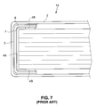
- FIG. 7 is a cross-sectional end view of the bound book using the first embodiment prior art bookbinding structure 1 which is not shown to scale so that all of the various layers can be seen.
- the cover assembly 2 is pre-scored at the two locations so that the cover assembly can easily be folded at the proper locations.
- the cover assembly 2 can be previously printed using any type of process, including printing processes that utilize heat sensitive inks since the cover assembly is never subjected to elevated temperatures when using the first embodiment bookbinding structure 1 .
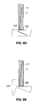
- FIG. 9A shows a cross-section of a bound book where the cover assembly covers that front and rear pages of the book together with the spine, as previously described in connection with FIG. 7 .
- FIG. 9B shows a bound book where the cover assembly 2 covers only the front page, a very small portion of the back page and the spine.
- FIG. 9C shows a bound book where the cover assembly 2 only covers the spine and a small portion of the front and back pages sufficient to cover the pressure sensitive adhesive.
- FIG. 2 depicts a conventional binding machine 8 such as described in U.S. Pat. No. 5,052,873.
- Machine 8 has a stack 13 to be bound inserted into the machine input. The thickness of the stack is automatically measured and the appropriate width binding structure I is displayed.
- the binding structure 1 is preferably available in three widths to accommodate stacks 13 of varying width. Such widths include “Narrow”, “Medium” and “Wide”, with the width of the central adhesive band 4 A being altered for each binder structure 1 width.
- Machine 8 will specify a structure 1 width having a central adhesive 4 A width that is at least as wide as the measured thickness of the stack 13 .
- a binding structure 1 of the appropriate width is then manually fed into the strip feed input of the machine 8 .
- the machine then automatically carries out the binding sequence by appropriately positioning the structure 1 relative to the edge of the stack 13 and applying a combination of heat and pressure as will be described.
- FIGS. 3A through 3F End views are shown of the stack 13 and the binding structure 1 .
- the stack 13 to be bound after loading, is gripped between a pair of clamps 10 and 11 and is initially supported on a cool platen 9 .
- a strip positioning apparatus (not depicted) positions the binding structure 1 previously fed into the machine so that the adhesive matrix 4 is facing the stack 13 .
- the vertical position of the structure 1 relative to the stack 13 is automatically set in accordance with the thickness of the stack as previously measured.
- a thin stack 13 will result in the structure 1 being positioned relatively high so that the edges of the structure 1 will extend equally over the front and rear pages of the bound stack.
- the rotating platen segment 12 A is rotated 90 degrees so that both the rotating and fixed platen segments 12 A and 12 B define a flat upper surface. This permits stack 13 to be moved to the right over the platen segments. This causes the bookbinding structure 1 to be folded around the lower edge of the stack 13 .
- the binding machine 8 pauses briefly in this position so that the central adhesive band 4 A will have time to become molten and to flow upward by way of capillary action between the individual pages of the stack 13 thereby fulling wetting the pages with the adhesive.
- the rotating platen segment 12 A is then rotated 90 degrees back to the original position as shown in FIG. 3 E.
- first embodiment bookbinding structure 1 could also be implemented without substrate 6 .
- undercoat adhesive layer 7 is disposed directly on the pressure activated adhesive layer 3 .
- the release liner 5 then provides the additional function of acting as a substrate and supporting the structure 1 during the binding sequence previously described in connection with FIGS. 3A through 3E.
- FIG. 1 B A second embodiment of the prior art bookbinding structure is depicted in FIG. 1 B.
- the second embodiment bookbinding structure 1 includes an adhesive matrix 4 similar to that of the first embodiment structure of FIG. 1A.
- a substrate 6 is provided having the same shape as that of the first embodiment, with there being an undercoat adhesive layer 7 similar to layer 7 of FIG. 1 A.
- the second embodiment structure 1 does not include, among other things, the pressure activated adhesive 3 of the first embodiment.
- a stack 13 is bound using the second embodiment structure 1 in the same manner as that of the first embodiment structure.
- the bound stack is permitted to cool.
- the substrate 6 is then manually removed from the stack in much the same manner as the release liner 5 is removed from the stack as depicted in FIG. 4 .
- the substrate 6 of the second embodiment also functions as a release liner.
- Adhesive layer 7 together with the remaining adhesive of the adhesive matrix 4 is then used to attach a cover assembly 2 to the bound stack 13 . Since the adhesives are heat activated, it is necessary to reheat the adhesives so that they can be used for this purpose. It is possible to again use a conventional binding machine 8 to carry out the sequence for attaching the cover assembly 2 to the bound stack 13 , as will be described.
- the cover assembly 2 of appropriate dimensions is first placed on a flat surface and the bound stack 13 is positioned over the assembly in much the same manner as previously described in connection with the first embodiment.
- the cover assembly 2 is folded around the stack 13 to the desired final position.
- the assembly is pre-scored to facilitate this step. Since the adhesives are not activated at this point, proper positioning is somewhat easier to accomplish as compared to the first embodiment.
- the cover assembly/stack combination 2 , 13 is then inserted into the conventional binding machine 8 , taking care to hold the cover assembly 2 in place until the combination is gripped by the machine clamps 10 and 11 (FIG. 3 A).
- the binding machine 8 must be slightly modified to carry out the cover assembly 2 attachment sequence since the machine normally requires activation when a binder strip is manually fed into the machine as shown in FIG. 2 . Such modification would simply simulate the detection of a binder strip being fed into the machine. Alternatively, it is possible to activate the machine 8 by momentarily inserting a binder strip into the machine so as to initiate the sequence and to then rapidly withdraw the strip from the machine since the strip is not needed and should not be present.
- FIGS. 8C and 8D correspond generally to FIGS. 3C and 3D, respectively.
- the rotating platen segment 12 A is then rotated back 90 degrees, with the stack 13 and platen segment 12 A then being forced together as shown in FIG. 8E which corresponds to FIG. 3 E.
- the resultant application of heat and pressure will cause a further adhesive seal to be formed between the cover 2 and the last page of the stack 13 . This will complete the binding sequence so that the bound book can be removed from the binding machine and permitted to cool.
- any printing on the cover assembly should be carried out using inks not sensitive to heat.
- substrate 6 must be made of a material that will support the various molten adhesives applied to the substrate when the bookbinding structure is fabricated and will provide sufficient support during the binding sequence of FIGS. 3A through 3E so that the structure 1 can be manipulated and heated by the binding machine 8 in order to carry out the sequence. Still further, the substrate 6 must be made of a material that has a sufficiently high release value to permit the substrate to be manually separated from the bound book 13 . It has been found that the substrate material of the second embodiment should not contain free silicon since this material has been found to contaminate the adhesives and destroy the adhesive properties.
- the material must be either fully reacted silicon based or be non-silicon based.
- the substrate could be fabricated from a liner material having a repositionable adhesive such as a product sold under the designation ReMount 6091 by the Industrial Tape and Specialties Division of 3M located in St Paul, Minn.
- FIG. 1C is an exploded view of a third embodiment prior art bookbinding structure.
- the third embodiment is similar to the first embodiment (FIG. 1A) except that a solvent activated adhesive 15 is used instead of a pressure activated adhesive 3 .
- This feature eliminates the requirement for a release liner, such as liner 5 of the first embodiment.
- the solvent activated adhesive 15 must be able to withstand temperatures up to about 425F which are created during the binding sequence as depicted in FIGS. 3A through 3E.
- One suitable solvent activated adhesive is an adhesive sold under the designation Weldbond by Frank T. Ross and Sons, Inc. in Spring Grove, Ill.
- the Weldbond adhesive may be activated by either water or alcohol.
- the present invention addresses the above-noted shortcomings of the prior art bookbinding structure.
- a user is able to accurately align the stack and cover assembly in the first instance. This is easily accomplished without the need of any special alignment apparatus.
- the spine section of the cover can separate from the spine of the bound book so that compression and deformation of the spine section is reduced. This will significantly reduce any damage to the printed matter on the spine. Further, the appearance of the bound book will more accurately simulate that of a book bound using prior art mass production techniques.
- a bookbinding structure for binding a stack of sheets, with the stack of sheets having a thickness, a width and a length.
- the structure includes an elongated substrate having a length that corresponds to the length of the substrate and a width somewhat greater than the thickness of the stack.
- a first adhesive matrix is disposed on what will be the inner surface of the substrate.
- the first adhesive matrix is heat activated and operates to bind the individual sheets together and to the substrate.
- this part of the binding sequence is carried out using a conventional desk top binding machine.
- a second pressure activated adhesive matrix is disposed on what will be the outer surface of the substrate.
- the second adhesive matrix functions to secure a cover assembly, which includes front and back cover sections and a spine section intermediate the front and back cover sections, to the bound stack.
- the cover apparatus can be preprinted prior to being applied to the bound stack. Heat sensitive inks can be used for printing since the binding sequence, which uses heat to activate the first adhesive matrix, takes place prior to attaching the cover apparatus to the bound stack.
- the second pressure activated adhesive matrix includes a first segment that extends substantially along the full length of the substrate and a second segment that extends substantially along the full length of the substrate.
- First and second separate release liners are disposed over the first and second segments of the pressure activated adhesive matrix, respectively.
- the liners prevent the underlying pressure activated adhesive from becoming adhered to anything until the cover apparatus is to be attached to the bound stack.
- the first release liner it typically first manually removed, typically be peeling the liner away from the bound stack, with the second liner remaining in place. The user then positions the bound stack between the front and back cover sections of the cover apparatus, with the bound edge of the stack being positioned adjacent the spine section.
- the presence of the second release liner allows the user to more easily manipulate stack and cover assembly so that optimum alignment is achieved without the pressure activated adhesive prematurely adhering to the cover apparatus. If this were to occur, it is very difficult to separate the cover apparatus and bound stack apart so that repositioning can be carried out.
- the user presses the cover apparatus against the exposed adhesive there by securing the cover apparatus to the stack in one location.
- the user then removes the second release liner so that the cover apparatus is secured to the cover apparatus at additional locations on the cover apparatus.
- the cover apparatus is secured to the stack only at the front and rear cover sections so that the spine section of the cover apparatus is free to move with respect to the edge of stack.
- the spine section of the cover assembly is free to move away from the folded spine so that the opened book will tend to lay flat and so the spine section will remain unfolded thereby reducing potential damage to any printed matter on the spine section.
- FIG. 1A is an exploded view of the various layers of a first embodiment of a prior art bookbinding structure.
- FIG. 1B is an exploded view of a second embodiment of a prior art bookbinding structure.
- FIG. 1C is an exploded view of a third embodiment of a prior art bookbinding structure.
- FIG. 2 shows the prior art bookbinding structure of FIGS. 1A, 1 B or 1 C being inserted into a conventional binding machine to bind the pages.
- FIG. 4 shows the release liner being peeled away from the pressure activated adhesive of the FIG. 1A bookbinding structure after the book has been bound.
- FIG. 5 is a perspective view of the bound book positioned on a wrap-around book cover prior to folding of the cover.
- FIG. 7 is an end view of the covered book bound with the FIG. 1A bookbinding structure.
- FIG. 10 is an end view of a first embodiment of a bookbinding structure in accordance with the present invention.
- FIG. 11 is a bottom view of the first embodiment bookbinding structure showing the removable release liners.
- FIG. 12 is a plan view of a cover assembly suitable for use with the FIG. 10 bookbinding structure.
- FIGS. 16A-16F further illustrate the manner in which the cover assembly is secured to a book bound with the FIG. 10 bookbinding structure.
- FIG. 19 is a bottom view of the second embodiment book binding structure showing the two release liners of the structure.
- FIG. 21 is a elevational sectional view of the FIG. 20 bookbinding structure with one of the release liners removed and with the cover assembly being folded around the bound book.
- FIG. 24 is an elevational sectional view of the FIG. 20 bookbinding structure showing the bound book after both sides of the book having been secured to the cover assembly.
- the bookbinding structure 16 further includes a pair of outer adhesive bands 22 A and 22 B disposed on what will be the outer surface of substrate 18 and, which preferably extend the full length of the substrate along the outer edges of the substrate.
- Bands 22 A and 22 B are comprised of a pressure activated adhesive similar in composition to the pressure activated adhesive used in adhesive layer 3 of the prior art FIG. 1A structure.
- Adhesive band 22 A is covered by an elongated release liner 24 A which completely covers band 22 A, as can be seen in FIG. 11 .
- adhesive layer 22 B is covered a second release liner 24 B similar in shape to liner 24 A.
- Release liners 24 A and 24 B are preferably made of a silicon coated paper as previously described in connection with the release liner 5 of the FIG. 1A structure.
- adhesive bands 22 A and 22 B operate to secure a cover assembly to a stack of sheets bound by the binding structure 16 .
- the bookbinding structures 16 are made in three widths, as in the case of the FIG. 1A structure, to accommodate stacks of varying thickness.
- the binding machine such as machine 8 shown FIG. 2, which is used to bind the stack, as will be described.
- a stack of sheets to be formed into a book are bound together in the same manner as previously described in connection with the prior art FIG. 1A embodiment and as illustrated in FIGS. 2 and 3 A- 3 E.
- FIG. 12 shows one cover assembly 26 , somewhat similar to cover assembly 2 previously described in connection with the FIG. 1A structure, that can be applied to the bound stack.
- Cover assembly 26 includes a cover section 28 A, a back section 28 B and a spine section 28 C.
- creases or scores W, X, Y and Z are formed in the cover assembly 26 C as can be seen in FIG. 12 .
- Creases X and Y are spaced apart a distance equal to the thickness of the stack to be bound, with W and X being spaced near that location of the cover assembly 26 where the assembly is secured by adhesive bands 22 A and 22 B, as will become more apparent.
- the apparatus and method described in previously noted U.S. application Ser. No. 60/204,220 can be used in accurately scoring the cover assembly in order to form the creases W, X, Y and Z, but this apparatus is not required.
- the cover assembly 26 is printed prior to the binding sequence. Since heat is not used to secure the cover assembly 26 to the stack, it is possible to use heat sensitive inks. In many cases, the cover assembly is slightly larger than required and is trimmed after the binding sequence is completed.
- the cover assembly 26 is secured to the stack.
- the final sequence of securing the cover assembly 26 to the stack 30 is performed manually.
- a user manually folds the pre-scored cover assembly along the score lines or creases X and Y as shown in FIG. 16A illustration.
- the user manually removes (peels away) the release liner 24 A from the binding structure 16 as shown in FIG. 16 B.
- the user then positions the bound stack 30 inside the folded cover assembly 26 . At this point, adhesive strip 22 A is exposed, with strip 22 B still being covered by release liner 24 B.
- the user is able to easily position the bound stack 30 accurately between the front and rear cover sections 28 A and 28 B, that is, between the fold lines at scores X and Y as shown in FIG. 16 C and in FIG. 13 .
- Exposed adhesive band 22 A will not adhere until the user actually presses the front cover section 28 A against the band. Accordingly, the user is free to reposition the stack 30 and cover assembly 26 as may be required.
- the first embodiment binding structure 16 having separately removable release liners 24 A and 24 B permits a bound stack 30 to be easily aligned and secured to the cover assembly 26 .
- the first embodiment permits the bound book to be opened as shown in FIG. 17 so that the spine section 28 C of the cover assembly is free to move away from the bound book. This is possible since the cover assembly is attached to the cover assembly at two spaced-apart locations along and adjacent to score lines W and Z.
- the substrate 18 of the binding structure will remain secured to the edge of the stack and will fold when the stack is folded.
- the unattached spine section 28 C will move away from substrate 18 as shown in FIG.
- Machine 2 of FIG. 2 is implemented to position a conventional binder strip so that the strip is centered on the spine of the stack.
- the bookbinding structure 18 is largely not visible, it possible to fix the location that the adhesive strip 22 A is positioned relative to the spine of the stack 30 and to permit the position of the remaining strip 22 B to vary depending upon the actual thickness of the stack 30 . Since the location of strip 22 A will be fixed, the approximate location in which the first page of the stack 30 is secured to the front cover will be at a fixed, optimum location.
- Machine 8 (FIG. 2) can be readily modified by way of software changes so that location that the structure (see relative position of strip 1 and stack 13 of FIG. 3C) is first applied to the bound stack will be fixed and will not be changed, as is the normal case, depending upon the thickness of the stack.
- FIG. 20 A second embodiment 40 of the subject bookbinding structure is shown in FIG. 20 .
- Embodiment 40 allows the cover assembly to be easily secured to a bound stack 30 .
- This embodiment does not provide the so-called lay flat feature of the first embodiment structure 16 .
- the second embodiment structure includes a substrate 18 and heat activated adhesive bands 20 A and 20 B disposed on what will be the inner surface of the substrate. Bands 20 A and 20 B are similar in construction, composition and function to the bands 20 A and 20 B of the first embodiment structure.
- a narrow pressure activated adhesive band 38 A is disposed along one edge of the substrate 18 along what will be the outer surface of the substrate, with substantially all of the remaining outer surface of the substrate 18 being covered by a separate layer or band of pressure activated adhesive 38 B. As can also be seen in FIG.
- the second embodiment bookbinding structure 40 is used to bind a stack 30 in the same manner as the first embodiment 16 .
- the narrow release liner 36 A is removed, thereby exposing the underlying pressure activated band 28 A.
- a preprinted cover assembly 32 is then pre-scored along score or crease lines A, B and C as shown in FIG. 18 .
- the spacing between score lines A and B is selected to match the thickness of the stack 30 .
- Score line C is located on the front cover section 34 A of the cover assembly and is present so as to facilitate opening of the front cover and to enhance the appearance of the book.
- the steps from securing the bound stack 30 to the cover assembly are substantially the same as carried out in connection with the first embodiment as illustrated in FIGS. 16A-16F.
- the user folds the cover assembly along the pre-scored lines A, B and C (FIG. 16 A).
- the user manually removes release liner 36 A (FIG. 16 B), as noted above.
- the stack 30 is then positioned between the front and rear cover sections 34 A and 34 B (FIG. 16 C), as shown in FIG. 21 .
- the cover assembly since only narrow adhesive band 38 A is exposed and layer 38 B is covered, there will be no tendency for the cover assembly to adhere to the stack until the user applies pressure to the front cover section 34 A in the region near band 38 A.
- the user is free the reposition the stack 30 with respect to the cover assembly to achieve the desired orientation.
- the next step is to remove the second release liner 36 B so as to expose pressure activated layer 38 B ( 16 E).
- One way to carry out this step is to reposition the stack 30 and cover assembly 32 as shown in FIG. 22 with the attached cover section 34 A on the bottom (Note that FIG. 22 does not show adhesive band 38 A contacting the cover section 34 A to simplify illustrating the structure, although the band is contacting the cover section at this point.)
- the user then folds back the back cover section 34 B and the spine cover section 34 C to expose as most of the second release liner 36 B.
Landscapes
- Folding Of Thin Sheet-Like Materials, Special Discharging Devices, And Others (AREA)
- Sheet Holders (AREA)
- Laminated Bodies (AREA)
- Packaging For Recording Disks (AREA)
- Portable Nailing Machines And Staplers (AREA)
- Credit Cards Or The Like (AREA)
Priority Applications (8)
| Application Number | Priority Date | Filing Date | Title |
|---|---|---|---|
| US09/684,582 US6709727B1 (en) | 2000-10-06 | 2000-10-06 | Bookbinding structure and method |
| EP01977384A EP1335828B1 (de) | 2000-10-06 | 2001-10-01 | Buchbindungsstruktur und verfahren |
| JP2002534072A JP4284406B2 (ja) | 2000-10-06 | 2001-10-01 | 製本構造物およびその方法 |
| PCT/US2001/030870 WO2002030664A1 (en) | 2000-10-06 | 2001-10-01 | Bookbinding structure and method |
| AU2001296509A AU2001296509A1 (en) | 2000-10-06 | 2001-10-01 | Bookbinding structure and method |
| AT01977384T ATE451228T1 (de) | 2000-10-06 | 2001-10-01 | Buchbindungsstruktur und verfahren |
| CN01816964.3A CN1267271C (zh) | 2000-10-06 | 2001-10-01 | 装订结构及方法 |
| DE60140763T DE60140763D1 (de) | 2000-10-06 | 2001-10-01 | Buchbindungsstruktur und verfahren |
Applications Claiming Priority (1)
| Application Number | Priority Date | Filing Date | Title |
|---|---|---|---|
| US09/684,582 US6709727B1 (en) | 2000-10-06 | 2000-10-06 | Bookbinding structure and method |
Publications (1)
| Publication Number | Publication Date |
|---|---|
| US6709727B1 true US6709727B1 (en) | 2004-03-23 |
Family
ID=24748645
Family Applications (1)
| Application Number | Title | Priority Date | Filing Date |
|---|---|---|---|
| US09/684,582 Expired - Lifetime US6709727B1 (en) | 2000-10-06 | 2000-10-06 | Bookbinding structure and method |
Country Status (8)
| Country | Link |
|---|---|
| US (1) | US6709727B1 (de) |
| EP (1) | EP1335828B1 (de) |
| JP (1) | JP4284406B2 (de) |
| CN (1) | CN1267271C (de) |
| AT (1) | ATE451228T1 (de) |
| AU (1) | AU2001296509A1 (de) |
| DE (1) | DE60140763D1 (de) |
| WO (1) | WO2002030664A1 (de) |
Cited By (16)
| Publication number | Priority date | Publication date | Assignee | Title |
|---|---|---|---|---|
| US20040037672A1 (en) * | 2000-02-23 | 2004-02-26 | Lisakki Huotari | Method and device for additional pressing during a page nipping event |
| US20040067123A1 (en) * | 2002-10-02 | 2004-04-08 | Parker Kevin P. | Guide apparatus for use in making a hardcover book |
| US20040066030A1 (en) * | 2002-10-02 | 2004-04-08 | Parker Kevin P. | Method of making a hardcover book and hardcover apparatus |
| US20040120794A1 (en) * | 2002-10-02 | 2004-06-24 | Parker Kevin P. | Apparatus and method for making hardcover book |
| US20040120793A1 (en) * | 2002-10-02 | 2004-06-24 | Parker Kevin P. | Apparatus and method for binding a book |
| US20060072982A1 (en) * | 2004-09-30 | 2006-04-06 | Eric Hoarau | System and method for forming a bound document |
| US20060083604A1 (en) * | 2004-10-19 | 2006-04-20 | Parker Kevin P | Method of applying a wrap sheet to a book hardcover and related guide apparatus |
| US20060115347A1 (en) * | 2004-11-30 | 2006-06-01 | Parker Kevin P | Method of making and applying a hardcover over-wrap and guide apparatus |
| US20060266872A1 (en) * | 2004-03-15 | 2006-11-30 | Parker Kevin P | Binder strip cassette |
| US20070216153A1 (en) * | 2006-03-06 | 2007-09-20 | Parker Kevin P | Bound book having hardcover and method of making same |
| US20080018089A1 (en) * | 2006-07-21 | 2008-01-24 | Eric Hoarau | Media binder arrangements |
| US20080018090A1 (en) * | 2006-07-21 | 2008-01-24 | Eric Hoarau | Media binder systems with datum stops for registering physical media sheets |
| US20080157515A1 (en) * | 2007-01-03 | 2008-07-03 | Alexander Milford | Book and album cover |
| US20080213032A1 (en) * | 2007-03-02 | 2008-09-04 | Eric Hoarau | Sheet retention mechanisms for spring clamp binders |
| WO2014158697A3 (en) * | 2013-03-14 | 2015-02-05 | Powis Parker Inc. | Printable book binding structure |
| US10780725B2 (en) * | 2017-07-05 | 2020-09-22 | Fastbind Maping Oy | End paper arrangement and method for forming the front and back end paper of a book |
Families Citing this family (3)
| Publication number | Priority date | Publication date | Assignee | Title |
|---|---|---|---|---|
| BE1017065A3 (nl) * | 2005-10-03 | 2008-01-08 | Unibind Ltd | Werkwijze voor het inbinden van een bundel losse bladen of dergelijke en inbindelement, schutblad of omslag daarbij toegepast. |
| BE1017003A3 (nl) | 2006-03-22 | 2007-11-06 | Unibind Ltd | Werkwijze voor het thermisch inbinden van een bundel losse bladen en inbindelement daarbij toegepast. |
| EP2213471B1 (de) * | 2009-01-28 | 2012-11-21 | Maping Kommandiittiyhtiö L. Huotari | Buchbindung und Verfahren zum Schutz der Hinterkante eines Bogenstapels, und Einband bestehend aus einem Bogenstapel und einer Buchbindung. |
Citations (15)
| Publication number | Priority date | Publication date | Assignee | Title |
|---|---|---|---|---|
| US2294347A (en) | 1938-12-24 | 1942-08-25 | Stein Hall Mfg Co | Cloth backed paper sealing tape |
| US3816866A (en) | 1973-05-07 | 1974-06-18 | Harris Intertype Corp | Apparatus for making books |
| US3847718A (en) | 1971-11-01 | 1974-11-12 | Xerox Corp | Adhesive binding means for edge binding assembled pages together in book fashion |
| USRE29105E (en) | 1973-05-07 | 1977-01-11 | Harris Corporation | Apparatus for making books |
| US4299410A (en) | 1979-05-11 | 1981-11-10 | Eero Jukola | Soft-cover paperback book and a method of manufacturing such a book |
| US4377430A (en) | 1981-04-06 | 1983-03-22 | Bexley Robert G | Process of making book covers |
| US4420282A (en) | 1980-04-30 | 1983-12-13 | Permatek, Inc. | Method for binding books |
| US4496617A (en) | 1983-06-01 | 1985-01-29 | Parker Kevin P | Adhesive binding strip |
| JPH03227698A (ja) | 1989-12-02 | 1991-10-08 | Kenichi Urushino | ペーパーホルダー |
| US5078563A (en) | 1988-10-07 | 1992-01-07 | Lolli Carla P | Universal binding element for binding loose documents in a file |
| US5154447A (en) | 1990-11-27 | 1992-10-13 | Tooker John C | Binding for soft cover books |
| US5364215A (en) | 1992-09-28 | 1994-11-15 | Norfin, Inc. | Method and apparatus for preparing book covers |
| US5779423A (en) | 1995-04-19 | 1998-07-14 | Bermingham; John F. | Soft cover book and method of making same |
| JP3227698B2 (ja) | 1998-03-16 | 2001-11-12 | 日本電気株式会社 | 不揮発性半導体記憶装置 |
| US6322867B1 (en) | 1998-12-18 | 2001-11-27 | Powis Parker Inc. | Bookbinding structure and method |
Family Cites Families (4)
| Publication number | Priority date | Publication date | Assignee | Title |
|---|---|---|---|---|
| FR2138389B1 (de) * | 1971-05-25 | 1973-05-25 | Gergonne Pierre | |
| US4893979A (en) * | 1988-02-29 | 1990-01-16 | Alpers Fred W | Supplemental book cover |
| FR2667268B1 (fr) * | 1990-10-01 | 1992-12-24 | Vial Philippe | Reliure autocollante preformatee ou modulable. |
| WO2000012323A1 (en) * | 1998-08-27 | 2000-03-09 | Jadco Products New Zealand Limited | Apparatus for and method of repairing books |
-
2000
- 2000-10-06 US US09/684,582 patent/US6709727B1/en not_active Expired - Lifetime
-
2001
- 2001-10-01 AU AU2001296509A patent/AU2001296509A1/en not_active Abandoned
- 2001-10-01 AT AT01977384T patent/ATE451228T1/de not_active IP Right Cessation
- 2001-10-01 JP JP2002534072A patent/JP4284406B2/ja not_active Expired - Lifetime
- 2001-10-01 WO PCT/US2001/030870 patent/WO2002030664A1/en not_active Ceased
- 2001-10-01 EP EP01977384A patent/EP1335828B1/de not_active Expired - Lifetime
- 2001-10-01 DE DE60140763T patent/DE60140763D1/de not_active Expired - Lifetime
- 2001-10-01 CN CN01816964.3A patent/CN1267271C/zh not_active Expired - Fee Related
Patent Citations (16)
| Publication number | Priority date | Publication date | Assignee | Title |
|---|---|---|---|---|
| US2294347A (en) | 1938-12-24 | 1942-08-25 | Stein Hall Mfg Co | Cloth backed paper sealing tape |
| US3847718A (en) | 1971-11-01 | 1974-11-12 | Xerox Corp | Adhesive binding means for edge binding assembled pages together in book fashion |
| US3816866A (en) | 1973-05-07 | 1974-06-18 | Harris Intertype Corp | Apparatus for making books |
| USRE29105E (en) | 1973-05-07 | 1977-01-11 | Harris Corporation | Apparatus for making books |
| US4299410A (en) | 1979-05-11 | 1981-11-10 | Eero Jukola | Soft-cover paperback book and a method of manufacturing such a book |
| US4420282A (en) | 1980-04-30 | 1983-12-13 | Permatek, Inc. | Method for binding books |
| US4377430A (en) | 1981-04-06 | 1983-03-22 | Bexley Robert G | Process of making book covers |
| US4496617A (en) | 1983-06-01 | 1985-01-29 | Parker Kevin P | Adhesive binding strip |
| US5078563A (en) | 1988-10-07 | 1992-01-07 | Lolli Carla P | Universal binding element for binding loose documents in a file |
| JPH03227698A (ja) | 1989-12-02 | 1991-10-08 | Kenichi Urushino | ペーパーホルダー |
| US5154447A (en) | 1990-11-27 | 1992-10-13 | Tooker John C | Binding for soft cover books |
| US5154447B1 (en) | 1990-11-27 | 1993-10-19 | C. Tooker John | Binding for soft cover books |
| US5364215A (en) | 1992-09-28 | 1994-11-15 | Norfin, Inc. | Method and apparatus for preparing book covers |
| US5779423A (en) | 1995-04-19 | 1998-07-14 | Bermingham; John F. | Soft cover book and method of making same |
| JP3227698B2 (ja) | 1998-03-16 | 2001-11-12 | 日本電気株式会社 | 不揮発性半導体記憶装置 |
| US6322867B1 (en) | 1998-12-18 | 2001-11-27 | Powis Parker Inc. | Bookbinding structure and method |
Non-Patent Citations (2)
| Title |
|---|
| Seal and View(R)"Clear Label Products" Self Adhesive Stock NO. CLL manufactured by Smead, Hastings Minneasota. Admitted Prior Art. |
| Seal and View®"Clear Label Products" Self Adhesive Stock NO. CLL manufactured by Smead, Hastings Minneasota. Admitted Prior Art. |
Cited By (29)
| Publication number | Priority date | Publication date | Assignee | Title |
|---|---|---|---|---|
| US7182567B2 (en) * | 2000-02-23 | 2007-02-27 | Maping Ky | Method and device for additional pressing during a page nipping event |
| US20040037672A1 (en) * | 2000-02-23 | 2004-02-26 | Lisakki Huotari | Method and device for additional pressing during a page nipping event |
| US7134822B2 (en) | 2002-10-02 | 2006-11-14 | Powis Parker Inc. | Guide apparatus for use in making a hardcover book |
| US20040066030A1 (en) * | 2002-10-02 | 2004-04-08 | Parker Kevin P. | Method of making a hardcover book and hardcover apparatus |
| US20040120793A1 (en) * | 2002-10-02 | 2004-06-24 | Parker Kevin P. | Apparatus and method for binding a book |
| US7351024B2 (en) | 2002-10-02 | 2008-04-01 | Powis Parker Inc. | Apparatus and method for binding a book |
| US7374385B2 (en) * | 2002-10-02 | 2008-05-20 | Powis Parker Inc. | Method of making a hardcover book and hardcover apparatus |
| US20040067123A1 (en) * | 2002-10-02 | 2004-04-08 | Parker Kevin P. | Guide apparatus for use in making a hardcover book |
| US20080107502A1 (en) * | 2002-10-02 | 2008-05-08 | Parker Kevin P | Hardcover appartus for use in making a hardcover book |
| US20040120794A1 (en) * | 2002-10-02 | 2004-06-24 | Parker Kevin P. | Apparatus and method for making hardcover book |
| US7246981B2 (en) | 2002-10-02 | 2007-07-24 | Powis Parker, Inc. | Apparatus and method for making hardcover book |
| US20060266872A1 (en) * | 2004-03-15 | 2006-11-30 | Parker Kevin P | Binder strip cassette |
| US7588066B2 (en) | 2004-03-15 | 2009-09-15 | Powis Parker Inc. | Binder strip cassette |
| US7481611B2 (en) * | 2004-09-30 | 2009-01-27 | Hewlett-Packard Development Company, L.P. | System and method for forming a bound document |
| US20060072982A1 (en) * | 2004-09-30 | 2006-04-06 | Eric Hoarau | System and method for forming a bound document |
| US7153076B2 (en) | 2004-10-19 | 2006-12-26 | Powis Parker Inc. | Method of applying a wrap sheet to a book hardcover and related guide apparatus |
| US20060083604A1 (en) * | 2004-10-19 | 2006-04-20 | Parker Kevin P | Method of applying a wrap sheet to a book hardcover and related guide apparatus |
| US7452172B2 (en) | 2004-11-30 | 2008-11-18 | Powis Parker Inc. | Method of making and applying a hardcover over-wrap and guide apparatus |
| US20060115347A1 (en) * | 2004-11-30 | 2006-06-01 | Parker Kevin P | Method of making and applying a hardcover over-wrap and guide apparatus |
| US20070216153A1 (en) * | 2006-03-06 | 2007-09-20 | Parker Kevin P | Bound book having hardcover and method of making same |
| US20080018090A1 (en) * | 2006-07-21 | 2008-01-24 | Eric Hoarau | Media binder systems with datum stops for registering physical media sheets |
| US20080018089A1 (en) * | 2006-07-21 | 2008-01-24 | Eric Hoarau | Media binder arrangements |
| US7798736B2 (en) | 2006-07-21 | 2010-09-21 | Hewlett-Packard Development Company, L.P. | Media binder arrangements |
| US7823927B2 (en) | 2006-07-21 | 2010-11-02 | Hewlett-Packard Development Company, L.P. | Media binder systems with datum stops for registering physical media sheets |
| US20080157515A1 (en) * | 2007-01-03 | 2008-07-03 | Alexander Milford | Book and album cover |
| US20080213032A1 (en) * | 2007-03-02 | 2008-09-04 | Eric Hoarau | Sheet retention mechanisms for spring clamp binders |
| US7757358B2 (en) | 2007-03-02 | 2010-07-20 | Hewlett-Packard Development Company, L.P. | Sheet retention mechanisms for spring clamp binders |
| WO2014158697A3 (en) * | 2013-03-14 | 2015-02-05 | Powis Parker Inc. | Printable book binding structure |
| US10780725B2 (en) * | 2017-07-05 | 2020-09-22 | Fastbind Maping Oy | End paper arrangement and method for forming the front and back end paper of a book |
Also Published As
| Publication number | Publication date |
|---|---|
| JP2004510608A (ja) | 2004-04-08 |
| CN1468168A (zh) | 2004-01-14 |
| DE60140763D1 (de) | 2010-01-21 |
| WO2002030664A1 (en) | 2002-04-18 |
| EP1335828B1 (de) | 2009-12-09 |
| CN1267271C (zh) | 2006-08-02 |
| EP1335828A1 (de) | 2003-08-20 |
| ATE451228T1 (de) | 2009-12-15 |
| JP4284406B2 (ja) | 2009-06-24 |
| EP1335828A4 (de) | 2006-11-08 |
| AU2001296509A1 (en) | 2002-04-22 |
Similar Documents
| Publication | Publication Date | Title |
|---|---|---|
| US6685415B2 (en) | Bookbinding method | |
| EP1335828B1 (de) | Buchbindungsstruktur und verfahren | |
| AU2003267277B2 (en) | Method of making a hardcover book and hardcover apparatus | |
| EP1670646A2 (de) | Vorrichtung und verfahren zur herstellung eines buchs mit festem einband | |
| US6672815B2 (en) | Apparatus and method of binding soft cover book | |
| US7452172B2 (en) | Method of making and applying a hardcover over-wrap and guide apparatus | |
| US20060198719A1 (en) | Apparatus and method of applying a hardcover assembly to a bound stack | |
| US6174120B1 (en) | Apparatus for affixing book pages to a book cover and process for making same | |
| US6428260B1 (en) | Bookbinding system and method | |
| CN100548713C (zh) | 装订活页叠或类似物的方法和其所使用的装订元件、衬页或封皮 | |
| GB2144080A (en) | Process for producing books or the like | |
| AU2002100656A4 (en) | Document binding means and method | |
| AU2024223407A1 (en) | Jacket for a cover and method for applying it | |
| EP1117539A1 (de) | Vorrichtung und verfahren zum binden von büchern | |
| KR20050113946A (ko) | 접착 제본식 책자 및 이를 제조하는 방법 | |
| WO2000012323A1 (en) | Apparatus for and method of repairing books |
Legal Events
| Date | Code | Title | Description |
|---|---|---|---|
| AS | Assignment |
Owner name: POWIS PARKER, INC., CALIFORNIA Free format text: ASSIGNMENT OF ASSIGNORS INTEREST;ASSIGNOR:PARKER, KEVIN P.;REEL/FRAME:011489/0381 Effective date: 20010125 |
|
| STCF | Information on status: patent grant |
Free format text: PATENTED CASE |
|
| CC | Certificate of correction | ||
| FPAY | Fee payment |
Year of fee payment: 4 |
|
| AS | Assignment |
Owner name: COMERICA BANK, A TEXAS BANKING ASSOCIATION,MICHIGA Free format text: ASSIGNMENT OF PATENT SECURITY INTEREST;ASSIGNOR:POWIS PARKER INC.;REEL/FRAME:024599/0524 Effective date: 20100625 |
|
| REMI | Maintenance fee reminder mailed | ||
| FPAY | Fee payment |
Year of fee payment: 8 |
|
| SULP | Surcharge for late payment |
Year of fee payment: 7 |
|
| FPAY | Fee payment |
Year of fee payment: 12 |