US6852937B2 - Inductive position sensing switching device - Google Patents
Inductive position sensing switching device Download PDFInfo
- Publication number
- US6852937B2 US6852937B2 US10/141,799 US14179902A US6852937B2 US 6852937 B2 US6852937 B2 US 6852937B2 US 14179902 A US14179902 A US 14179902A US 6852937 B2 US6852937 B2 US 6852937B2
- Authority
- US
- United States
- Prior art keywords
- unit
- position sensing
- switching
- switching device
- gear
- Prior art date
- Legal status (The legal status is an assumption and is not a legal conclusion. Google has not performed a legal analysis and makes no representation as to the accuracy of the status listed.)
- Expired - Lifetime
Links
- 230000001939 inductive effect Effects 0.000 title claims abstract description 32
- 230000004913 activation Effects 0.000 claims abstract description 42
- 238000013016 damping Methods 0.000 claims abstract description 13
- 238000006073 displacement reaction Methods 0.000 claims abstract description 9
- 238000012544 monitoring process Methods 0.000 claims description 3
- 238000011156 evaluation Methods 0.000 description 11
- 238000000034 method Methods 0.000 description 5
- 239000012190 activator Substances 0.000 description 4
- 239000000463 material Substances 0.000 description 3
- 230000008901 benefit Effects 0.000 description 2
- 230000001419 dependent effect Effects 0.000 description 2
- 238000010586 diagram Methods 0.000 description 2
- 230000000694 effects Effects 0.000 description 2
- 230000007246 mechanism Effects 0.000 description 2
- 230000009467 reduction Effects 0.000 description 2
- 230000003213 activating effect Effects 0.000 description 1
- 230000008859 change Effects 0.000 description 1
- 239000004020 conductor Substances 0.000 description 1
- 230000008094 contradictory effect Effects 0.000 description 1
- 230000008021 deposition Effects 0.000 description 1
- 238000001514 detection method Methods 0.000 description 1
- 230000003628 erosive effect Effects 0.000 description 1
- 230000004907 flux Effects 0.000 description 1
- 239000002184 metal Substances 0.000 description 1
- 230000003647 oxidation Effects 0.000 description 1
- 238000007254 oxidation reaction Methods 0.000 description 1
- 230000008569 process Effects 0.000 description 1
- 239000004065 semiconductor Substances 0.000 description 1
- 230000003068 static effect Effects 0.000 description 1
- 238000004804 winding Methods 0.000 description 1
Images


Classifications
-
- F—MECHANICAL ENGINEERING; LIGHTING; HEATING; WEAPONS; BLASTING
- F16—ENGINEERING ELEMENTS AND UNITS; GENERAL MEASURES FOR PRODUCING AND MAINTAINING EFFECTIVE FUNCTIONING OF MACHINES OR INSTALLATIONS; THERMAL INSULATION IN GENERAL
- F16H—GEARING
- F16H59/00—Control inputs to control units of change-speed- or reversing-gearings for conveying rotary motion
- F16H59/02—Selector apparatus
- F16H59/08—Range selector apparatus
- F16H59/10—Range selector apparatus comprising levers
- F16H59/105—Range selector apparatus comprising levers consisting of electrical switches or sensors
-
- H—ELECTRICITY
- H03—ELECTRONIC CIRCUITRY
- H03K—PULSE TECHNIQUE
- H03K17/00—Electronic switching or gating, i.e. not by contact-making and –breaking
- H03K17/94—Electronic switching or gating, i.e. not by contact-making and –breaking characterised by the way in which the control signals are generated
- H03K17/945—Proximity switches
- H03K17/95—Proximity switches using a magnetic detector
- H03K17/952—Proximity switches using a magnetic detector using inductive coils
- H03K17/9525—Proximity switches using a magnetic detector using inductive coils controlled by an oscillatory signal
-
- H—ELECTRICITY
- H03—ELECTRONIC CIRCUITRY
- H03K—PULSE TECHNIQUE
- H03K17/00—Electronic switching or gating, i.e. not by contact-making and –breaking
- H03K17/94—Electronic switching or gating, i.e. not by contact-making and –breaking characterised by the way in which the control signals are generated
- H03K17/965—Switches controlled by moving an element forming part of the switch
Definitions
- the present invention relates to a switching device, in particular a position sensing switching device, which generates switching signals.
- the object of the present invention is to provide a switching device or a position sensing switching device which overcomes the aforesaid disadvantage of the wear occurring with mechanical switch elements of a conventional mechanical switching device by using wearfree switching units.
- a further advantage of the present invention is to provide a position sensing switching device which permits reliable monitoring of the operational capability of the position sensing switching device and/or reliable sensing of a selected switched position.
- the position sensing switching device comprises at least one switching unit and at least one activation unit, the switching unit reacting to a relative spacial displacement of the switching unit and of the activation unit with respect to one another by outputting switching signals (corresponding to the relative displacement).
- the difference between the position sensing switching device according to the invention and other position sensing switching devices known from the prior art is that the switching unit has been embodied as an inductive sensor unit and the activation unit has been embodied as an inductive damping unit.
- a particular advantage of sensing the present invention is obtained using a position sensing switching device in which either one activation unit simultaneously activates two or more switching units or the position sensing switching device has at least two activation units and at least three switching units, at least two of the activation units simultaneously activating at least two of the switching units.
- FIG. 1 is a general schematic view of a preferred embodiment of a position sensing switching device according to the invention
- FIG. 2 is a functional block diagram of a preferred embodiment of an inductive switching unit
- FIG. 3 is a schematic view of a method of operation of the inductive switching unit
- FIG. 4 is an example of a switching criterion of the inductive switching unit
- FIG. 5 is a possible embodiment of the inductive switching unit
- FIG. 6 shows an application example of the position sensing switching device according to the invention
- FIG. 7 shows amplitudes of sensor signals for gear-changing operations of an automatic selector lever (represented in FIG. 6 ) from position 1 to position 4 .
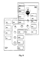
- FIG. 8 is a schematic view of a further embodiment of the position sensing switching device according to the invention.
- FIG. 1 is a general schematic view of a preferred embodiment of a position sensing switching device 1 according to the invention in the form of a gear-speed-changing unit for generating gear-speed-changing signals for an automatic gearbox.
- the position sensing switching device 1 has four switching units 2 and at least one activation unit 3 ., the activation unit 3 being displaceable with respect to the switching units 2 .
- the relative displacement of the switching units 2 and of the activation unit 3 with respect to one another takes place both in the horizontal and vertical directions. Displacement movements are thus understood both to be a pure displacement movement and a tilting movement.
- the switching units 2 are embodied as inductive sensor units and the activation unit 3 is embodied as an inductive damping unit whose method of operation is clarified using FIGS. 2 and 3 .
- FIG. 2 shows a preferred embodiment of one of the inductive switching units 2 .
- the inductive switching unit 2 is composed of an oscillating power source (Q ⁇ ) 11 , an exciter loop (E) 12 , a sensor loop (S) 13 , a voltage amplifier (V) 14 , an amplitude detector (D) 15 and an evaluation unit (A) 16 . All or some of the components 11 to 16 of the inductive switching unit 2 may be arranged on a printed circuit board 6 in a planar fashion.
- the exciter loop 12 is surrounded here by the sensor loop 13 , or vice versa.
- Exciters 12 such as the sensor loop 13 , can also be embodied with several windings.
- the inductive switching unit 2 functions as follows: the oscillating power source (Q ⁇ ) 11 impresses into the exciter loop 12 an electric current which alternates over time.
- the electric current generates a magnetic field M 1 which alternates over time and which has the field strength H 1 (x, y, z).
- the magnetic flux which alternates over time and which acts on the sensor coil 13 brings about a voltage in the sensor coil 13 , as in any electrical conductor, which is placed in the vicinity of the exciter coil 12 .
- the sensor voltage is amplified by the amplifier 1 a , the amplitude is determined with the detector 15 and the evaluation unit 16 compares it with a switching criterion K.
- FIG. 4 shows an example of the switching criterion K.
- the evaluation can be carried out by means of a comparator or a Schmitt trigger.
- the evaluation unit 16 for multiple switches is usually in the form of a microcontroller which passes on the switching information to control electronics or power electronics via an interface (CAN, LIN, etc.).
- FIG. 3 is a schematic view of the method of operation of the inductive switching unit 2 .
- a conductive layer, plate or loop is placed, as an activation unit (B) 3 in the vicinity of the exciter coil 12 , the magnetic field H 1 also penetrates this activation unit 3 and, according to Lenz, induces a voltage which brings about an eddy current I ks which flows in the opposite direction to the current in the exciter coil 12 .
- This short-circuit current which alternates over time generates a magnetic field M 2 which acts in opposition to M 1 , and, when the fields are superimposed on one another, this has an effect ranging from reducing to even extinguishing the entire magnetic field which penetrates the sensor coil 13 .
- This leads to a reduction in the sensor voltage and thus in the amplitude.
- This is compared with the switching criterion K by the evaluation unit 16 and triggers a switching function.
- the reduction in the sensor voltage by the actuator B can also be referred to as damping.
- the inductive damping unit can be constructed from materials with different degrees of electrical conductivity, for example from metal, from a conductive plastic etc.
- the damping is also dependent on the degree of overlap between the sensor loop 13 and the activation element 3 or the inductive damping unit. If the inductive damping unit overlaps the entire area of the outer loop 13 , the degree of coverage is 100% and the amplitude of the sensor signal is minimal. Two switching systems are therefore possible for the switch:
- the inductive switching unit 2 can also be extended to such an extent that one exciter coil 12 , surrounds a plurality of sensor coils 13 which are then connected to the amplifier via an analogue multiplexer AMUX. It is also conceivable to connect a plurality of exciter coils to the power source Q in a series connection, which exciter coils surround one or more sensor coils, such as is shown, for example in FIG. 5 .
- evaluation unit 16 in such a way that it does not trigger a switching function by comparison of the sensor voltage with a threshold value but rather triggers it additionally by comparison with the voltage of an adjacent sensor.
- the inductive switching unit 2 it is also possible to construct a pressure switch as follows.
- the activation unit 3 is mounted on a plunger which can alternately be locked in two positions similarly to a ballpoint pen mechanism. It is also conceivable to configure the mechanics of the pressure switch in such a way that the plunger does not have latching positions but can instead be displaced “freely” with respect to the switching unit or the sensor sliding plane. If the distance between the activation unit 3 and sensor sliding plane is, for example, 5 mm in the (latched) position P 1 and 0.5 mm in the (latched) position P 2 , a standardized amplitude voltage of approximately 0.5 must be set for the switching criterion K for the switching range shown in FIG. 3 .
- a pressure switch can also be embodied in such a way that a mechanism changes the degree of coverage G of the activator with respect to the sensor loop 13 .
- the sensor amplitude voltage then depends on the degree G of coverage and must be defined according to its characteristic curve.
- FIG. 6 shows, by way of example, what is referred to as a gate-type-gear changing unit such as is known generally as the prior art from the user's point of view.
- a gate-type-gear changing unit such as is known generally as the prior art from the user's point of view.
- inductive switches in conjunction with a gate-type-gear changing device is novel.
- These inductive switch designs are particularly expedient for a logic control, that is to say for a case in which the gear speeds in an automatic gearbox are not selected in a directly mechanical way.
- a printed circuit board 6 is positioned under the panel or cover 21 and, for example, the back lighting of the panel displays (“1”, “12” . . . , “P”) can be mounted on its upper side.
- An activator carriage (BS) 24 which rests in a planar fashion on the underside of the printed circuit board LP 6 , is connected to the gear lever automatic gear selector lever (AW) 22 , which dips through an opening 23 in the printed circuit board, one or more activation units 3 , for example two activation units BF 1 and BF 2 here, which can be displaced at a defined distance to the different inductive switching units (SE*) 2 , are provided on the activator carriage (BS) 24 .
- SE* inductive switching units
- the switching unit SE 5 which is represented in FIG. 1 , can be used to register a further switched position of the gear selector lever 22 .
- This switched position does not, however, occur in gear-speed-changing devices which are generally known from the prior art.
- the gear-speed-changing device 20 which is represented in FIG. 6I does not have any gear speed selector lever switched position corresponding to the switching unit SE 5 .
- This embodiment of the gear-speed changing device is thus optional, i.e. the switching unit SE 5 can be omitted.
- a current source 11 supplies the exciter coils 12 of a plurality of switching units (SE*) 4 .
- the signals of the sensor loops 13 of a plurality of switching units 2 are connected to the amplifier 14 via a wearfree semiconductor switch (AMUX).
- AMUX wearfree semiconductor switch
- the specification of which sensor unit is to be connected is received by AMUX from the evaluation unit 16 via the address specification AV.
- the evaluation unit 16 outputs the switched state as a function of the address specification.
- the associated sensor signal is damped as a function of the degree of overlap between the activator area of the activation unit 3 and the sensor unit (SE*) 4 . If the switching threshold SW of the signal which can be set at the evaluation unit 16 is reached, the position of the switch is detected as a valid position and switched over.
- An alternative to the previously proposed signal evaluation means with static threshold value comparison is to compare the sensor signals from two adjacent switching units 2 . If the signal of a switching unit 2 is lower than that of the adjacent switching unit 2 —in which case a hysteresis can also be taken into account, as illustrated in FIG. 7 —it is to be assumed that there is to be switching over from one position to the other. This results in switching thresholds being defined in a way which is very resistant to external influences such as temperature drifting of the amplifier 14 , of the power source 11 etc.
- the evaluation unit 16 should carry out the switching function in such a way that the entire system is placed in the safe state.
- the printed circuit board 6 can be equipped, for example, with safety switching units (SSE*) 2 , as is illustrated schematically in FIG. 8 .
- SSE* safety switching units
- the switching unit SE 5 and the corresponding safety switching unit SSE 5 can be used to register further positions of the gear selector lever 22 .
- gear speed-changing device 20 represented in FIG. 6 it is possible to omit such a switched position.
- a further embodiment of the position sensing switching device 1 according to the invention is obtained if, instead of pairs composed of one switching unit (SE*) 2 and one safety switching unit (SSE*) 2 , as is illustrated in FIG. 8 , just one switching unit 2 is used; for example instead of SSEP and SEP, only SSEP; instead of SSER and SER only SER; instead of SSEN and SEN only SSEN etc.
- the switching units 2 are accommodated relatively far apart from one another on the printed circuit board 6 .
- This structure of the position sensing switching device 1 makes it possible to avoid the undesired secondary damping effects which are caused by displacements of the activation units 3 .
Landscapes
- Engineering & Computer Science (AREA)
- General Engineering & Computer Science (AREA)
- Mechanical Engineering (AREA)
- Control Of Transmission Device (AREA)
- Measurement Of Length, Angles, Or The Like Using Electric Or Magnetic Means (AREA)
- Arrangement Or Mounting Of Control Devices For Change-Speed Gearing (AREA)
- Mechanical Control Devices (AREA)
- Amplifiers (AREA)
- Inductance-Capacitance Distribution Constants And Capacitance-Resistance Oscillators (AREA)
- Magnetically Actuated Valves (AREA)
- Gear-Shifting Mechanisms (AREA)
Applications Claiming Priority (2)
| Application Number | Priority Date | Filing Date | Title |
|---|---|---|---|
| DE10125278A DE10125278C2 (de) | 2001-05-23 | 2001-05-23 | Induktive Positionsschaltvorrichtung |
| DE10125278.1 | 2001-05-23 |
Publications (2)
| Publication Number | Publication Date |
|---|---|
| US20020175060A1 US20020175060A1 (en) | 2002-11-28 |
| US6852937B2 true US6852937B2 (en) | 2005-02-08 |
Family
ID=7685960
Family Applications (1)
| Application Number | Title | Priority Date | Filing Date |
|---|---|---|---|
| US10/141,799 Expired - Lifetime US6852937B2 (en) | 2001-05-23 | 2002-05-08 | Inductive position sensing switching device |
Country Status (5)
| Country | Link |
|---|---|
| US (1) | US6852937B2 (de) |
| EP (1) | EP1261131B1 (de) |
| JP (1) | JP2002351561A (de) |
| AT (1) | ATE426945T1 (de) |
| DE (2) | DE10125278C2 (de) |
Cited By (9)
| Publication number | Priority date | Publication date | Assignee | Title |
|---|---|---|---|---|
| US20040140890A1 (en) * | 2002-11-27 | 2004-07-22 | Robert Hartmann | Device for interrogating the locked condition of a vehicle safety belt buckle |
| US20050258687A1 (en) * | 2002-09-12 | 2005-11-24 | Martin Zapf | Inductive switch |
| US20080142346A1 (en) * | 2003-09-11 | 2008-06-19 | Cherry Gmbh | Inductive Switch |
| US20080157756A1 (en) * | 2006-11-22 | 2008-07-03 | Markus Eissner | Inductive position measuring device or goniometer |
| US20080238650A1 (en) * | 2007-03-30 | 2008-10-02 | Cherry Corp. | Configurable networked user interface and switch pack |
| US20100188104A1 (en) * | 2007-03-01 | 2010-07-29 | Christian Speckmann | Inductive incremental displacement sensor, method for determining the displacement of a first object relative to a second object, and inductive sensor unit |
| US20160187161A1 (en) * | 2013-08-13 | 2016-06-30 | Zf Friedrichshafen Ag | Sensor and method for detecting a position in two spatial directions |
| US20220123747A1 (en) * | 2020-10-15 | 2022-04-21 | Cherry Europe Gmbh | Apparatus comprising a movable object and a device for detecting a movement of the object, input device including the apparatus, and method of operating the apparatus |
| US20250091181A1 (en) * | 2020-02-24 | 2025-03-20 | Milwaukee Electric Tool Corporation | Impact tool |
Families Citing this family (11)
| Publication number | Priority date | Publication date | Assignee | Title |
|---|---|---|---|---|
| DE10319720B3 (de) * | 2003-05-02 | 2004-09-23 | Cherry Gmbh | Kulissenschalteinheit zur Erzeugung von Gangschaltsignalen für ein Automatik-Schaltgetriebe eines Kraftfahrzeuges |
| DE10335133A1 (de) | 2003-07-31 | 2005-03-03 | Pepperl + Fuchs Gmbh | Vorrichtung und Verfahren zur Erfassung des Wegs eines Zielobjektes |
| DE102004056800A1 (de) | 2004-11-24 | 2006-06-01 | Zf Friedrichshafen Ag | Schaltvorrichtung für ein Kraftfahrzeug |
| US7443159B2 (en) * | 2004-12-17 | 2008-10-28 | Cherry Gmbh | Sensor unit with staggered actuation faces |
| DE102006041934B4 (de) * | 2006-09-07 | 2017-05-04 | Werner Turck Gmbh & Co. Kg | Vorrichtung zur Bestimmung der Position eines Beeinflussungselementes |
| DE102008056698B4 (de) | 2008-11-11 | 2015-03-05 | Zf Friedrichshafen Ag | Wegmesssensor nach dem Helmholtzprinzip |
| JP5265035B2 (ja) * | 2012-04-03 | 2013-08-14 | 本田技研工業株式会社 | レバーポジション検出装置 |
| DE102015200619A1 (de) | 2015-01-16 | 2016-07-21 | Zf Friedrichshafen Ag | Induktive Positionsbestimmung |
| DE102016005826B4 (de) * | 2016-05-17 | 2020-07-16 | Pepperl+Fuchs Ag | Positionsmesseinheit und Positionsmessverfahren |
| DE102017212052A1 (de) * | 2017-07-13 | 2019-01-17 | Zf Friedrichshafen Ag | Induktive Positionsbestimmung |
| CN112526330B (zh) * | 2019-09-18 | 2025-09-09 | 法雷奥汽车内部控制(深圳)有限公司 | 开关位置检测方法以及开关位置检测装置 |
Citations (8)
| Publication number | Priority date | Publication date | Assignee | Title |
|---|---|---|---|---|
| DE6940505U (de) | 1969-09-19 | 1970-02-19 | Josef Eichberger | Warenautomat fuer zeitungen o.ae. |
| GB1452132A (en) | 1972-11-20 | 1976-10-13 | Cem Comp Electro Mec | Position detector |
| DE3619238A1 (de) | 1985-09-14 | 1987-03-26 | Turck Werner Kg | Naeherungsschalter |
| DE3734177A1 (de) | 1986-10-29 | 1988-05-05 | Baumer Electric Ag | Verfahren zur beruehrungslosen detektion von wirbelstrominduzierten koerpern, insbesondere von metallischen gegenstaenden, sowie auf das verfahren abgestuetzte sensoren |
| DE3735694A1 (de) | 1986-10-30 | 1988-05-11 | Ifm Electronic Gmbh | Elektronisches, beruehrungslos arbeitendes schaltgeraet |
| DE3743259A1 (de) | 1987-12-19 | 1989-06-29 | Kloeckner Humboldt Deutz Ag | Getriebefernschaltung, programmgesteuert fuer ein schleppergetriebe mit elektro-pneumatischer steuerung |
| US5198789A (en) * | 1991-07-25 | 1993-03-30 | Westinghouse Electric Corp. | Logic level electrical interlock device |
| DE19806529A1 (de) | 1998-02-17 | 1999-08-19 | Micro Epsilon Messtechnik | Weg-Winkel-Sensor |
Family Cites Families (9)
| Publication number | Priority date | Publication date | Assignee | Title |
|---|---|---|---|---|
| US4242676A (en) * | 1977-12-29 | 1980-12-30 | Centre Electronique Horloger Sa | Interactive device for data input into an instrument of small dimensions |
| GB2022264A (en) * | 1978-05-22 | 1979-12-12 | Gen Electric | High density capacitive touch switch array arrangement |
| DE3611862A1 (de) * | 1986-04-09 | 1987-10-15 | Steudler Gmbh & Co Kg A | Induktiver naeherungssensor |
| US5388476A (en) * | 1993-06-15 | 1995-02-14 | Agco Corporation | Gearshift mechanism |
| DE4335701C2 (de) * | 1993-10-20 | 1996-04-04 | Ifm Electronic Gmbh | Induktive Winkelmeßeinrichtung |
| DE19650154C2 (de) * | 1996-12-04 | 1999-06-10 | Lemfoerder Metallwaren Ag | Schaltvorrichtung für ein Getriebe eines KFZ mit einer mit Sensoren, Leuchtdioden, Prozessen und anderen elektronischen Bauelementen bestückten Leiterplatte und Verfahren zur Herstellung einer gekrümmten Leiterplatte zur Verwendung in einer solchen Schaltvorrichtung |
| DE19741367C1 (de) * | 1997-09-19 | 1999-02-25 | Siemens Ag | Elektrischer Schalter |
| DE10081559D2 (de) * | 1999-06-08 | 2002-08-14 | Luk Lamellen & Kupplungsbau | Verfahren zum Betreiben einer Getriebevorrichtung |
| DE60007270T2 (de) * | 2000-02-01 | 2004-09-02 | Cherry Gmbh | Position sensor |
-
2001
- 2001-05-23 DE DE10125278A patent/DE10125278C2/de not_active Expired - Fee Related
-
2002
- 2002-05-08 US US10/141,799 patent/US6852937B2/en not_active Expired - Lifetime
- 2002-05-17 DE DE50213376T patent/DE50213376D1/de not_active Expired - Lifetime
- 2002-05-17 AT AT02010271T patent/ATE426945T1/de not_active IP Right Cessation
- 2002-05-17 EP EP02010271A patent/EP1261131B1/de not_active Expired - Lifetime
- 2002-05-21 JP JP2002145783A patent/JP2002351561A/ja active Pending
Patent Citations (8)
| Publication number | Priority date | Publication date | Assignee | Title |
|---|---|---|---|---|
| DE6940505U (de) | 1969-09-19 | 1970-02-19 | Josef Eichberger | Warenautomat fuer zeitungen o.ae. |
| GB1452132A (en) | 1972-11-20 | 1976-10-13 | Cem Comp Electro Mec | Position detector |
| DE3619238A1 (de) | 1985-09-14 | 1987-03-26 | Turck Werner Kg | Naeherungsschalter |
| DE3734177A1 (de) | 1986-10-29 | 1988-05-05 | Baumer Electric Ag | Verfahren zur beruehrungslosen detektion von wirbelstrominduzierten koerpern, insbesondere von metallischen gegenstaenden, sowie auf das verfahren abgestuetzte sensoren |
| DE3735694A1 (de) | 1986-10-30 | 1988-05-11 | Ifm Electronic Gmbh | Elektronisches, beruehrungslos arbeitendes schaltgeraet |
| DE3743259A1 (de) | 1987-12-19 | 1989-06-29 | Kloeckner Humboldt Deutz Ag | Getriebefernschaltung, programmgesteuert fuer ein schleppergetriebe mit elektro-pneumatischer steuerung |
| US5198789A (en) * | 1991-07-25 | 1993-03-30 | Westinghouse Electric Corp. | Logic level electrical interlock device |
| DE19806529A1 (de) | 1998-02-17 | 1999-08-19 | Micro Epsilon Messtechnik | Weg-Winkel-Sensor |
Cited By (16)
| Publication number | Priority date | Publication date | Assignee | Title |
|---|---|---|---|---|
| US20050258687A1 (en) * | 2002-09-12 | 2005-11-24 | Martin Zapf | Inductive switch |
| US7633026B2 (en) * | 2002-09-12 | 2009-12-15 | Zf Friedrichshafen Ag | Inductive switch |
| US20040140890A1 (en) * | 2002-11-27 | 2004-07-22 | Robert Hartmann | Device for interrogating the locked condition of a vehicle safety belt buckle |
| US20080142346A1 (en) * | 2003-09-11 | 2008-06-19 | Cherry Gmbh | Inductive Switch |
| US7701201B2 (en) | 2003-09-11 | 2010-04-20 | Cherry Gmbh | Inductive switch |
| US20080157756A1 (en) * | 2006-11-22 | 2008-07-03 | Markus Eissner | Inductive position measuring device or goniometer |
| US7719263B2 (en) | 2006-11-22 | 2010-05-18 | Zf Friedrichshafen Ag | Inductive position measuring device or goniometer |
| US8508243B2 (en) * | 2007-03-01 | 2013-08-13 | Pepperl + Fuchs Gmbh | Inductive incremental displacement sensor, method for determining the displacement of a first object relative to a second object, and inductive sensor unit |
| US20100188104A1 (en) * | 2007-03-01 | 2010-07-29 | Christian Speckmann | Inductive incremental displacement sensor, method for determining the displacement of a first object relative to a second object, and inductive sensor unit |
| US20080238650A1 (en) * | 2007-03-30 | 2008-10-02 | Cherry Corp. | Configurable networked user interface and switch pack |
| US7791506B2 (en) | 2007-03-30 | 2010-09-07 | Zf Friedrichshafen Ag | Configurable networked user interface and switch pack |
| US20160187161A1 (en) * | 2013-08-13 | 2016-06-30 | Zf Friedrichshafen Ag | Sensor and method for detecting a position in two spatial directions |
| US20250091181A1 (en) * | 2020-02-24 | 2025-03-20 | Milwaukee Electric Tool Corporation | Impact tool |
| US20220123747A1 (en) * | 2020-10-15 | 2022-04-21 | Cherry Europe Gmbh | Apparatus comprising a movable object and a device for detecting a movement of the object, input device including the apparatus, and method of operating the apparatus |
| US11811399B2 (en) | 2020-10-15 | 2023-11-07 | Cherry Europe Gmbh | Keystroke detection device, keyboard, and keystroke detection method |
| US11817857B2 (en) | 2020-10-15 | 2023-11-14 | Cherry Europe Gmbh | Keystroke detection device, keyboard, and keystroke detection method |
Also Published As
| Publication number | Publication date |
|---|---|
| US20020175060A1 (en) | 2002-11-28 |
| ATE426945T1 (de) | 2009-04-15 |
| EP1261131A2 (de) | 2002-11-27 |
| EP1261131A3 (de) | 2005-11-16 |
| DE10125278C2 (de) | 2003-04-10 |
| EP1261131B1 (de) | 2009-03-25 |
| JP2002351561A (ja) | 2002-12-06 |
| DE50213376D1 (de) | 2009-05-07 |
| DE10125278A1 (de) | 2002-12-12 |
Similar Documents
| Publication | Publication Date | Title |
|---|---|---|
| US20020175060A1 (en) | Inductive position switching device | |
| US7633026B2 (en) | Inductive switch | |
| US7701201B2 (en) | Inductive switch | |
| US9318280B2 (en) | Contactless switch | |
| US8907661B2 (en) | Input apparatus with haptic feedback | |
| US6060969A (en) | Contactless proximity switch | |
| US7642673B2 (en) | Operating device for an electrical appliance and method for operating an electrical appliance | |
| US5424900A (en) | Electronic auxiliary contact for a contactor | |
| JP2021533490A (ja) | コンピュータ入力装置 | |
| CN1445635A (zh) | 用于电器用具的操作装置 | |
| US10965286B2 (en) | Remote-control system with homopolar magnets | |
| CA2522037A1 (en) | User interface for controlling a whirlpool tub | |
| US20080088397A1 (en) | Control mechanism with an operating lever and a bearing ball with integrated permanent magnet | |
| EP3136056B1 (de) | Positionssensor | |
| EP0943582A3 (de) | Positionsdetektor für Industriefahrzeuge | |
| US6965217B2 (en) | Tap changing assembly for power transformer | |
| US9347550B2 (en) | Shift lever device using magnetism detection switch | |
| US7369118B2 (en) | Magnetic oscillation metric controller | |
| KR100281512B1 (ko) | 포인팅기능을 갖는 원격 제어 송신기 | |
| CN220856409U (zh) | 一种非接触式旋钮开关及筋膜枪 | |
| KR20250074159A (ko) | 자석을 이용한 스위치 | |
| KR100475064B1 (ko) | 진공차단기의 온,오프 위치 감지장치 | |
| JPH074191U (ja) | 着脱式操作部を備えた電気装置 | |
| JP2018050393A (ja) | 開閉制御装置 | |
| WO2003016827A2 (en) | Circuit arrangement for controlling a magnetoresistive sensor |
Legal Events
| Date | Code | Title | Description |
|---|---|---|---|
| AS | Assignment |
Owner name: CHERRY GMBH, GERMANY Free format text: ASSIGNMENT OF ASSIGNORS INTEREST;ASSIGNORS:ZAPF, MARTIN;KUGLER, ALEXANDER;HAHN, GERHARD;REEL/FRAME:013097/0248;SIGNING DATES FROM 20020527 TO 20020612 |
|
| STCF | Information on status: patent grant |
Free format text: PATENTED CASE |
|
| FPAY | Fee payment |
Year of fee payment: 4 |
|
| AS | Assignment |
Owner name: ZF FRIEDRICHSHAFEN AG,, GERMANY Free format text: ASSIGNMENT OF ASSIGNORS INTEREST;ASSIGNOR:CHERRY GMBH;REEL/FRAME:022804/0046 Effective date: 20090427 |
|
| FPAY | Fee payment |
Year of fee payment: 8 |
|
| FPAY | Fee payment |
Year of fee payment: 12 |