US6891496B2 - Method and apparatus for physical layer radar pulse detection and estimation - Google Patents
Method and apparatus for physical layer radar pulse detection and estimation Download PDFInfo
- Publication number
- US6891496B2 US6891496B2 US10/138,953 US13895302A US6891496B2 US 6891496 B2 US6891496 B2 US 6891496B2 US 13895302 A US13895302 A US 13895302A US 6891496 B2 US6891496 B2 US 6891496B2
- Authority
- US
- United States
- Prior art keywords
- radar
- signal
- received signal
- pulse
- steps
- Prior art date
- Legal status (The legal status is an assumption and is not a legal conclusion. Google has not performed a legal analysis and makes no representation as to the accuracy of the status listed.)
- Expired - Fee Related
Links
Images


Classifications
-
- G—PHYSICS
- G01—MEASURING; TESTING
- G01S—RADIO DIRECTION-FINDING; RADIO NAVIGATION; DETERMINING DISTANCE OR VELOCITY BY USE OF RADIO WAVES; LOCATING OR PRESENCE-DETECTING BY USE OF THE REFLECTION OR RERADIATION OF RADIO WAVES; ANALOGOUS ARRANGEMENTS USING OTHER WAVES
- G01S13/00—Systems using the reflection or reradiation of radio waves, e.g. radar systems; Analogous systems using reflection or reradiation of waves whose nature or wavelength is irrelevant or unspecified
- G01S13/66—Radar-tracking systems; Analogous systems
-
- H—ELECTRICITY
- H04—ELECTRIC COMMUNICATION TECHNIQUE
- H04W—WIRELESS COMMUNICATION NETWORKS
- H04W16/00—Network planning, e.g. coverage or traffic planning tools; Network deployment, e.g. resource partitioning or cells structures
- H04W16/14—Spectrum sharing arrangements between different networks
-
- G—PHYSICS
- G01—MEASURING; TESTING
- G01S—RADIO DIRECTION-FINDING; RADIO NAVIGATION; DETERMINING DISTANCE OR VELOCITY BY USE OF RADIO WAVES; LOCATING OR PRESENCE-DETECTING BY USE OF THE REFLECTION OR RERADIATION OF RADIO WAVES; ANALOGOUS ARRANGEMENTS USING OTHER WAVES
- G01S7/00—Details of systems according to groups G01S13/00, G01S15/00, G01S17/00
- G01S7/02—Details of systems according to groups G01S13/00, G01S15/00, G01S17/00 of systems according to group G01S13/00
- G01S7/021—Auxiliary means for detecting or identifying radar signals or the like, e.g. radar jamming signals
-
- H—ELECTRICITY
- H04—ELECTRIC COMMUNICATION TECHNIQUE
- H04K—SECRET COMMUNICATION; JAMMING OF COMMUNICATION
- H04K3/00—Jamming of communication; Counter-measures
- H04K3/80—Jamming or countermeasure characterized by its function
- H04K3/82—Jamming or countermeasure characterized by its function related to preventing surveillance, interception or detection
- H04K3/822—Jamming or countermeasure characterized by its function related to preventing surveillance, interception or detection by detecting the presence of a surveillance, interception or detection
-
- H—ELECTRICITY
- H04—ELECTRIC COMMUNICATION TECHNIQUE
- H04K—SECRET COMMUNICATION; JAMMING OF COMMUNICATION
- H04K2203/00—Jamming of communication; Countermeasures
- H04K2203/10—Jamming or countermeasure used for a particular application
- H04K2203/18—Jamming or countermeasure used for a particular application for wireless local area networks or WLAN
-
- H—ELECTRICITY
- H04—ELECTRIC COMMUNICATION TECHNIQUE
- H04K—SECRET COMMUNICATION; JAMMING OF COMMUNICATION
- H04K3/00—Jamming of communication; Counter-measures
- H04K3/20—Countermeasures against jamming
- H04K3/22—Countermeasures against jamming including jamming detection and monitoring
- H04K3/224—Countermeasures against jamming including jamming detection and monitoring with countermeasures at transmission and/or reception of the jammed signal, e.g. stopping operation of transmitter or receiver, nulling or enhancing transmitted power in direction of or at frequency of jammer
- H04K3/226—Selection of non-jammed channel for communication
-
- H—ELECTRICITY
- H04—ELECTRIC COMMUNICATION TECHNIQUE
- H04W—WIRELESS COMMUNICATION NETWORKS
- H04W24/00—Supervisory, monitoring or testing arrangements
Definitions
- the present invention relates generally to data communications, and to a method and apparatus for identification of radar signals that may need to be avoided by the wireless system.
- Wireless Local Area Network (WLAN) devices must coexist with radar in the 5 GHz frequency bands. Interference mitigation techniques are required to enable WLAN devices to share these frequency bands with radar systems. The general requirement is that the WLAN devices detect interference, identify the radar interfering sources, and avoid using the frequencies used by the radar. Dynamic Frequency Selection (DFS) is used as a spectrum sharing mechanism by certain standards committees that define rules dictating the use of the 5 GHz space.
- DFS Dynamic Frequency Selection
- ETSI European Telecommunications Standards Institute
- BRAN Broadband Radio Access Networks
- transceiver equipment for use in HIPERLAN (High Performance Radio Local Area Networks) employ DFS mechanisms to detect interference from other systems, notably radar systems.
- One goal is to provide a uniform spread of equipment loading across a number of channels, such as fourteen channels of 330 MHz each, or 255 MHz each for equipment used in bands 5470 MHz to 5725 MHz.
- Present proposals from the ETSI BRAN committee provide various guidelines for radar detection. These include detecting and avoiding radar signals that only appear at a level above a certain pre-defined threshold, such as ⁇ 62 dBm. In one implementation, detection is based on a simple algorithm to see whether there are any instances of signals above the ⁇ 62 dBm threshold during a ten second startup listening period. Another proposed guideline is that detection during normal operation should be addressed by periodically suspending all network traffic and listening in startup mode for any instances of signals above the ⁇ 62 dBm threshold level.
- the present proposed methods of radar detection and avoidance are generally insufficient, especially in view of increased network traffic in the 5 GHz radio spectrum and the need for increased bandwidth among WLAN devices.
- the WLAN devices will need to quickly detect and avoid radar that have, among others, critical military, meteorological, and navigational functions. Therefore, additional detection and avoidance techniques are needed.
- an important aspect of any system is the ability to detect and distinguish radar signals from other traffic or interference that may also be present in the spectrum of the wireless device.
- the present inventors have realized the need to be able to reliably detect radar signals and distinguish them from packet collisions and other noise in wireless systems.
- the present invention provides a device and method for analyzing received signals to determine characteristics (parameters) of the received signal.
- the identified signal characteristics are forwarded to software or other electronics for processing to determine if the received signals are of a type that has priority in the band(s) which the signal was received, or, if the received signals are of a type which the wireless device should contend for the available spectrum. If the received signal has priority (e.g., commercial aviation, meteorological, law enforcement, military, or other specified radar and/or signal types), then, the wireless device(s) relinquish the spectrum. If the received signal is not one of the specified priority signals, the wireless device is free to relinquish or contend for the spectrum in whatever manner it deems appropriate.
- priority e.g., commercial aviation, meteorological, law enforcement, military, or other specified radar and/or signal types
- the present invention is mainly intended to detect and analyze radar signals to determine their characteristics, and particularly those signals operating in a same spectrum as a wireless LAN (WLAN) (e.g., 5 GHz).
- WLAN wireless LAN
- the devices and processes of the present invention may be configured for detection and analysis of other signals without restriction as to signal type, frequency, or implementation (e.g., WAN, LAN, peer to peer, etc.).
- the present invention provides a method of radar pulse detection, comprising the steps of, detecting a coarse gain drop in a receiver caused by a received signal, determining if the received signal is a radar pulse, and asserting a radar error if a coarse gain drop if of the received signal is due to a radar pulse.
- the present invention provides a method of radar detection, comprising the steps of, detecting an incoming signal having a signal strength greater than a radar threshold, processing a physical layer of a communication contained in the incoming signal, and asserting a radar error if an error occurs in the physical layer processing.
- the methods are performed simultaneously and combined as a method of radar detection, comprising the steps of, performing radar pulse detection on an incoming signal, performing a radar length detection on the incoming signal, and forwarding results of the radar pulse detection and radar length detection to an analysis device.
- the present invention may be embodied as a device for detecting radar signals, comprising, a signal strength detector configured to detect strength of received signals above a radar threshold, a communication processing device configured to perform processing on non-radar communication signals and assert error conditions if errors occur in the processing, a radar detector coupled to the signal strength detector and communication processing device and configured to assert a radar error if a received signal is above the radar threshold and a communications processing error occurs.
- any components of the present invention represented in a computer program, data sequences, and/or control signals may be embodied as an electronic signal broadcast (or transmitted) at any frequency in any medium including, but not limited to, wireless broadcasts, and transmissions over copper wire(s), fiber optic cable(s), and co-ax cable(s), etc.
- FIG. 1 is an illustration of an example wireless network in which the present invention is applied
- FIG. 2 is a block diagram of a radar detection device according to an embodiment of the present invention.
- FIG. 3 is a graph of a typical radar signal that may be transmitted in a same frequency spectrum as a wireless network and/or appliances of the wireless network;
- FIG. 4A is a graph of a short radar signal being detected by a wireless device configured according to an embodiment of the present invention
- FIG. 4B is a graph of a long radar signal being detected by a wireless device configured according to an embodiment of the present invention.
- FIG. 5 is a flow chart of a radar pulse detection process according to an embodiment of the present invention.
- FIG. 6 is a flow chart of a radar signal strength threshold detection process according to an embodiment of the present invention.
- FIG. 7 is a circuit block diagram of a radar detection circuit according to an embodiment of the present invention.
- a radar detection system illustrative of the present invention is now described. For purposes of explanation, numerous specific details are set forth in order to provide a thorough understanding of the present invention. It will be evident, however, to one of ordinary skill in the art, that the present invention may be practiced without these specific details.
- WLAN Wireless LAN
- Radio LAN Radio LAN
- the terms “Wireless LAN” and “Radio LAN” are used interchangeably to refer to a network for a device or devices that transmit in the 5 GHz space (e.g., IEEE 802.11a).
- a device could be an Access Point (AP), mobile terminal (node), or some other station within a greater wireless network.
- the wireless network device is configured to receive network traffic from other WLAN devices.
- the wireless network device can also receive unwanted signals from other sources, such as a radar source operating in the same frequency band(s). These signals may represent interference, or, may represent signals that must be avoided so that the wireless network device(s) do not interfere with them.
- ETSI currently promulgates a number of radar signals that must be avoided by a wireless device in order to be granted a license to operate in certain mostly unregulated portions of the spectrum.
- Table 1 provides an example listing of characteristics of ETSI identified radar signals:
- the characteristics of radar types identified in Table 1 provide identifying data that may be utilized to recognize certain radar signals. As it can be seen from the table, a number of radar sources need to be identified so that a wireless network device (or any wireless device) operating in that spectrum may take corrective action so as not to interfere with the priority signal (each ETSI identified signal is, for example, a priority signal).
- FIG. 1 illustrates a coverage area overlap and interference problems associated with a WLAN system.
- network 100 two independent sub-networks 103 and 105 are installed near to each other.
- access points (AP) 102 within their respective coverage areas, access points (AP) 102 (in sub-network 103 ) and 104 (in sub-network 105 ) each provide access to a fixed network such as an Ethernet LAN or an IEEE 1394 network.
- Each sub-network 103 and 105 also includes a number of mobile terminals (MT) (e.g. MT-D) wirelessly coupled to their respective network access points.
- MT mobile terminals
- Each mobile terminal can associate and dissociate with access points in the radio coverage area.
- the two radio coverage areas A and B are shown to overlap, thus illustrating the possibility of interference between the WLAN devices (mobile terminals and/or access points) in the coverage areas.
- the fixed networks for the access points are in general not the same, but may be coupled via a WAN, such as the Internet, or other communications link to allow coordination between the two independent coverage areas.
- Digital Frequency Selection (DFS) within each independent wireless network may be used to control the radio frequency to allow independent WLANs to coexist in overlapping zones.
- DFS techniques allow each access point to choose a frequency with sufficiently low interference; and other mechanisms, such as Transmission Power Control (TPC), reduces the range of interference from terminals, increasing spectral efficiency via more frequent channel re-use within a given geographic area.
- TPC Transmission Power Control
- a radar system comprising a radar source and receiver 106 operating in coverage area C 107 may also overlap one or more of the coverage areas operated by an access point.
- the radar source could be a fixed radar source, such as a radar transmitter, or it could be a mobile radar source, such as a weather radar installed in an airplane.
- the overlap between coverage area C 107 and coverage area B 103 illustrates potential WLAN traffic interference with radar signal reception at the radar source and receiver 106 .
- access point 102 includes a radar detection and avoidance system that enables the WLAN system 103 to detect the radar signals, identify the radar source 106 (e.g., via a signature, profile, or other analysis), and switch to a channel that the radar interference is not using.
- access point 102 includes a radar detection system that detects the presence of radar signals that have priority over access point 102 communications.
- the access point equipment and mobile terminals operate in the frequency ranges of 5.15 GHz to 5.35 GHz. This frequency range is generally divided into ten channels of 20 MHz each. Of these, typically eight are available for use by the access point. However, it should be understood that the present invention may be applied to other frequency ranges and devices.
- the access point WLAN device Upon initialization, for a given channel, the access point WLAN device tests for radar signals in the given channel and, if detected, switches to another channel, until it finds a channel free of radar signal traffic.
- the neighboring channels are also tested and are required to be free of certain radar signals.
- some radiolocation systems have bandwidth greater than one 802.11a channel. All of which allows the dynamic selection of frequencies within the 5 GHz frequency space to avoid interfering with the priority radar sources.
- events indicating a radar event such as a mobile radar entering a coverage area of the wireless network, are detected and continued operations of the wireless network are moved to a channel not occupied by the radar.
- each mobile device has its own coverage area (e.g., see mobile terminal D and its associated coverage area D 150 ), and the mobile devices themselves may also be configured to also detect radar events and initiate channel movement so as to not interfere with the radar.
- the present invention evaluates incoming signals to detect whether or not the received signal is a radar (or possibly another type of high priority signal). If the received signal is a radar, the characteristics of the received signal are sent to a processing device to determine if the radar signal is a signal that has priority for the channel.
- the detection of radar signals can occur on channels currently in use by a wireless device, channels that are intended to be used by a wireless device, or as a scanning device to determine an amount or character of radar traffic in a particular airspace.
- the present invention may be applied in a wireless device that avoids radar traffic on channels it is using or intends to use, and in monitoring devices that warn or otherwise provide information about radar signals within a vicinity or airspace being monitored (e.g., radar warning in combat aircraft, or automobiles, for example).
- FIG. 2 is a block diagram of a radar detection device according to an embodiment of the present invention.
- the detection is part of a wireless communication device 200 .
- the wireless communications device 200 transmits and receives wireless communications using RF wireless components (some of which are not shown for clarity), including components needed to implement radar detection according to the present invention.
- an RF generator 230 When the wireless device 200 is transmitting, an RF generator 230 generates RF signals (e.g., mixing an RF carrier frequency with IF frequency data 265 ). The RF signals are forwarded to the front end 220 for power amplification and then broadcast on antenna 210 .
- a transmit receive switch directs the signals to be broadcast to the power amplifier and/or antenna.
- antenna 210 When the wireless device is receiving, antenna 210 receives incoming signals for which it is tuned (e.g., 5 GHz space). The front end 220 amplifies received signals (e.g., LNA) to boost signal strength. Many other arrangements of switches, amplifiers, antennas, etc. may be utilized.
- received signals e.g., LNA
- the received signals are forwarded to a detector that processes the received signals to detect if they are radar. If the signals are radar, characteristics (parameters) of the received signal are forwarded to an analysis device 250 that determines if the radar should be avoided (e.g., the wireless device 200 needs to change channels). If the characteristics of the received signal cannot be affirmatively determined, estimates are produced and similarly forwarded.
- the detector 240 provides an important step in identifying radar signals by first detecting that the received signals are radar.
- the analysis device 250 includes programming or logic to identify or estimate priority signals and informs a tuner 260 to change the RF frequency.
- the tuner then acts to change the frequency of the RF signal produced by the RF generator 230 .
- the analysis device 250 sends a control signal to an alert device that produces an audio and/or visual warning signal to an operator (e.g., radar warning).
- the analysis device sends a message that is interpreted and displayed on a screen (e.g., a sweep radar style screen that identifies radar sources).
- a message e.g., containing data about the detected radar is sent to a database program that maintains a record of the traffic detected.
- FIG. 3 is a detailed graph of a typical radar signal 300 that may be transmitted in a same frequency spectrum as a wireless network and/or appliances of the wireless network.
- the radar signal 300 is an example of the type of signal that may be broadcast by radar source 106 in FIG. 1 , and consists of a series of pulses 302 , transmitted in a series of bursts, such as first burst 304 and second burst 306 . The bursts are separated by a gap 308 .
- Each radar signal pulse 302 is a high-frequency (approximately 5 GHz) wave (e.g., sine wave, square wave, etc.), and has a pulse duration (W) of approximately one microsecond to five microseconds (see Table 1 for more precise examples).
- W pulse duration
- the pulse period is the time between the start of consecutive pulses and is the inverse of a pulse repetition frequency (PRF) of the signal.
- the pulse period is typically on the order of one millisecond.
- the burst length (L) refers to the number of pulses in a burst or the time duration associated with the burst of pulses.
- the burst interval (P) is the time from the start of one burst to the start of the next consecutive burst, and is on the order of one second to ten seconds.
- the wireless communication device 200 of the access point listens for wireless LAN data packets. And, as described above, it is also configured to detect radar signals, such as illustrated in FIG. 3 while it is waiting to receive and respond to normal WLAN traffic. Upon detecting an event, the receiver analyzes the incoming signal to determine whether or not it is a regular WLAN packet. Various types of unrecognized events can be detected by the receiver. These include, noise fluctuations, collisions between WLAN stations or hidden nodes, co-channel interference, and other non-LAN wireless traffic, such as cordless phone transmissions, and the like.
- the typical radar signal possesses a degree of periodicity with respect to pulses and bursts.
- This characteristic is used by the receiver circuit 200 to differentiate noise and other types of anomalous (non-WLAN traffic) events from radar signals. Although noise may interfere and cause adverse effects on WLAN traffic, the access point need not be configured to strictly change channels when encountering noise, as opposed to radar, which may have priority for the channel.
- the event is analyzed with respect to periodicity, pulse characteristics, burst characteristics, and other parameters in a pattern-matching type of process to determine whether the event is a radar signal (priority signal) or not.
- Different types of radar systems and sources possess different pulse and burst characteristics.
- the system could be configured to classify any type of periodic event as a radar signal, or it could be configured to identify, to a certain degree of specificity, the identity of the radar source using look-up tables or profile data provided by system operators.
- the detector of the present invention provides a key determination on whether or not the received signals are radar, and, the analysis device then provides the final determination on whether or not the radar needs to be avoided or if the channel may be contended for by the WLAN device.
- information about the shape of the radar waveforms is not available, and only information such as that provided in Table 1 is used to distinguish noise and other traffic from the radar signals.
- the detector gathers information about the signal. For example, the detector determines the duration of the pulse, the magnitude of the pulse, and the separation of the pulse (e.g., via a time stamp). The detector also excludes certain signals by identifying the signal as part of another class of signals (e.g., IEEE 802.11a packets). The gathered information on the radar pulse is sent to the analysis device or software to attempt to establish the periodicity and the identity of the signals.
- False detects will occasionally occur because there is going to be noise that accidentally triggers the detection and analysis when the noise looks like a radar pulse having the characteristics which are being tested for.
- the system will accurately identify radar. For example, if the detector examines 23 pulses that are of a particular width and height, and separated by a particular length of time which is consistent with a predetermined radar, then the analysis device can find that pattern and affirmatively assert that a radar has been found.
- the present invention provides a method and device that gathers the pieces of information needed to identify a radar signal, without knowledge as to the actual shape of the radar signal waveform. That information is then forwarded for further processing and identification.
- AGC Automatic Gain Control
- a signal such as a radar signal
- the AGC has a significant amount of gain re-calibration (gain change) to perform in order to be able to effectively size the incoming signal.
- gain change gain change
- the present invention divides the tasks of information gathering into two parts, pulse detection and signal strength threshold detection.
- a pulse detection mechanism is provided for measuring and reporting that a signal came that was shorter than an amount of time needed by the AGC to properly size the incoming signal (generally, a couple micro seconds).
- the incoming signal e.g., pulses 304
- the pulse detection mechanism uses the amount of gain adjustment achieved to determine (estimate) the power of the incoming signal. Performed concurrently with pulse detection, signal strength threshold detection, or signal length detection, is useful when the incoming signal is actually long enough for the gain to be sufficiently adjusted and then various characteristics of the incoming signal ca be properly measured.
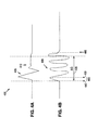
- FIG. 4A is a graph of a radar signal 400 being detected by a wireless device configured according to an embodiment of the present invention.
- the radar signal include a set of one or more main pulses (main pulses 405 ), and a small amount of residual signal 410 .
- An amount of time required to properly size the radar signal is illustrated as delta G 420 . In the delta G time frame, the radar signal pulse has completed, effectively leaving no signal for measurement after gain adjustment.
- FIG. 5 is a flow chart of a radar pulse detection process according to an embodiment of the present invention.
- a coarse gain drop at the AGC is an indication that an incoming signal is potentially a radar event.
- the incoming signal is monitored for an increase in power (e.g., a pulse).
- the increased power is indicated when the received signal goes out of a range of typical received signals. For example, average WLAN signals may be measured to determine a predetermined range of signal strengths and/or signal power. If the received signal exceeds that range, a coarse gain drop is triggered.
- a normally operating wireless device that encounters a 10-15 dB measured power increase in an ADC would also trigger a coarse gain drop.
- Gain adjustment, signal power, signal strength may be used individually or combined to trigger the coarse gain drop.
- the range of signal strengths and/or amount of dB gain drop in the ADC is user or manufacturer programmable.
- the present invention detects the arrival of an increase in power in the received signal.
- the preferred trigger is an increase in quantized power at the ADC, detected at the same time as a drop in gain.
- the in-band power of the incoming signal is measured (step 510 ).
- the in-band power is measured to determine if the pulse was in-band.
- the in-band power is measured before the gain is adjusted so that the pulse is not lost (short pulse) while the gain change is being made. Therefore, the present invention determines that a coarse gain drop is to be made, but then waits for the signal to go through the latency of the FIR (or other device from which the power is measured), and then measures the power (e.g., firpwr16) to determine if the same samples causing the coarse gain drop determination are in-band or out-of-band.
- the power measurement may not be exact because the signal may be clipping at the ADC, but it will give data sufficient to at least estimate whether the signal was in-band or out-of-band.
- the measurement of in-band signal power is performed, for example, by measuring power at an FIR filter or other mechanisms in the receiver.
- the gain setting is saved for later comparison calculations.
- the gain is then adjusted based on the measured signal power as normally occurs (step 520 ). With each gain adjustment the current gain setting becomes closer to an amount of gain needed to properly size the incoming signal. If the signal is very short, only one gain adjustment will be made, and then, because the signal is gone, the gain will be adjusted back to a level that is properly quantized (sized) for ambient noise in the band being received.
- the measured power of the signal and gain parameters are used to determine if the received signal is a pulse (step 525 ).
- a pulse is defined as an in-band signal having a maximum power greater than a radar pulse threshold, and, after the gain has been properly quantized, the received signal strength (RSSI) is less than the RSSI of the signal that caused the coarse gain drop. If no pulse is detected, the incoming signal is processed normally (move on to correlation and physical level tests) without asserting any radar conditions.
- a radar condition (or error) is asserted with a length equal to zero because the pulse was too short to make a measurement. (step 535 ). The process then returns and waits for a next coarse gain drop.
- Signal confirmation means the received signal appears to contain a non-radar communication consistent with the type of communication a device implementing the present invention expects to receive in the normal course of communications.
- the present invention does not have strict criteria for determining that the signal might be a normal communication, particularly with large and in-band signals which are sized correctly and then passed along the receiver chain as soon as possible. In these cases, phy errors (physical layer processing errors) in the receiver reject the packet if it isn't a normal communication.
- PHY error physical layer testing
- the number of gain adjustments made provides a length value that is also forwarded to the analysis device.
- gain adjustment counting is not a fully precise measurement technique, the data it provides can be used as evidence to help the analysis device make a decision on whether or not to assert a radar condition.
- Table 2 provides an example set of pseudo code implementing a pulse detection process according to an embodiment of the present invention. As with all the pseudo code listings provided herein, this listing is not intended to be a compilable or executable section of code, but is intended as an example programming structure that may be utilized to implement a program consistent with the discussions herein.
- each of the variables utilized, particularly the threshold values are programmable at either a manufacturing stage (set-up) of components in, or by an end user of (e.g., via a GUI or other interface), a device according to the present invention.
- PHY error physical level error
- the gain remains at a same setting and the received power of the potential radar signal continues to be measured until it drops by a significant amount (e.g., a 10 dB drop in received power) indicating that the signal has stopped.
- the time span between initial reception of the signal and the received power drop is calculated as a duration which is then passed on to the analysis device 250 .
- FIG. 4B is a graph of a long radar signal 420 being detected by a wireless device configured according to an embodiment of the present invention.
- the long radar signal 430 is different from the radar pulse signal 400 because it is of longer duration. The longer duration provides the detector more time to gather information about the radar signal.
- the long radar signal 420 extends beyond the amount of time required for a gain control mechanism to properly size the incoming signal ( ⁇ G, 420 )
- FIG. 6 is a flow chart of a radar signal length detection process according to an embodiment of the present invention. The process is utilized when a received signal is long enough for a gain control mechanism to size the received signal.
- a received signal strength (RSSI) is compared to a radar signal strength threshold. If the RSSI exceeds the radar signal strength threshold, then a counter is initialized (step 610 ).
- the counter is initialized at point 450 .
- the counter is initialized with a count value approximately equal to an amount of time ( 445 ) that represents time required to register RSSI, set the counter, or other factors that need to be accounted for in a timing indicated by the counter value.
- the counter is initialized to zero and adjustments (if needed) are made at some point after the counter value is read.
- the counter indicates a length of the incoming signal.
- the counter is stopped.
- the counter value indicates the size of the signal (e.g., point 440 to just prior to point 460 ). If a phy error is detected (step 640 ), then a radar error is asserted with a length equivalent to the counter value (step 645 ). If no phy error occurs, which indicates a valid data communication, the incoming signal (e.g., an IEEE 802.11a packet) is processed normally (step 650 ).
- a number of different mechanisms may be utilized to determine a phy error in the incoming signal. For example, preamble testing, self correlation of short sequences, signal field/data signal checks, transition to long sequences, self correlation of long sequences, parity checks, or testing certain allowable values for particular fields or lengths of fields.
- McFarland et al. application Ser. No. 09/963,217, entitled “METHOD AND SYSTEM FOR DETECTING FALSE PACKETS IN WIRELESS COMMUNICATIONS SYSTEMS,” filed Sep. 25, 2001, the contents of which are incorporated herein by reference in its entirety, discloses a number of field and value checks that may be applied to physical level testing of incoming data packets.
- phy errors occur because of a bad packet, packet collisions, no packet, and/or noise.
- a phy error combined with a large gain drop indicates a radar signal.
- a radar error is asserted and the length of the radar signal (e.g., counter value) is sent on the analysis device.
- step 620 If no power drop occurs at step 620 , and no PHY errors are encountered (step 655 ), a normal packet is being received and it is processed normally (step 650 ). However, if no power drop occurs initially (step 620 ), and a PHY error is encountered, then a radar signal is most likely being received.
- a delay is initiated.
- the delay is a wait period approximately equivalent to the longest known radar signal (or longest priority signal). Some additional wait time may be included in the wait period to account for system response.
- the delay period assures that an opportunity exists to detect a power drop in the radar signal even if the longest radar signal is being received.
- a power drop is detected (step 670 )
- a radar error is asserted and the counter value is sent on to the analysis device (step 657 ).
- a time out of the delay period occurs (step 680 ), a radar condition is asserted with a default length which is passed on to the analysis device.
- the default length is, for example, a length greater than any of the known radars (or other code identifying default radar identification).
- the analysis device uses the information that a longer than known radar detection has occurred in its analysis to determine type of radar (or other signal) has been received.
- Table 3 is an example set of pseudo code implementing a signal length detection process according to an embodiment of the present invention:
- FIG. 7 is a circuit block diagram of a radar detection circuit 700 according to an embodiment of the present invention.
- Antenna 705 is tuned, for example, to the 5 GHz band.
- Received signals are processed by an analog front end 710 .
- the analog front end can be any arrangement of power amplifiers, LNA's or other devices known in the art.
- Some example implementations of RF front end devices are described in Zargari, U.S. Pat. No. 6,351,502, application Ser. No. 09/483,948, entitled “RF FRONT-END WITH MULTISTAGE STEPDOWN FILTERING ARCHITECTURE,” filed Jan. 13, 2000, the contents of which are incorporated herein by reference in their entirety.
- the ordinarily skilled artisan will be capable of utilizing any one of the RF front end devices described in Zagari, or others, to work with the present invention.
- Analog to digital converter (ADC) 715 digitizes the received signal as conditioned by the analog front end 710 .
- the digital signal is then split for filtering (FIR 1 720 ) and decoding.
- the split signal has additional filtering (FIR 2 730 ).
- An amount of power of the filtered signal is calculated by power calculator 735 .
- the power calculator 735 is, for example, a sum (I 2 +Q 2 ) device.
- a power in the signal more directly from the ADC 715 is also calculated by power device 765 .
- ADC power indicates if the signal is in-band (approximately equivalent ADC and FIR power indicates an in-band signal, while significant variations in ADC and FIR power indicate the signal may be spillover from a nearby band, which indicates a non in-band WLAN signal).
- AGC Automatic Gain Control
- the AGC also performs comparisons of the ADC power and FIR power and provides that information to the detection device for further processing as discussed elsewhere herein.
- the detection device is implemented in software by a processor coupled to the AGC, but may also be implemented in hardware using integrated or discrete components alone or combined with other parts.
- a self correlation unit 740 is also shown that performs correlation functions to synch up with incoming packets.
- Various embodiments of AGC and self-correlation may be utilized. Husted et al., entitled “IN-BAND AND OUT-OF-BAND SIGNAL DETECTION FOR AUTOMATIC GAIN CALIBRATION SYSTEMS,” application Ser. No. 09/849,442, Client Docket No. ATH-044, filed May 4, 2001, and Husted et al. II, “SELF-CORRELATION DETECTION IN AUTOMATIC GAIN CALIBRATION,” application Ser. No. 09/849,595, Client Docket No. ATH-045, filed May 4, 2001, the contents of which are incorporated herein by reference in their entirety, discuss a number of embodiments and processes for AGC and self-correlation that may be used in a device according to the present invention.
- FIG. 7 includes downsamplers 755 and 720 (contained in FIR 1 ) that allow operation in different modes (here, configured for operation in standard mode or Atheros Turbo mode). Other modes of operation may also be accommodated with similar switching arrangements.
- the present invention is mainly intended to detect radar (or other) signals that should be avoided, other implementations of the technology described are also clearly practical. For example, avoiding signals in-band for performance reasons.
- the no traffic band is chosen to transmit in, even if the traffic signals didn't have priority in the first band.
- the present invention includes a computer program product which is a storage medium (media) having instructions stored thereon/in which can be used to control, or cause, a computer to perform any of the processes of the present invention.
- the storage medium can include, but is not limited to, any type of disk including floppy disks, mini disks (MD's), optical discs, DVD, CD-ROMS, micro-drive, and magneto-optical disks, ROMs, RAMs, EPROMs, EEPROMs, DRAMs, VRAMs, flash memory devices (including flash cards), magnetic or optical cards, nanosystems (including molecular memory ICs), RAID devices, remote data storage/archive/warehousing, or any type of media or device suitable for storing instructions and/or data.
- the present invention includes software for controlling both the hardware of the general purpose/specialized computer or microprocessor, and for enabling the computer or microprocessor to interact with a human user or other mechanism utilizing the results of the present invention.
- software may include, but is not limited to, device drivers, operating systems, and user applications.
- computer readable media further includes software for performing the present invention, as described above.
- the programming (software) of the general/specialized computer or microprocessor are software modules for implementing the teachings of the present invention, including, but not limited to, identification of received signal strength, adjusting gain, self-correlation, physical layer processing, asserting radar conditions and events (radar detection), and forwarding radar lengths, signal characteristics, and other radar indications to other modules for further processing, applying these processes to an entire system that identifies specific radar signals and changes channels of a wireless device operating on a same channel as the detected radar signal, and the display, storage, or communication of results according to the processes of the present invention.
- software modules for implementing the teachings of the present invention, including, but not limited to, identification of received signal strength, adjusting gain, self-correlation, physical layer processing, asserting radar conditions and events (radar detection), and forwarding radar lengths, signal characteristics, and other radar indications to other modules for further processing, applying these processes to an entire system that identifies specific radar signals and changes channels of a wireless device operating on a same channel as the detected radar signal, and the display
Landscapes
- Engineering & Computer Science (AREA)
- Radar, Positioning & Navigation (AREA)
- Remote Sensing (AREA)
- Computer Networks & Wireless Communication (AREA)
- Signal Processing (AREA)
- Physics & Mathematics (AREA)
- General Physics & Mathematics (AREA)
- Mobile Radio Communication Systems (AREA)
- Radar Systems Or Details Thereof (AREA)
- Monitoring And Testing Of Transmission In General (AREA)
Priority Applications (9)
| Application Number | Priority Date | Filing Date | Title |
|---|---|---|---|
| US10/138,953 US6891496B2 (en) | 2002-05-03 | 2002-05-03 | Method and apparatus for physical layer radar pulse detection and estimation |
| US10/406,756 US6954171B2 (en) | 2002-05-03 | 2003-04-02 | Method and apparatus for physical layer radar pulse detection and estimation |
| TW092112138A TWI242078B (en) | 2002-05-03 | 2003-05-02 | Method and apparatus for physical layer radar pulse detection and estimation |
| AU2003243203A AU2003243203A1 (en) | 2002-05-03 | 2003-05-02 | Method and apparatus for radar pulse detection and estimation in wireless lan physical layer |
| KR1020047017471A KR100990538B1 (ko) | 2002-05-03 | 2003-05-02 | 무선 lan 물리층에서 레이더 펄스를 탐지 및 추정하기위한 방법 및 장치 |
| PCT/US2003/014260 WO2003093860A1 (en) | 2002-05-03 | 2003-05-02 | Method and apparatus for radar pulse detection and estimation in wireless lan physical layer |
| AT03747675T ATE514100T1 (de) | 2002-05-03 | 2003-05-02 | Verfahren und vorrichtung zur radarimpulsdetektion und -schätzung in der physischen schicht eines drahtlosen lan |
| EP03747675A EP1502126B1 (de) | 2002-05-03 | 2003-05-02 | Verfahren und vorrichtung zur radarimpulsdetektion und -schätzung in der physischen schicht eines drahtlosen lan |
| US10/884,785 US7129884B1 (en) | 2002-05-03 | 2004-07-01 | Multiple antenna radar signal detection and estimation |
Applications Claiming Priority (1)
| Application Number | Priority Date | Filing Date | Title |
|---|---|---|---|
| US10/138,953 US6891496B2 (en) | 2002-05-03 | 2002-05-03 | Method and apparatus for physical layer radar pulse detection and estimation |
Related Child Applications (2)
| Application Number | Title | Priority Date | Filing Date |
|---|---|---|---|
| US10/406,756 Division US6954171B2 (en) | 2002-05-03 | 2003-04-02 | Method and apparatus for physical layer radar pulse detection and estimation |
| US10/884,785 Continuation-In-Part US7129884B1 (en) | 2002-05-03 | 2004-07-01 | Multiple antenna radar signal detection and estimation |
Publications (2)
| Publication Number | Publication Date |
|---|---|
| US20030214430A1 US20030214430A1 (en) | 2003-11-20 |
| US6891496B2 true US6891496B2 (en) | 2005-05-10 |
Family
ID=29269471
Family Applications (3)
| Application Number | Title | Priority Date | Filing Date |
|---|---|---|---|
| US10/138,953 Expired - Fee Related US6891496B2 (en) | 2002-05-03 | 2002-05-03 | Method and apparatus for physical layer radar pulse detection and estimation |
| US10/406,756 Expired - Fee Related US6954171B2 (en) | 2002-05-03 | 2003-04-02 | Method and apparatus for physical layer radar pulse detection and estimation |
| US10/884,785 Expired - Fee Related US7129884B1 (en) | 2002-05-03 | 2004-07-01 | Multiple antenna radar signal detection and estimation |
Family Applications After (2)
| Application Number | Title | Priority Date | Filing Date |
|---|---|---|---|
| US10/406,756 Expired - Fee Related US6954171B2 (en) | 2002-05-03 | 2003-04-02 | Method and apparatus for physical layer radar pulse detection and estimation |
| US10/884,785 Expired - Fee Related US7129884B1 (en) | 2002-05-03 | 2004-07-01 | Multiple antenna radar signal detection and estimation |
Country Status (7)
| Country | Link |
|---|---|
| US (3) | US6891496B2 (de) |
| EP (1) | EP1502126B1 (de) |
| KR (1) | KR100990538B1 (de) |
| AT (1) | ATE514100T1 (de) |
| AU (1) | AU2003243203A1 (de) |
| TW (1) | TWI242078B (de) |
| WO (1) | WO2003093860A1 (de) |
Cited By (25)
| Publication number | Priority date | Publication date | Assignee | Title |
|---|---|---|---|---|
| US20040033789A1 (en) * | 2002-08-19 | 2004-02-19 | Tsien Chih C. | Dynamic frequency selection and radar detection with a wireless LAN |
| US20040151137A1 (en) * | 2003-01-30 | 2004-08-05 | Atheros Communications, Inc. | Methods for implementing a dynamic frequency selection (DFS) feature for WLAN devices |
| US20050113031A1 (en) * | 2003-06-11 | 2005-05-26 | Kensington Technology Group | Systems and methods for a wireless network connection point locator |
| US20060199587A1 (en) * | 2003-09-15 | 2006-09-07 | Broadcom Corporation, A California Corporation | Radar detection circuit for a WLAN transceiver |
| US20060258296A1 (en) * | 2005-05-12 | 2006-11-16 | David Steer | Method and system for detecting radar signals |
| US20070025736A1 (en) * | 2005-07-28 | 2007-02-01 | Microsoft Corporation | Compensating for errors received in a signal |
| US20070082691A1 (en) * | 2005-09-29 | 2007-04-12 | Trainin Solomon B | System, method and device of radar detection |
| US20070188376A1 (en) * | 2004-08-03 | 2007-08-16 | Theobold David M | Radar protection device for wireless networks |
| US20070216570A1 (en) * | 2006-03-02 | 2007-09-20 | Motorola, Inc. | Method and apparatus for signal detection |
| US20070281638A1 (en) * | 2003-09-15 | 2007-12-06 | Broadcom Corporation | Radar detection circuit for a wlan transceiver |
| US20080211712A1 (en) * | 2007-01-22 | 2008-09-04 | Nils Bagge | Detecting and recognizing long duration waveforms |
| US20090028097A1 (en) * | 2007-07-25 | 2009-01-29 | Patel Vijaykumar M | Dynamic frequency selection in wireless devices |
| US20090160696A1 (en) * | 2007-12-21 | 2009-06-25 | Ralink Technology Corporation | Configurable radar detection and avoidance system for wireless ofdm tranceivers |
| US20100091670A1 (en) * | 2008-10-10 | 2010-04-15 | Ralink Technology (Singapore) Corporation | Method and apparatus to allow coeixtence between wireless devices |
| US20100123835A1 (en) * | 2008-11-19 | 2010-05-20 | Oki Semiconductor Co., Ltd. | Radio lsi device and interfering wave detecting circuit |
| US7848219B1 (en) | 2007-08-07 | 2010-12-07 | Atheros Communications, Inc. | Radar detection for wireless communication devices |
| US7929508B1 (en) | 2008-06-11 | 2011-04-19 | Atheros Communications, Inc. | Radio frequency signal analysis and classification using time-frequency information |
| US20130128927A1 (en) * | 2011-11-18 | 2013-05-23 | Qualcomm Atheros, Inc. | System and method for detecting chirping radar pulses |
| US20130314267A1 (en) * | 2012-05-24 | 2013-11-28 | Thomas J. Kenney | Multi-band scanning for radar detection in wi-fi systems |
| US9550583B2 (en) | 2015-03-03 | 2017-01-24 | Honeywell International Inc. | Aircraft LRU data collection and reliability prediction |
| US9854461B2 (en) | 2007-08-15 | 2017-12-26 | Shared Spectrum Company | Methods for detecting and classifying signals transmitted over a radio frequency spectrum |
| US10484927B2 (en) | 2006-12-29 | 2019-11-19 | Shared Spectrum Company | Method and device for policy-based control of radio |
| US20240103160A1 (en) * | 2022-09-28 | 2024-03-28 | DC-001, Inc. dba Spartan Radar | Systems and methods for scheduling radar scan patterns in a vehicular radar system |
| US12571909B2 (en) | 2022-09-28 | 2026-03-10 | Deere & Company | Systems and methods for controlling the operation of a vehicular radar system |
| US12613327B1 (en) | 2023-01-23 | 2026-04-28 | Deere & Company | Systems and methods for prioritizing detected objects in a vehicular radar system |
Families Citing this family (75)
| Publication number | Priority date | Publication date | Assignee | Title |
|---|---|---|---|---|
| AT411991B (de) | 1998-11-18 | 2004-08-26 | Steco Logistic Gmbh | Behälter aus mehreren platten |
| KR20040026798A (ko) * | 2002-09-26 | 2004-04-01 | 주식회사 케이티 | 무선 근거리통신망 시스템의 패킷수신 제어 방법 |
| US7107032B2 (en) * | 2003-01-08 | 2006-09-12 | Mediatek Inc. | Radar detection method for radio local area networks |
| US6870815B2 (en) * | 2003-01-30 | 2005-03-22 | Atheros Communications, Inc. | Methods for implementing a dynamic frequency selection (DFS) and a temporary channel selection feature for WLAN devices |
| SE0301835L (sv) * | 2003-06-24 | 2005-02-01 | Infineon Technologies Ag | Förfarande och anordning för att minska den genomsnittliga tiden som behövs för en kommunikationsenhet att ansluta sig till ett kommunikationsnätverk |
| SE0301836D0 (sv) * | 2003-06-24 | 2003-06-24 | Infineon Technologies Ag | Detection apparatus and method |
| US8014787B2 (en) * | 2003-08-07 | 2011-09-06 | Agere Systems Inc. | System and method for discriminating radar transmissions from wireless network transmissions and wireless network having radar-avoidance capability |
| JP3828546B2 (ja) * | 2004-01-26 | 2006-10-04 | 株式会社東芝 | 無線通信装置、無線通信方法及び無線通信プログラム |
| US7280067B2 (en) * | 2004-06-01 | 2007-10-09 | Newlogic Technologies Gmbh | Radar detector and radar detecting method for WLAN systems according to 802.11 wireless communication standards |
| US20060082489A1 (en) * | 2004-10-15 | 2006-04-20 | Liu Jiewen J | Radar presence alert for WLAN |
| WO2006107565A1 (en) * | 2005-04-04 | 2006-10-12 | Raytheon Company | System and method for coherently combining a plurality of radars |
| KR101189817B1 (ko) | 2005-08-08 | 2012-10-10 | 마벨 월드 트레이드 리미티드 | 레이더 검출 장치 및 그 방법 |
| US7599671B2 (en) * | 2005-08-08 | 2009-10-06 | Marvell World Trade Ltd. | Radar detection apparatus and method thereof |
| US7548750B2 (en) * | 2005-09-13 | 2009-06-16 | Cisco Technology, Inc. | System and method for detection of primary spectrum users |
| US8873470B2 (en) * | 2005-09-16 | 2014-10-28 | Koninklijke Philips N.V. | Method of recovering communication access in dynamic spectrum access wireless systems |
| US20080219201A1 (en) * | 2005-09-16 | 2008-09-11 | Koninklijke Philips Electronics, N.V. | Method of Clustering Devices in Wireless Communication Network |
| EP1988403A3 (de) | 2005-10-24 | 2011-03-23 | Mitsubishi Electric Information Technology Centre Europe B.V. | Analyse von Impulszügen |
| US7702044B2 (en) * | 2005-12-05 | 2010-04-20 | Marvell World Trade, Ltd. | Radar detection and dynamic frequency selection |
| US7747222B2 (en) * | 2005-12-09 | 2010-06-29 | Marvell World Trade Ltd. | Detection and estimation of radio frequency variations |
| KR101235801B1 (ko) * | 2006-03-08 | 2013-02-21 | 삼성전자주식회사 | 5GHz를 사용하는 무선 랜에서 레이더 신호를 검출하는방법 및 장치 |
| US8542638B2 (en) * | 2006-04-20 | 2013-09-24 | Microchip Technology Incorporated | System and method for interference identification and frequency allocation |
| KR100772417B1 (ko) * | 2006-09-26 | 2007-11-01 | 삼성전자주식회사 | 다이렉트 링크를 이용한 무선네트워크 통신 방법 및 그장치 |
| US8139496B2 (en) | 2007-03-06 | 2012-03-20 | Spectrum Bridge, Inc. | System and method for policing spectrum usage |
| US7596461B2 (en) * | 2007-07-06 | 2009-09-29 | Cisco Technology, Inc. | Measurement of air quality in wireless networks |
| EP2015459A1 (de) * | 2007-07-12 | 2009-01-14 | STMicroelectronics N.V. | Verfahren zum Erkennen der eventuellen Anwesenheit eines Störsignals, beispielsweise eines Radarsignals, das eine drahtlose Vorrichtung stören kann, beispielsweise eine Ultrabreitbandvorrichtung, und entsprechende Vorrichtung |
| JP4575409B2 (ja) | 2007-08-22 | 2010-11-04 | 株式会社東芝 | 無線通信装置 |
| US8310967B1 (en) | 2008-06-19 | 2012-11-13 | Marvell International Ltd. | Infrastructure and ad-hoc node device |
| US20100042350A1 (en) * | 2008-08-12 | 2010-02-18 | Certrite Llc | Doppler radar gun certification system |
| US9288764B1 (en) * | 2008-12-31 | 2016-03-15 | Marvell International Ltd. | Discovery-phase power conservation |
| US8305971B2 (en) * | 2009-01-13 | 2012-11-06 | Cisco Technology, Inc. | Utilizing persistent interference information for radio channel selection |
| US8472427B1 (en) | 2009-04-06 | 2013-06-25 | Marvell International Ltd. | Packet exchange arbitration for coexisting radios |
| US20100296554A1 (en) * | 2009-05-19 | 2010-11-25 | Ralink Technology (Singapore) Corporation | Method and system for detecting data from multiple antennas |
| US8340034B1 (en) | 2009-11-11 | 2012-12-25 | Marvell International Ltd. | Bluetooth and wireless LAN arbitration |
| US9132773B2 (en) | 2009-12-07 | 2015-09-15 | Cobra Electronics Corporation | Mobile communication system and method for analyzing alerts associated with vehicular travel |
| RU2515465C2 (ru) * | 2009-12-07 | 2014-05-10 | Кобра Электроникс Корпорейшн | Способ анализирования данных, полученных от объединенных детекторов радаров |
| US9848114B2 (en) | 2009-12-07 | 2017-12-19 | Cobra Electronics Corporation | Vehicle camera system |
| KR101710469B1 (ko) * | 2009-12-17 | 2017-02-28 | 삼성전자주식회사 | 레이더 신호를 검출하기 위한 방법 |
| JP2013515325A (ja) | 2009-12-22 | 2013-05-02 | コブラ エレクトロニクス コーポレーション | モバイル通信デバイスとインターフェースするレーダ検出装置 |
| US8576817B2 (en) | 2010-04-08 | 2013-11-05 | Spectrum Bridge, Inc. | System and method for managing radio access to spectrum and to a spectrum management system |
| US8767771B1 (en) | 2010-05-11 | 2014-07-01 | Marvell International Ltd. | Wakeup beacons for mesh networks |
| EP2630827B1 (de) | 2010-10-20 | 2018-11-21 | Marvell World Trade Ltd. | Dienst-entdeckung vor assoziierung |
| JP5719192B2 (ja) * | 2011-02-17 | 2015-05-13 | 株式会社Nttドコモ | 無線局、干渉回避方法及びシステム |
| US8644868B2 (en) | 2011-03-07 | 2014-02-04 | Spectrum Bridge, Inc. | System and method for managing spectrum allocation |
| US8750278B1 (en) | 2011-05-26 | 2014-06-10 | Marvell International Ltd. | Method and apparatus for off-channel device invitation |
| US8948801B2 (en) | 2011-08-03 | 2015-02-03 | Spectrum Bridge, Inc. | Systems and methods for provisioning and allocating a commoditized spectrum object |
| US8831625B2 (en) | 2011-08-03 | 2014-09-09 | Spectrum Bridge, Inc. | Systems and methods for processing spectrum coexistence information to optimize spectrum allocation |
| US9125216B1 (en) | 2011-09-28 | 2015-09-01 | Marvell International Ltd. | Method and apparatus for avoiding interference among multiple radios |
| US9036517B2 (en) | 2012-01-09 | 2015-05-19 | Marvell World Trade Ltd. | Methods and apparatus for establishing a tunneled direct link setup (TDLS) session between devices in a wireless network |
| KR101300595B1 (ko) * | 2012-03-06 | 2013-08-28 | (주)아이앤씨테크놀로지 | 무선 통신 장치 및 이의 레이더 신호 검출 방법 |
| US9609676B1 (en) | 2012-03-30 | 2017-03-28 | Marvell International Ltd. | Efficient transition from discovery to link establishment |
| US8660219B2 (en) | 2012-04-03 | 2014-02-25 | Summit Semiconductor Llc | Circuit and method for distinguishing between an OFDM signal and a radar signal |
| EP2842381B1 (de) * | 2012-04-23 | 2017-09-06 | Intel Corporation | Systeme und verfahren zur interferenzunterdrückung für eine peer-to-peer-netzwerkverbindung |
| US9279881B2 (en) | 2013-03-12 | 2016-03-08 | Escort Inc. | Radar false alert reduction |
| US20160219598A1 (en) * | 2013-11-14 | 2016-07-28 | Nokia Corporation | Enabling coexistence between wireless networks and radar systems |
| US9775164B2 (en) * | 2014-01-28 | 2017-09-26 | Netgear, Inc. | Automatic wireless network channel selection |
| US20160337868A1 (en) * | 2014-02-28 | 2016-11-17 | Intel IP Corporation | Access point and method for coexistence of wi-fi and airborne radars in the 5 ghz band |
| EP3114884B1 (de) | 2014-03-07 | 2019-10-23 | Ubiquiti Inc. | Cloud-vorrichtung-identifizierung und -authentifizierung |
| JP2015201796A (ja) * | 2014-04-09 | 2015-11-12 | 東芝三菱電機産業システム株式会社 | 船舶用無線制御装置 |
| CN105993183B (zh) * | 2014-06-30 | 2019-08-13 | 优倍快网络公司 | 用于在无线电网络的配置中使用功能图协助的方法和工具 |
| US10182438B2 (en) | 2014-08-31 | 2019-01-15 | Ubiquiti Networks, Inc. | Methods and apparatuses for graphically indicating station efficiency and pseudo-dynamic error vector magnitude information for a network of wireless stations |
| US20160077134A1 (en) * | 2014-09-12 | 2016-03-17 | Qualcomm Incorporated | Enhanced radar detection for communication networks |
| WO2016059867A1 (ja) * | 2014-10-16 | 2016-04-21 | ソニー株式会社 | 通信制御装置、基地局、端末装置、通信制御方法及び無線通信方法 |
| EP3139139B1 (de) * | 2015-09-01 | 2021-11-10 | VEGA Grieshaber KG | Füllstandmessgerät mit störsignal-erfassungsmodus |
| CN108369270B (zh) | 2015-09-28 | 2022-05-10 | 埃斯科特公司 | 具有多频段方向显示和增强的伪警报探测的雷达探测器 |
| CN108476410B (zh) * | 2015-10-22 | 2022-07-29 | 瑞典爱立信有限公司 | 用于在共享频谱中的雷达检测的方法和系统 |
| US10020900B2 (en) * | 2016-06-03 | 2018-07-10 | Federated Wireless, Inc. | Apparatus and method for providing spectrum information using spectrum-related functions |
| US10299290B2 (en) * | 2016-09-30 | 2019-05-21 | Intel IP Corporation | Apparatus, system and method of radar detection |
| US10958365B2 (en) * | 2016-11-09 | 2021-03-23 | Sony Semiconductor Solutions Corporation | Reception apparatus, reception method, transmission apparatus, and transmission method |
| US10271264B2 (en) | 2017-08-31 | 2019-04-23 | Hewlett Packard Enterprise Development Lp | Identifying as access point operating on a particular wireless communication channel that fails to detect a particular radar event |
| US11061108B1 (en) | 2017-12-18 | 2021-07-13 | Escort Inc. | Sliding window discrete Fourier transform (SWDFT) police signal warning receiver |
| KR102175951B1 (ko) | 2019-01-07 | 2020-11-09 | 한국전자통신연구원 | 광대역 펄스 탐지기 및 그것의 동작 방법 |
| US12028796B2 (en) * | 2019-03-12 | 2024-07-02 | Cypress Semiconductor Corporation | GPS-assisted collaborative and signaling-aided WLAN DFS operation |
| RU198837U1 (ru) * | 2019-12-04 | 2020-07-30 | Федеральное государственное казенное военное образовательное учреждение высшего образования "Ярославское высшее военное училище противовоздушной обороны" Министерства обороны Российской Федерации | Корреляционно-фильтровой обнаружитель пачки радиоимпульсов |
| CN111209146B (zh) * | 2019-12-23 | 2023-08-22 | 曙光信息产业(北京)有限公司 | 一种raid卡老化测试方法及系统 |
| IL300929B2 (en) * | 2023-02-22 | 2024-04-01 | Elbit Systems Ew And Sigint Elisra Ltd | Electronic warfare system and method |
Citations (15)
| Publication number | Priority date | Publication date | Assignee | Title |
|---|---|---|---|---|
| US3660844A (en) | 1970-05-04 | 1972-05-02 | Sierra Research Corp | Radar detector and identifier |
| US4181910A (en) | 1977-12-14 | 1980-01-01 | Northrop Corporation | Portable radar-detecting receiver |
| USH1005H (en) * | 1990-12-26 | 1991-12-03 | United States Of America | Gram-schmidt space-time adaptive filter using transverse orthonormal ladder filters |
| US5473332A (en) * | 1994-08-10 | 1995-12-05 | Mcdonnell Douglas Corporation | RFI suppression circuit and method |
| US5657326A (en) | 1994-12-20 | 1997-08-12 | 3Com Corporation | Radio based collision detection for wireless communication system |
| EP0856970A2 (de) | 1997-02-04 | 1998-08-05 | Digital Equipment Corporation | Übertragungskollisionsdetektion |
| US5933420A (en) | 1996-04-30 | 1999-08-03 | 3Com Corporation | Method and apparatus for assigning spectrum of a wireless local area network |
| US5990833A (en) | 1996-11-15 | 1999-11-23 | Telefonaktiebolaget Lm Ericsson | System for direction determination |
| GB2347055A (en) | 1999-02-17 | 2000-08-23 | 3Com Corp | Network connections |
| JP2001237847A (ja) * | 2000-02-23 | 2001-08-31 | Nippon Telegr & Teleph Corp <Ntt> | ディジタル無線通信システムにおけるパケット信号送信方法ならびに装置 |
| JP2001237846A (ja) * | 2000-02-23 | 2001-08-31 | Nippon Telegr & Teleph Corp <Ntt> | 通信方法ならびに同方法を用いた通信システム |
| US20010039183A1 (en) * | 2000-02-09 | 2001-11-08 | Tsugunao Kobayashi | Radio communication device, radio communication system and redio communication method |
| US20020003488A1 (en) | 2000-02-13 | 2002-01-10 | Hexagon System Engineering Ltd. | Vehicle communication network |
| US6351502B1 (en) | 2000-01-13 | 2002-02-26 | Atheros Communications, Inc. | RF front-end with multistage stepdown filtering architecture |
| US20030012313A1 (en) * | 2001-05-04 | 2003-01-16 | Paul Husted | In-band and out-of-band signal detection for automatic gain calibration systems |
Family Cites Families (5)
| Publication number | Priority date | Publication date | Assignee | Title |
|---|---|---|---|---|
| US20020155811A1 (en) * | 2001-04-18 | 2002-10-24 | Jerry Prismantas | System and method for adapting RF transmissions to mitigate the effects of certain interferences |
| US7280517B2 (en) * | 2001-11-02 | 2007-10-09 | At&T Corp. | Wireless LANs and neighborhood capture |
| US6697013B2 (en) * | 2001-12-06 | 2004-02-24 | Atheros Communications, Inc. | Radar detection and dynamic frequency selection for wireless local area networks |
| US6870815B2 (en) * | 2003-01-30 | 2005-03-22 | Atheros Communications, Inc. | Methods for implementing a dynamic frequency selection (DFS) and a temporary channel selection feature for WLAN devices |
| US6831589B2 (en) * | 2003-04-08 | 2004-12-14 | Globespanvirata, Inc. | Radar detector having a multi-period peridocity validator and method therefor |
-
2002
- 2002-05-03 US US10/138,953 patent/US6891496B2/en not_active Expired - Fee Related
-
2003
- 2003-04-02 US US10/406,756 patent/US6954171B2/en not_active Expired - Fee Related
- 2003-05-02 KR KR1020047017471A patent/KR100990538B1/ko not_active Expired - Fee Related
- 2003-05-02 WO PCT/US2003/014260 patent/WO2003093860A1/en not_active Ceased
- 2003-05-02 TW TW092112138A patent/TWI242078B/zh not_active IP Right Cessation
- 2003-05-02 AT AT03747675T patent/ATE514100T1/de not_active IP Right Cessation
- 2003-05-02 AU AU2003243203A patent/AU2003243203A1/en not_active Abandoned
- 2003-05-02 EP EP03747675A patent/EP1502126B1/de not_active Expired - Lifetime
-
2004
- 2004-07-01 US US10/884,785 patent/US7129884B1/en not_active Expired - Fee Related
Patent Citations (15)
| Publication number | Priority date | Publication date | Assignee | Title |
|---|---|---|---|---|
| US3660844A (en) | 1970-05-04 | 1972-05-02 | Sierra Research Corp | Radar detector and identifier |
| US4181910A (en) | 1977-12-14 | 1980-01-01 | Northrop Corporation | Portable radar-detecting receiver |
| USH1005H (en) * | 1990-12-26 | 1991-12-03 | United States Of America | Gram-schmidt space-time adaptive filter using transverse orthonormal ladder filters |
| US5473332A (en) * | 1994-08-10 | 1995-12-05 | Mcdonnell Douglas Corporation | RFI suppression circuit and method |
| US5657326A (en) | 1994-12-20 | 1997-08-12 | 3Com Corporation | Radio based collision detection for wireless communication system |
| US5933420A (en) | 1996-04-30 | 1999-08-03 | 3Com Corporation | Method and apparatus for assigning spectrum of a wireless local area network |
| US5990833A (en) | 1996-11-15 | 1999-11-23 | Telefonaktiebolaget Lm Ericsson | System for direction determination |
| EP0856970A2 (de) | 1997-02-04 | 1998-08-05 | Digital Equipment Corporation | Übertragungskollisionsdetektion |
| GB2347055A (en) | 1999-02-17 | 2000-08-23 | 3Com Corp | Network connections |
| US6351502B1 (en) | 2000-01-13 | 2002-02-26 | Atheros Communications, Inc. | RF front-end with multistage stepdown filtering architecture |
| US20010039183A1 (en) * | 2000-02-09 | 2001-11-08 | Tsugunao Kobayashi | Radio communication device, radio communication system and redio communication method |
| US20020003488A1 (en) | 2000-02-13 | 2002-01-10 | Hexagon System Engineering Ltd. | Vehicle communication network |
| JP2001237847A (ja) * | 2000-02-23 | 2001-08-31 | Nippon Telegr & Teleph Corp <Ntt> | ディジタル無線通信システムにおけるパケット信号送信方法ならびに装置 |
| JP2001237846A (ja) * | 2000-02-23 | 2001-08-31 | Nippon Telegr & Teleph Corp <Ntt> | 通信方法ならびに同方法を用いた通信システム |
| US20030012313A1 (en) * | 2001-05-04 | 2003-01-16 | Paul Husted | In-band and out-of-band signal detection for automatic gain calibration systems |
Non-Patent Citations (2)
| Title |
|---|
| "Working document towards a preliminary draft new recommendation on Dynamic Frequency selection in 5GHz RLANS" Agenda and Minutes (Unconfirmed) IEEE 802 LMSC Executive Committee Meeting, Online! Dec. 3, 2001, http://www.ieee802.org/minutes/nov2001/MinutesFri11162001.pdf. |
| Kerry, et al. (2001) "Liaison Statement on the Compatibility between IEEE 802.11a and Radars in the Radiolocation and Radionavigation Service in the 5250-5350 MHz and 5470-5725 MHz Bands,"http://www.ieee802.org/Regulatory/Meeting_documents/2001_Jan/1081r28R-Liaison-Be. |
Cited By (45)
| Publication number | Priority date | Publication date | Assignee | Title |
|---|---|---|---|---|
| US7155230B2 (en) * | 2002-08-19 | 2006-12-26 | Intel Corporation | Dynamic frequency selection and radar detection with a wireless LAN |
| US20040033789A1 (en) * | 2002-08-19 | 2004-02-19 | Tsien Chih C. | Dynamic frequency selection and radar detection with a wireless LAN |
| US20040151137A1 (en) * | 2003-01-30 | 2004-08-05 | Atheros Communications, Inc. | Methods for implementing a dynamic frequency selection (DFS) feature for WLAN devices |
| US7606193B2 (en) * | 2003-01-30 | 2009-10-20 | Atheros Communications, Inc. | Methods for implementing a dynamic frequency selection (DFS) feature for WLAN devices |
| US20050113031A1 (en) * | 2003-06-11 | 2005-05-26 | Kensington Technology Group | Systems and methods for a wireless network connection point locator |
| US7099627B2 (en) * | 2003-06-11 | 2006-08-29 | Acco Brands Usa Llc | Systems and methods for a wireless network connection point locator |
| US7701382B2 (en) | 2003-09-15 | 2010-04-20 | Broadcom Corporation | Radar detection circuit for a WLAN transceiver |
| US20100194623A1 (en) * | 2003-09-15 | 2010-08-05 | Broadcom Corporation | Radar detection circuit for a WLAN transceiver |
| US20070281638A1 (en) * | 2003-09-15 | 2007-12-06 | Broadcom Corporation | Radar detection circuit for a wlan transceiver |
| US8081104B2 (en) * | 2003-09-15 | 2011-12-20 | Broadcom Corporation | Radar detection circuit for a WLAN transceiver |
| US20060199587A1 (en) * | 2003-09-15 | 2006-09-07 | Broadcom Corporation, A California Corporation | Radar detection circuit for a WLAN transceiver |
| US8190162B2 (en) * | 2003-09-15 | 2012-05-29 | Broadcom Corporation | Radar detection circuit for a WLAN transceiver |
| US7436352B2 (en) * | 2004-08-03 | 2008-10-14 | Cisco Technology, Inc. | Radar protection device for wireless networks |
| US20070188376A1 (en) * | 2004-08-03 | 2007-08-16 | Theobold David M | Radar protection device for wireless networks |
| US8179825B2 (en) * | 2005-05-12 | 2012-05-15 | Nortel Networks Limited | Method and system for detecting radar signals |
| US20060258296A1 (en) * | 2005-05-12 | 2006-11-16 | David Steer | Method and system for detecting radar signals |
| US7376878B2 (en) * | 2005-07-28 | 2008-05-20 | Microsoft Corporation | Compensating for errors received in a signal |
| US20070025736A1 (en) * | 2005-07-28 | 2007-02-01 | Microsoft Corporation | Compensating for errors received in a signal |
| US7424269B2 (en) * | 2005-09-29 | 2008-09-09 | Intel Corporation | System, method and device of radar detection |
| US20070082691A1 (en) * | 2005-09-29 | 2007-04-12 | Trainin Solomon B | System, method and device of radar detection |
| US7414572B2 (en) | 2006-03-02 | 2008-08-19 | Motorola, Inc. | Method and apparatus for signal detection |
| US20070216570A1 (en) * | 2006-03-02 | 2007-09-20 | Motorola, Inc. | Method and apparatus for signal detection |
| US10484927B2 (en) | 2006-12-29 | 2019-11-19 | Shared Spectrum Company | Method and device for policy-based control of radio |
| US7570193B2 (en) | 2007-01-22 | 2009-08-04 | Bandspeed, Inc. | Detecting and recognizing long duration waveforms |
| US20080211712A1 (en) * | 2007-01-22 | 2008-09-04 | Nils Bagge | Detecting and recognizing long duration waveforms |
| US20090028097A1 (en) * | 2007-07-25 | 2009-01-29 | Patel Vijaykumar M | Dynamic frequency selection in wireless devices |
| US8116687B2 (en) | 2007-07-25 | 2012-02-14 | Freescale Semiconductor, Inc. | Dynamic frequency selection in wireless devices |
| US7848219B1 (en) | 2007-08-07 | 2010-12-07 | Atheros Communications, Inc. | Radar detection for wireless communication devices |
| US7907080B1 (en) | 2007-08-07 | 2011-03-15 | Atheros Communications, Inc. | Radar detection for wireless communication devices |
| US9854461B2 (en) | 2007-08-15 | 2017-12-26 | Shared Spectrum Company | Methods for detecting and classifying signals transmitted over a radio frequency spectrum |
| US20090160696A1 (en) * | 2007-12-21 | 2009-06-25 | Ralink Technology Corporation | Configurable radar detection and avoidance system for wireless ofdm tranceivers |
| US8605695B1 (en) | 2008-06-11 | 2013-12-10 | Qualcomm Incorporated | Radio frequency signal analysis and classification using time-frequency information |
| US7929508B1 (en) | 2008-06-11 | 2011-04-19 | Atheros Communications, Inc. | Radio frequency signal analysis and classification using time-frequency information |
| US20100091670A1 (en) * | 2008-10-10 | 2010-04-15 | Ralink Technology (Singapore) Corporation | Method and apparatus to allow coeixtence between wireless devices |
| US8081615B2 (en) | 2008-10-10 | 2011-12-20 | Mediatek Inc. | Method and apparatus to allow coexistence between wireless devices |
| US20100123835A1 (en) * | 2008-11-19 | 2010-05-20 | Oki Semiconductor Co., Ltd. | Radio lsi device and interfering wave detecting circuit |
| US8538336B2 (en) * | 2008-11-19 | 2013-09-17 | Oki Semiconductor Co., Ltd. | Radio LSI device and interfering wave detecting circuit |
| US20130128927A1 (en) * | 2011-11-18 | 2013-05-23 | Qualcomm Atheros, Inc. | System and method for detecting chirping radar pulses |
| US20130314267A1 (en) * | 2012-05-24 | 2013-11-28 | Thomas J. Kenney | Multi-band scanning for radar detection in wi-fi systems |
| US9969508B2 (en) | 2015-03-03 | 2018-05-15 | Honeywell International Inc. | Aircraft LRU data collection and reliability prediction |
| US9550583B2 (en) | 2015-03-03 | 2017-01-24 | Honeywell International Inc. | Aircraft LRU data collection and reliability prediction |
| US20240103160A1 (en) * | 2022-09-28 | 2024-03-28 | DC-001, Inc. dba Spartan Radar | Systems and methods for scheduling radar scan patterns in a vehicular radar system |
| US12436273B2 (en) * | 2022-09-28 | 2025-10-07 | Deere & Company | Systems and methods for scheduling radar scan patterns in a vehicular radar system |
| US12571909B2 (en) | 2022-09-28 | 2026-03-10 | Deere & Company | Systems and methods for controlling the operation of a vehicular radar system |
| US12613327B1 (en) | 2023-01-23 | 2026-04-28 | Deere & Company | Systems and methods for prioritizing detected objects in a vehicular radar system |
Also Published As
| Publication number | Publication date |
|---|---|
| US7129884B1 (en) | 2006-10-31 |
| US20030214430A1 (en) | 2003-11-20 |
| TW200401115A (en) | 2004-01-16 |
| US6954171B2 (en) | 2005-10-11 |
| AU2003243203A1 (en) | 2003-11-17 |
| US20030206130A1 (en) | 2003-11-06 |
| EP1502126B1 (de) | 2011-06-22 |
| TWI242078B (en) | 2005-10-21 |
| EP1502126A1 (de) | 2005-02-02 |
| KR100990538B1 (ko) | 2010-10-29 |
| ATE514100T1 (de) | 2011-07-15 |
| WO2003093860A1 (en) | 2003-11-13 |
| KR20040102193A (ko) | 2004-12-03 |
Similar Documents
| Publication | Publication Date | Title |
|---|---|---|
| US6891496B2 (en) | Method and apparatus for physical layer radar pulse detection and estimation | |
| US6697013B2 (en) | Radar detection and dynamic frequency selection for wireless local area networks | |
| US7436352B2 (en) | Radar protection device for wireless networks | |
| KR101256217B1 (ko) | 레이더 탐지 및 동적 주파수 선택 | |
| US7715800B2 (en) | Systems and methods for wireless intrusion detection using spectral analysis | |
| EP1691515B1 (de) | Steuervorrichtung und Verfahren zur Verhinderung einer Reduktion der Drahtlosen Kommunikationseffizienz durch Verwendung zyklische Autokorrelationswerte | |
| KR101055364B1 (ko) | 매체 상에서의 코-채널 전송들을 선택적으로 무시하는 방법및 장치 | |
| US8346174B2 (en) | Detection and estimation of radio frequency variations | |
| EP1449397B1 (de) | Störungsmessungen in einem drahtlosen kommunikationssystem | |
| US7107032B2 (en) | Radar detection method for radio local area networks | |
| KR20030054594A (ko) | 재밍 신호 발생기 | |
| HK1107731A (en) | Detection and estimation of radio frequency variations | |
| HK1107714A (en) | Radar detection and dynamic frequency selection |
Legal Events
| Date | Code | Title | Description |
|---|---|---|---|
| AS | Assignment |
Owner name: ATHEROS COMMUNICATIONS, INC., CALIFORNIA Free format text: ASSIGNMENT OF ASSIGNORS INTEREST;ASSIGNORS:HUSTED, PAUL;MCFARLAND, WILLIAM J.;ZHANG, XIAORU;AND OTHERS;REEL/FRAME:013129/0452;SIGNING DATES FROM 20020717 TO 20020718 |
|
| FEPP | Fee payment procedure |
Free format text: PAT HOLDER NO LONGER CLAIMS SMALL ENTITY STATUS, ENTITY STATUS SET TO UNDISCOUNTED (ORIGINAL EVENT CODE: STOL); ENTITY STATUS OF PATENT OWNER: LARGE ENTITY |
|
| FPAY | Fee payment |
Year of fee payment: 4 |
|
| AS | Assignment |
Owner name: QUALCOMM ATHEROS, INC., CALIFORNIA Free format text: MERGER;ASSIGNOR:ATHEROS COMMUNICATIONS, INC.;REEL/FRAME:026599/0360 Effective date: 20110105 |
|
| FPAY | Fee payment |
Year of fee payment: 8 |
|
| AS | Assignment |
Owner name: QUALCOMM INCORPORATED, CALIFORNIA Free format text: ASSIGNMENT OF ASSIGNORS INTEREST;ASSIGNOR:QUALCOMM ATHEROS, INC.;REEL/FRAME:029328/0052 Effective date: 20121022 |
|
| FEPP | Fee payment procedure |
Free format text: PAYOR NUMBER ASSIGNED (ORIGINAL EVENT CODE: ASPN); ENTITY STATUS OF PATENT OWNER: LARGE ENTITY |
|
| REMI | Maintenance fee reminder mailed | ||
| LAPS | Lapse for failure to pay maintenance fees | ||
| STCH | Information on status: patent discontinuation |
Free format text: PATENT EXPIRED DUE TO NONPAYMENT OF MAINTENANCE FEES UNDER 37 CFR 1.362 |
|
| STCH | Information on status: patent discontinuation |
Free format text: PATENT EXPIRED DUE TO NONPAYMENT OF MAINTENANCE FEES UNDER 37 CFR 1.362 |
|
| FP | Lapsed due to failure to pay maintenance fee |
Effective date: 20170510 |