US6934603B1 - Multiblock robot system - Google Patents
Multiblock robot system Download PDFInfo
- Publication number
- US6934603B1 US6934603B1 US09/298,204 US29820499A US6934603B1 US 6934603 B1 US6934603 B1 US 6934603B1 US 29820499 A US29820499 A US 29820499A US 6934603 B1 US6934603 B1 US 6934603B1
- Authority
- US
- United States
- Prior art keywords
- multiblock
- pool
- units
- street
- current
- Prior art date
- Legal status (The legal status is an assumption and is not a legal conclusion. Google has not performed a legal analysis and makes no representation as to the accuracy of the status listed.)
- Expired - Fee Related
Links
Images


Classifications
-
- B—PERFORMING OPERATIONS; TRANSPORTING
- B25—HAND TOOLS; PORTABLE POWER-DRIVEN TOOLS; MANIPULATORS
- B25J—MANIPULATORS; CHAMBERS PROVIDED WITH MANIPULATION DEVICES
- B25J9/00—Program-controlled manipulators
- B25J9/08—Program-controlled manipulators characterised by modular constructions
-
- B—PERFORMING OPERATIONS; TRANSPORTING
- B60—VEHICLES IN GENERAL
- B60L—PROPULSION OF ELECTRICALLY-PROPELLED VEHICLES; SUPPLYING ELECTRIC POWER FOR AUXILIARY EQUIPMENT OF ELECTRICALLY-PROPELLED VEHICLES; ELECTRODYNAMIC BRAKE SYSTEMS FOR VEHICLES IN GENERAL; MAGNETIC SUSPENSION OR LEVITATION FOR VEHICLES; MONITORING OPERATING VARIABLES OF ELECTRICALLY-PROPELLED VEHICLES; ELECTRIC SAFETY DEVICES FOR ELECTRICALLY-PROPELLED VEHICLES
- B60L50/00—Electric propulsion with power supplied within the vehicle
- B60L50/50—Electric propulsion with power supplied within the vehicle using propulsion power supplied by batteries or fuel cells
- B60L50/53—Electric propulsion with power supplied within the vehicle using propulsion power supplied by batteries or fuel cells in combination with an external power supply, e.g. from overhead contact lines
-
- B—PERFORMING OPERATIONS; TRANSPORTING
- B60—VEHICLES IN GENERAL
- B60L—PROPULSION OF ELECTRICALLY-PROPELLED VEHICLES; SUPPLYING ELECTRIC POWER FOR AUXILIARY EQUIPMENT OF ELECTRICALLY-PROPELLED VEHICLES; ELECTRODYNAMIC BRAKE SYSTEMS FOR VEHICLES IN GENERAL; MAGNETIC SUSPENSION OR LEVITATION FOR VEHICLES; MONITORING OPERATING VARIABLES OF ELECTRICALLY-PROPELLED VEHICLES; ELECTRIC SAFETY DEVICES FOR ELECTRICALLY-PROPELLED VEHICLES
- B60L53/00—Methods of charging batteries, specially adapted for electric vehicles; Charging stations or on-board charging equipment therefor; Exchange of energy storage elements in electric vehicles
- B60L53/10—Methods of charging batteries, specially adapted for electric vehicles; Charging stations or on-board charging equipment therefor; Exchange of energy storage elements in electric vehicles characterised by the energy transfer between the charging station and the vehicle
- B60L53/12—Inductive energy transfer
-
- B—PERFORMING OPERATIONS; TRANSPORTING
- B60—VEHICLES IN GENERAL
- B60L—PROPULSION OF ELECTRICALLY-PROPELLED VEHICLES; SUPPLYING ELECTRIC POWER FOR AUXILIARY EQUIPMENT OF ELECTRICALLY-PROPELLED VEHICLES; ELECTRODYNAMIC BRAKE SYSTEMS FOR VEHICLES IN GENERAL; MAGNETIC SUSPENSION OR LEVITATION FOR VEHICLES; MONITORING OPERATING VARIABLES OF ELECTRICALLY-PROPELLED VEHICLES; ELECTRIC SAFETY DEVICES FOR ELECTRICALLY-PROPELLED VEHICLES
- B60L53/00—Methods of charging batteries, specially adapted for electric vehicles; Charging stations or on-board charging equipment therefor; Exchange of energy storage elements in electric vehicles
- B60L53/50—Charging stations characterised by energy-storage or power-generation means
- B60L53/51—Photovoltaic means
-
- B—PERFORMING OPERATIONS; TRANSPORTING
- B60—VEHICLES IN GENERAL
- B60L—PROPULSION OF ELECTRICALLY-PROPELLED VEHICLES; SUPPLYING ELECTRIC POWER FOR AUXILIARY EQUIPMENT OF ELECTRICALLY-PROPELLED VEHICLES; ELECTRODYNAMIC BRAKE SYSTEMS FOR VEHICLES IN GENERAL; MAGNETIC SUSPENSION OR LEVITATION FOR VEHICLES; MONITORING OPERATING VARIABLES OF ELECTRICALLY-PROPELLED VEHICLES; ELECTRIC SAFETY DEVICES FOR ELECTRICALLY-PROPELLED VEHICLES
- B60L53/00—Methods of charging batteries, specially adapted for electric vehicles; Charging stations or on-board charging equipment therefor; Exchange of energy storage elements in electric vehicles
- B60L53/50—Charging stations characterised by energy-storage or power-generation means
- B60L53/52—Wind-driven generators
-
- B—PERFORMING OPERATIONS; TRANSPORTING
- B60—VEHICLES IN GENERAL
- B60L—PROPULSION OF ELECTRICALLY-PROPELLED VEHICLES; SUPPLYING ELECTRIC POWER FOR AUXILIARY EQUIPMENT OF ELECTRICALLY-PROPELLED VEHICLES; ELECTRODYNAMIC BRAKE SYSTEMS FOR VEHICLES IN GENERAL; MAGNETIC SUSPENSION OR LEVITATION FOR VEHICLES; MONITORING OPERATING VARIABLES OF ELECTRICALLY-PROPELLED VEHICLES; ELECTRIC SAFETY DEVICES FOR ELECTRICALLY-PROPELLED VEHICLES
- B60L53/00—Methods of charging batteries, specially adapted for electric vehicles; Charging stations or on-board charging equipment therefor; Exchange of energy storage elements in electric vehicles
- B60L53/80—Exchanging energy storage elements, e.g. removable batteries
-
- B—PERFORMING OPERATIONS; TRANSPORTING
- B60—VEHICLES IN GENERAL
- B60L—PROPULSION OF ELECTRICALLY-PROPELLED VEHICLES; SUPPLYING ELECTRIC POWER FOR AUXILIARY EQUIPMENT OF ELECTRICALLY-PROPELLED VEHICLES; ELECTRODYNAMIC BRAKE SYSTEMS FOR VEHICLES IN GENERAL; MAGNETIC SUSPENSION OR LEVITATION FOR VEHICLES; MONITORING OPERATING VARIABLES OF ELECTRICALLY-PROPELLED VEHICLES; ELECTRIC SAFETY DEVICES FOR ELECTRICALLY-PROPELLED VEHICLES
- B60L8/00—Electric propulsion with power supply from forces of nature, e.g. sun or wind
- B60L8/003—Converting light into electric energy, e.g. by using photo-voltaic systems
-
- B—PERFORMING OPERATIONS; TRANSPORTING
- B60—VEHICLES IN GENERAL
- B60L—PROPULSION OF ELECTRICALLY-PROPELLED VEHICLES; SUPPLYING ELECTRIC POWER FOR AUXILIARY EQUIPMENT OF ELECTRICALLY-PROPELLED VEHICLES; ELECTRODYNAMIC BRAKE SYSTEMS FOR VEHICLES IN GENERAL; MAGNETIC SUSPENSION OR LEVITATION FOR VEHICLES; MONITORING OPERATING VARIABLES OF ELECTRICALLY-PROPELLED VEHICLES; ELECTRIC SAFETY DEVICES FOR ELECTRICALLY-PROPELLED VEHICLES
- B60L8/00—Electric propulsion with power supply from forces of nature, e.g. sun or wind
- B60L8/006—Converting flow of air into electric energy, e.g. by using wind turbines
-
- B—PERFORMING OPERATIONS; TRANSPORTING
- B60—VEHICLES IN GENERAL
- B60S—SERVICING, CLEANING, REPAIRING, SUPPORTING, LIFTING, OR MANOEUVRING OF VEHICLES, NOT OTHERWISE PROVIDED FOR
- B60S5/00—Servicing, maintaining, repairing, or refitting of vehicles
- B60S5/06—Supplying batteries to, or removing batteries from, vehicles
-
- B—PERFORMING OPERATIONS; TRANSPORTING
- B61—RAILWAYS
- B61B—RAILWAY SYSTEMS; EQUIPMENT THEREFOR NOT OTHERWISE PROVIDED FOR
- B61B1/00—General arrangement of stations, platforms, or sidings; Railway networks; Rail vehicle marshalling systems
-
- B—PERFORMING OPERATIONS; TRANSPORTING
- B61—RAILWAYS
- B61B—RAILWAY SYSTEMS; EQUIPMENT THEREFOR NOT OTHERWISE PROVIDED FOR
- B61B15/00—Combinations of railway systems
-
- H—ELECTRICITY
- H02—GENERATION; CONVERSION OR DISTRIBUTION OF ELECTRIC POWER
- H02S—GENERATION OF ELECTRIC POWER BY CONVERSION OF INFRARED RADIATION, VISIBLE LIGHT OR ULTRAVIOLET LIGHT, e.g. USING PHOTOVOLTAIC [PV] MODULES
- H02S10/00—PV power plants; Combinations of PV energy systems with other systems for the generation of electric power
- H02S10/40—Mobile PV generator systems
-
- H—ELECTRICITY
- H02—GENERATION; CONVERSION OR DISTRIBUTION OF ELECTRIC POWER
- H02S—GENERATION OF ELECTRIC POWER BY CONVERSION OF INFRARED RADIATION, VISIBLE LIGHT OR ULTRAVIOLET LIGHT, e.g. USING PHOTOVOLTAIC [PV] MODULES
- H02S20/00—Supporting structures for PV modules
- H02S20/30—Supporting structures being movable or adjustable, e.g. for angle adjustment
-
- B—PERFORMING OPERATIONS; TRANSPORTING
- B60—VEHICLES IN GENERAL
- B60L—PROPULSION OF ELECTRICALLY-PROPELLED VEHICLES; SUPPLYING ELECTRIC POWER FOR AUXILIARY EQUIPMENT OF ELECTRICALLY-PROPELLED VEHICLES; ELECTRODYNAMIC BRAKE SYSTEMS FOR VEHICLES IN GENERAL; MAGNETIC SUSPENSION OR LEVITATION FOR VEHICLES; MONITORING OPERATING VARIABLES OF ELECTRICALLY-PROPELLED VEHICLES; ELECTRIC SAFETY DEVICES FOR ELECTRICALLY-PROPELLED VEHICLES
- B60L2200/00—Type of vehicles
- B60L2200/26—Rail vehicles
-
- B—PERFORMING OPERATIONS; TRANSPORTING
- B60—VEHICLES IN GENERAL
- B60L—PROPULSION OF ELECTRICALLY-PROPELLED VEHICLES; SUPPLYING ELECTRIC POWER FOR AUXILIARY EQUIPMENT OF ELECTRICALLY-PROPELLED VEHICLES; ELECTRODYNAMIC BRAKE SYSTEMS FOR VEHICLES IN GENERAL; MAGNETIC SUSPENSION OR LEVITATION FOR VEHICLES; MONITORING OPERATING VARIABLES OF ELECTRICALLY-PROPELLED VEHICLES; ELECTRIC SAFETY DEVICES FOR ELECTRICALLY-PROPELLED VEHICLES
- B60L2200/00—Type of vehicles
- B60L2200/36—Vehicles designed to transport cargo, e.g. trucks
-
- B—PERFORMING OPERATIONS; TRANSPORTING
- B60—VEHICLES IN GENERAL
- B60L—PROPULSION OF ELECTRICALLY-PROPELLED VEHICLES; SUPPLYING ELECTRIC POWER FOR AUXILIARY EQUIPMENT OF ELECTRICALLY-PROPELLED VEHICLES; ELECTRODYNAMIC BRAKE SYSTEMS FOR VEHICLES IN GENERAL; MAGNETIC SUSPENSION OR LEVITATION FOR VEHICLES; MONITORING OPERATING VARIABLES OF ELECTRICALLY-PROPELLED VEHICLES; ELECTRIC SAFETY DEVICES FOR ELECTRICALLY-PROPELLED VEHICLES
- B60L2200/00—Type of vehicles
- B60L2200/40—Working vehicles
-
- B—PERFORMING OPERATIONS; TRANSPORTING
- B60—VEHICLES IN GENERAL
- B60L—PROPULSION OF ELECTRICALLY-PROPELLED VEHICLES; SUPPLYING ELECTRIC POWER FOR AUXILIARY EQUIPMENT OF ELECTRICALLY-PROPELLED VEHICLES; ELECTRODYNAMIC BRAKE SYSTEMS FOR VEHICLES IN GENERAL; MAGNETIC SUSPENSION OR LEVITATION FOR VEHICLES; MONITORING OPERATING VARIABLES OF ELECTRICALLY-PROPELLED VEHICLES; ELECTRIC SAFETY DEVICES FOR ELECTRICALLY-PROPELLED VEHICLES
- B60L2260/00—Operating Modes
- B60L2260/20—Drive modes; Transition between modes
- B60L2260/32—Auto pilot mode
-
- Y—GENERAL TAGGING OF NEW TECHNOLOGICAL DEVELOPMENTS; GENERAL TAGGING OF CROSS-SECTIONAL TECHNOLOGIES SPANNING OVER SEVERAL SECTIONS OF THE IPC; TECHNICAL SUBJECTS COVERED BY FORMER USPC CROSS-REFERENCE ART COLLECTIONS [XRACs] AND DIGESTS
- Y02—TECHNOLOGIES OR APPLICATIONS FOR MITIGATION OR ADAPTATION AGAINST CLIMATE CHANGE
- Y02B—CLIMATE CHANGE MITIGATION TECHNOLOGIES RELATED TO BUILDINGS, e.g. HOUSING, HOUSE APPLIANCES OR RELATED END-USER APPLICATIONS
- Y02B10/00—Integration of renewable energy sources in buildings
- Y02B10/10—Photovoltaic [PV]
-
- Y—GENERAL TAGGING OF NEW TECHNOLOGICAL DEVELOPMENTS; GENERAL TAGGING OF CROSS-SECTIONAL TECHNOLOGIES SPANNING OVER SEVERAL SECTIONS OF THE IPC; TECHNICAL SUBJECTS COVERED BY FORMER USPC CROSS-REFERENCE ART COLLECTIONS [XRACs] AND DIGESTS
- Y02—TECHNOLOGIES OR APPLICATIONS FOR MITIGATION OR ADAPTATION AGAINST CLIMATE CHANGE
- Y02E—REDUCTION OF GREENHOUSE GAS [GHG] EMISSIONS, RELATED TO ENERGY GENERATION, TRANSMISSION OR DISTRIBUTION
- Y02E10/00—Energy generation through renewable energy sources
- Y02E10/50—Photovoltaic [PV] energy
-
- Y—GENERAL TAGGING OF NEW TECHNOLOGICAL DEVELOPMENTS; GENERAL TAGGING OF CROSS-SECTIONAL TECHNOLOGIES SPANNING OVER SEVERAL SECTIONS OF THE IPC; TECHNICAL SUBJECTS COVERED BY FORMER USPC CROSS-REFERENCE ART COLLECTIONS [XRACs] AND DIGESTS
- Y02—TECHNOLOGIES OR APPLICATIONS FOR MITIGATION OR ADAPTATION AGAINST CLIMATE CHANGE
- Y02P—CLIMATE CHANGE MITIGATION TECHNOLOGIES IN THE PRODUCTION OR PROCESSING OF GOODS
- Y02P90/00—Enabling technologies with a potential contribution to greenhouse gas [GHG] emissions mitigation
- Y02P90/60—Electric or hybrid propulsion means for production processes
-
- Y—GENERAL TAGGING OF NEW TECHNOLOGICAL DEVELOPMENTS; GENERAL TAGGING OF CROSS-SECTIONAL TECHNOLOGIES SPANNING OVER SEVERAL SECTIONS OF THE IPC; TECHNICAL SUBJECTS COVERED BY FORMER USPC CROSS-REFERENCE ART COLLECTIONS [XRACs] AND DIGESTS
- Y02—TECHNOLOGIES OR APPLICATIONS FOR MITIGATION OR ADAPTATION AGAINST CLIMATE CHANGE
- Y02T—CLIMATE CHANGE MITIGATION TECHNOLOGIES RELATED TO TRANSPORTATION
- Y02T10/00—Road transport of goods or passengers
- Y02T10/60—Other road transportation technologies with climate change mitigation effect
- Y02T10/70—Energy storage systems for electromobility, e.g. batteries
-
- Y—GENERAL TAGGING OF NEW TECHNOLOGICAL DEVELOPMENTS; GENERAL TAGGING OF CROSS-SECTIONAL TECHNOLOGIES SPANNING OVER SEVERAL SECTIONS OF THE IPC; TECHNICAL SUBJECTS COVERED BY FORMER USPC CROSS-REFERENCE ART COLLECTIONS [XRACs] AND DIGESTS
- Y02—TECHNOLOGIES OR APPLICATIONS FOR MITIGATION OR ADAPTATION AGAINST CLIMATE CHANGE
- Y02T—CLIMATE CHANGE MITIGATION TECHNOLOGIES RELATED TO TRANSPORTATION
- Y02T10/00—Road transport of goods or passengers
- Y02T10/60—Other road transportation technologies with climate change mitigation effect
- Y02T10/7072—Electromobility specific charging systems or methods for batteries, ultracapacitors, supercapacitors or double-layer capacitors
-
- Y—GENERAL TAGGING OF NEW TECHNOLOGICAL DEVELOPMENTS; GENERAL TAGGING OF CROSS-SECTIONAL TECHNOLOGIES SPANNING OVER SEVERAL SECTIONS OF THE IPC; TECHNICAL SUBJECTS COVERED BY FORMER USPC CROSS-REFERENCE ART COLLECTIONS [XRACs] AND DIGESTS
- Y02—TECHNOLOGIES OR APPLICATIONS FOR MITIGATION OR ADAPTATION AGAINST CLIMATE CHANGE
- Y02T—CLIMATE CHANGE MITIGATION TECHNOLOGIES RELATED TO TRANSPORTATION
- Y02T30/00—Transportation of goods or passengers via railways, e.g. energy recovery or reducing air resistance
-
- Y—GENERAL TAGGING OF NEW TECHNOLOGICAL DEVELOPMENTS; GENERAL TAGGING OF CROSS-SECTIONAL TECHNOLOGIES SPANNING OVER SEVERAL SECTIONS OF THE IPC; TECHNICAL SUBJECTS COVERED BY FORMER USPC CROSS-REFERENCE ART COLLECTIONS [XRACs] AND DIGESTS
- Y02—TECHNOLOGIES OR APPLICATIONS FOR MITIGATION OR ADAPTATION AGAINST CLIMATE CHANGE
- Y02T—CLIMATE CHANGE MITIGATION TECHNOLOGIES RELATED TO TRANSPORTATION
- Y02T90/00—Enabling technologies or technologies with a potential or indirect contribution to GHG emissions mitigation
- Y02T90/10—Technologies relating to charging of electric vehicles
- Y02T90/12—Electric charging stations
-
- Y—GENERAL TAGGING OF NEW TECHNOLOGICAL DEVELOPMENTS; GENERAL TAGGING OF CROSS-SECTIONAL TECHNOLOGIES SPANNING OVER SEVERAL SECTIONS OF THE IPC; TECHNICAL SUBJECTS COVERED BY FORMER USPC CROSS-REFERENCE ART COLLECTIONS [XRACs] AND DIGESTS
- Y02—TECHNOLOGIES OR APPLICATIONS FOR MITIGATION OR ADAPTATION AGAINST CLIMATE CHANGE
- Y02T—CLIMATE CHANGE MITIGATION TECHNOLOGIES RELATED TO TRANSPORTATION
- Y02T90/00—Enabling technologies or technologies with a potential or indirect contribution to GHG emissions mitigation
- Y02T90/10—Technologies relating to charging of electric vehicles
- Y02T90/14—Plug-in electric vehicles
-
- Y—GENERAL TAGGING OF NEW TECHNOLOGICAL DEVELOPMENTS; GENERAL TAGGING OF CROSS-SECTIONAL TECHNOLOGIES SPANNING OVER SEVERAL SECTIONS OF THE IPC; TECHNICAL SUBJECTS COVERED BY FORMER USPC CROSS-REFERENCE ART COLLECTIONS [XRACs] AND DIGESTS
- Y02—TECHNOLOGIES OR APPLICATIONS FOR MITIGATION OR ADAPTATION AGAINST CLIMATE CHANGE
- Y02T—CLIMATE CHANGE MITIGATION TECHNOLOGIES RELATED TO TRANSPORTATION
- Y02T90/00—Enabling technologies or technologies with a potential or indirect contribution to GHG emissions mitigation
- Y02T90/10—Technologies relating to charging of electric vehicles
- Y02T90/16—Information or communication technologies improving the operation of electric vehicles
Definitions
- This application relates to multiblock robot prodcution and distribution networks for fully self operating productions, traffic, transport and distribution logistics.
- Multiblock robot systems are known, in accordance with U.S. Pat. No. 5,241,875, EP 0547421 B1, U.S. Pat No. 5,850,762 and U.S. Pat. No. 5,852,353, U.S. Pat. No. 6,014,597. These systems are very useful with respect to the standardisational effect of entire robot systems for the most different objectives, composed of nearly the same designed mutliblock standard parts which can be assembled and disassembled with minimal expenditure for development and construction, and which can be exchanged mutually, but effortlessly, from the original spectrum of operations to any other robot system solution. Furthermore are known displaceable shelf arrangements, with work units and robot system cell units, and with the advantage of optimal space efficiency and short operation ways., in accordance with, U.S. Pat. No. 4,232,988, U.S. Pat. No. 4,252,488, DE 26 54 194, DE 29 38 227 and EP 0306787.
- E-POOL networks consisting of multiblock individual computer units, central computers, board computers, satellite units, antenna units, open and contact protected under floor and upper floor current and communication supply lines with internal control point identification marks, position and direction code train guide-ways composed of thin-coat varnish and thin layer metalised adhesive foils with integrated induction conductors, which are deposited on the road and street surfaces and identical to the road and street surfaces deposition, on the upper side of the contact protected current and communication supply lines.
- the electric and electronic E-POOL networks being far-reaching energy independent and having continuous data exchange to all E-POOL network members by means of multiblock robot standard parts with its internal current and communication supply lines, in interconnection with roof solar units, segment solar units, solar and wind power installations, as also with battery supplying E-STOPS, composing a self operating E-POOL compound, integrating multiblock transport robots, road and street operation robots, service robots, multiblock robot service vehicles, traffic and transport group arrangements with individual cars and vans, heavy load transporters, busses, rail-road-street transporters, distribution group arrangements with mobile production and composition group arrangements, delivery and direct withdrawal group arrangements, mobile and stationary refrigerator and distribution boxes, as also stationary production and composition group arrangements.
- E-POOL users equiped with E-POOL computer units and to these compatible E-POOL order software, are transmitting orders and instructions to the E-POOL central computers for deliveries and services, which are immediatly, self operating produced from the E-POOL compound, composed, distributed and transported to the aimed destination and the precise position of a company ground, an institutional building, a house entrance, to an apartment entrance, and to any other predetermined destination.
- the means of traffic and transport are reduced in its number.
- a well balanced use of existing railway trackages and roads is reached.
- the asphalt works and the road and street expansion can be reduced, the traffic noise is restricted, the air and the climate, the whole environment is decisively ameliorated.
- the integrated production and composition systematic of the space optimized high speed multiblock robot production group arrangements is very economical and reduces the requirements for operation areas in a region.
- Individual group arrangements and system components, as also the entire system are directly applicable for the most different objectives on earth, but additionally in nautics, for self operating, tightly shut, multiblock under water stations, and they are necessary for the economical realization of space enterprises and the installation of space stations.
- the entire system can directly be installed as autonomous multiblock robot outer space station on other planets, with the particular aspect of total standardisations throughout the whole system, with the compatibility and exchangeability of all multiblock standard parts, rotation flange plug connections and system cell units, to each other.
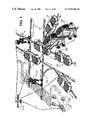
- FIG. 1 is a perspective plain view of a street crossing with self operating E-POOL traffic, transport and distribution group arrangements, and of position and direction code train guide-ways, as also of the E-POOL network-data exchange;
- FIGS. 2A , 2 B, 2 C is the sectional side view of a contact protected under floor current and communication supply line with entrance-exit pivoting units, in the moment of exit pivoting movement, of the current and communication commutator carriage of an E-POOL individual car, the front and rear view of two E-POOL vans and, to the drive direction laterally positioned, a contact protected under floor current and communication supply line with energy supply by means of multiblock-solar-wind power stations; the front view of an E-POOL van with sectional view through a contact protected under floor current and communication supply line and of the energy supply by means of laterally to the drive direction positioned mutliblock-solar-wind power stations;
- FIGS. 3A , 3 B is the perspective view of an E-POOL vehicle chassis with engagement of the current and communication commutator carriage to a contact protected under floor current and communication supply line; the detail of the position and direction code train guide-way;
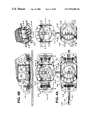
- FIGS. 4A , 4 B is the plain view of an E-POOL individual car and the motion cycle for the change of drive to the lateral direction, with the detail of a pivoting inside compartment; the side view with a perspective detail of a pivoting inside compartment
- FIG. 5 is the plain view of an E-POOL individual car and the motion cycle for the change of drive to the lateral direction, for a parking operation;
- FIGS. 6A , 6 B is the perspective plain view of two E-STOPS with an individual car and a van, and the train guide by means of a direction code train guide-way; the detail of a position and direction code train guide-way;
- FIG. 7 is the plain view of a multi-track expressway, on the middle strip with CO2 free E-POOL energy supply and on the both sided roads, the train guide by means of a position and direction code train guide-way of contact protected under floor current and communication supply lines, as also of contact protected upper road and street current and communication supply lines;
- FIGS. 8A , 8 B, 8 C is the front view of a middle strip sector of the expressway in accordance with FIG. 7 , with two rail-road-street transporters; the detail of the rail-road-street and street wheel units;
- FIGS. 9A , 9 B is the front view of an E-POOL rail-road-street transporter in accordance with the FIG. 8 , on a rail body with open overhead current and communication supply line; the detail of a rail-road-street and street wheel unit on the rail body;
- FIGS. 10A , 10 B is the side view of an E-POOL rail-road-street transporter and data exchange with the E-POOL satellite units; a rail-road respectively street driving up detail;
- FIGS. 11A , B is the plain and sectional view of train guide-way leaded traffic and distribution group arrangements; available E-POOL traffic and distribution group arrangements in an availability subway, at the roads side strip;
- FIGS. 12A , B is the side view of a distribution group arrangement, coupling with a multiblock robot service vehicle and preparation of a stationary refrigerator and distribution box, as also the data exchange with the E-POOL central computers and the E-POOL satellite units; the perspective view of a multiblock transport robot, transporting a stationary refrigerator and distribution box;
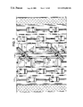
- FIGS. 13A , B, C, D is the perspective view of an E-POOL multiblock transport robot with a floor and overhead train guide way, transporting a stationary refrigerator and distribution box; the detail of a robot arm with hydraulic socket flange booster chamber; the central train guide way channel of tie multiblock standard parts in a longitudinal, sectional view; the corresponding plain view;
- FIGS. 14A , B is the side view of a mobile production and composition group arrangement in accordance with the FIG. 12 , preparing mobile, train guide-way leaded refrigerator and distribution boxes; the corresponding plain view;
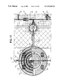
- FIG. 15 is the semi-sectional front view of a large scale distribution group arrangement with pivoted current and communication carriage within a contact protected under floor current and communication supply line;
- FIG. 16 is the perspective view of two train guide way leaded E-POOL delivery-distribution assembly group arrangements and a direct withdrawal-distribution group arrangement, as also a train guide way leaded multiblock road and street operation robot;
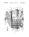
- FIG. 17 is the semi-sectional plain view of a train guide way leaded production and composition group arrangement, carrying out a freight unload by means of a telescop carrier, as also a sectional view of a house entrance with elevator, and floor load transport by means of an E-POOL multiblock house service robot;
- FIG. 18 is the perspective view of a stationary E-POOL production and composition group arrangement, for the production and delivery of goods, with the clearance of an E-POOL transport vehicle, as also of an E-POOL multiblock security robot on a circular train guide way around the systems cell unit, and the data exchange with E-POOL satellite units;
- FIG. 19 is the perspective view of a stationary double floor E-POOL production and composition group arrangement for the production and delivery of goods, with the clearance of an E-POOL transport vehicle, the arrival of mobile production and composition group arrangements and of a multiblock transport robot, as also the data exchange with E-POOL central computers by means of the E-POOL satellite units;
- FIG. 20 is the perspective view of a stationary serial E-POOL production and composition group arrangement, composed of three stationary production and composition group arrangements in accordance with the FIG. 18 , for the production and composition of goods, with connection to train guide way leaded E-POOL transport group arrangements and the arrival of small distribution group arrangements and of a multiblock transport robot.
- Movement arrows in the FIGS. show the movement direction of the system parts
- signal arrows show the direction of the data exchange
- view arrows show the origin and the line of vision for system details, sub-views and sections of the respective FIGS.
- Multiblock robot prodcution and distribution networks in accordance with FIGS. 1 and 2 are self operating.
- This means for the present invention that after the users input of order commands via the E-POOL order software and the individual E-POOL computer units 3 - 16 with data exchange over the electronic E-POOL network, for precise deliveries, compositions and services, E-POOL transaction process chains are running collision free, with operational reliability, without any need for manual interferences, corrections, or operator supervisions, this also for leading back operations to the original availability positions, of the individual needed system group arrangements, after order accomplishment.
- E-POOL system group arrangements are always reinstructable by means of new commands and order inputs, over users E-POOL computer terminals 3 - 16 , and localy, directly at the system group arrangements, by means of speech reproduction codes and E-POOL user checkcards.
- the traffic, transport and distribution system group arrangements are leaded on position and direction code train guide-ways 3 - 5 .
- the notebook E-POOL multiblock robots of an E-POOL compound are identical in its structure and construction. However they differ from each other by the different socket flange booster chambers 9 and 9 ′ which, like the hydraulic socket flange booster chambers 9 ′- 31 of the FIG.
- E-POOL multiblock road and street operation robots 1 - 2 , E-POOL individual cars 1 - 4 and E-POOL delivery-distribution group arrangements 1 - 10 are leaded on the position and direction code train guide-ways 3 - 5 , having continuously data exchange with the E-POOL satellite units 9 ′- 32 , for the precise positioned order execution.
- Contact protected under floor and upper floor current and communication supply lines 3 - 11 , 3 - 12 allow the needed power supply and the high-performance movements of the traffic, transport and distribution group arrangements, whereas the battery energy reserves remain saved.
- the traffic, transport and distribution group arrangements shown as individual cars and vans, are provided with under floor and upper floor current and communication pivoting arms 3 - 13 , 3 - 14 , with accessory current and communication commutator carriage 3 - 4 for the current connection from the under floor and upper floor current and communication supply lines 3 - 11 , 3 - 12 to the drive units of the traffic, transport and distribution group arrangements.
- the current conductors of the under floor and upper floor current and communication supply lines 3 - 11 , 3 - 12 are clamped at insulators 3 - 19 and so secured leaded.
- entrance-exit pivoting units 3 - 15 which permit the swing in and out of the under floor and upper floor current and communication pivoting arms 3 - 13 , 3 - 14 , to and from the under floor and upper floor current and communication supply lines 3 - 11 , 3 - 12 , without a drive interruption.
- the upper floor current and communication supply lines 3 - 12 are equal in its structure to the under floor current and communication supply lines 3 - 11 , with integration of entrance-exit pivoting units 3 - 15 , however, in relation to the under floor current and communication supply lines 3 - 11 , they are arranged, displaced at 90° or 180°, in relation to the under floor current and communication supply lines 3 - 11 , with a corresponding horizontal displacement at 90° of the upper floor current and communication pivoting arms 3 - 14 appertaining to the traffic, transport and distribution group arrangements and a corresponding displacement at 90° and 180° of the current and communication commutator carriage 3 - 4 , which are engaged in the upper floor current and communication supply lines 3 - 12 .
- the contact protected under floor current and communication supply lines 3 - 11 are provided with water discharge slots, positioned in distances to each other, for the discharge of rain water, to water discharge channels 9 ′- 24 , leaded directly below the under floor current and communication supply lines 3 - 11 , these provided with sewage pumps 9 ′- 33 in greater distances to each other and discharging the sewage water into the public terminal.
- E-STOP multiblock solar and wind power stations 1 - 21 installed in center line position to the drive directions, but also laterally at the road and street sides, connected with the contact protected under floor current and communication supply lines 3 - 11 , by means of socket flange booster chambers 9 ′- 19 .
- the contact protected under floor and upper floor current and communication supply lines 3 - 11 having position and direction code train guide-ways 3 - 5 , which are provided in thin-coat varnish and thin layer metalised adhesive foils, to the left and to the right of the engagement slot for the under floor current and communication pivoting arms 3 - 14 , and which are exactly identical to the position and direction code train guide-ways 3 - 5 , deposited on the road and street surfaces, in accordance with FIG. 1 .
- the under floor current and communication supply lines 3 - 11 can be installed, at any places, in anly length, straight lined or curved, for position and direction code train guide-ways 3 - 5 marked roads and streets, without that, at the final swing in, swing out position of the there positioned entrance-exit pivoting units 3 - 15 , are arising orientation problems for the pivoting-arms sensors 9 ′- 20 , which are scanning contactless the direction course of the position and direction code train guide-ways 3 - 5 , and are transmitting the control signals to the board computers 9 ′- 1 or the corresponding steering adjustment of the multiblock robot drive units 9 - 9 , 9 - 23 , 9 - 29 .
- the direction code train guide-ways 3 - 5 having moreover, to the left and to the right of the there remaining free, center lined strip unit, in the width of the engagement slot for the under floor current and communication pivoting arms 3 - 14 , always centrally, a longitudinal, continuously traversing additional metalised thin-coat varnish, the inductive strip 3 - 8 , which marks the drive direction and which is contactless scanned by the pivoting-arms sensors 9 ′- 20 .
- To the left and to the right of the inductive strip 3 - 8 in distances to each other, are additionally position identification marks 3 - 9 varnished, or in thin layer metalised adhesive foils deposited on the direction code train guide-ways 3 - 5 .
- the position identification marks 3 - 9 mark the position points along the position and direction code train guide-ways 3 - 5 and are likewise contactless scanned from the pivoting-arms sensors 9 ′- 20 , and the position signals are transmitted to the board computers 9 ′- 1 for the continuous comparison of rated and actual positions.
- control point identification marks 3 - 10 are varnished and deposited in thin layer metalised adhesive foils, which, in the moment of reaching and scanning from the pivoting-arms sensors 9 ′- 20 , are transmitting control informations to the board computers 9 ′- 1 and to the central computers 3 - 17 , especially if reaching the position marks of the entrance-exit pivoting units 3 - 15 and for the self operating swing in and swing out of these units, in the case that the under floor current and communication pivoting arms 3 - 14 have to be pivoted to or from the under floor current and communication supply lines 3 - 11 .
- the metalised thin-coat varnish and the thin layer metalised adhesive foils with the inductive strips 3 - 8 , the position identification marks 3 - 9 and the control point identification marks 3 - 10 have inductive properties, so that they can be scanned contactless by the pivoting-arms sensors 9 ′- 20 without signal information losts, even in the case of soiling.
- thin layer metalised adhesive foils, with identical properties as provided for the varnished metalised thin-coats, are glued on the roads.
- the water discharge channels 9 ′- 24 leaded directly below the contact protected under floor current and communication supply lines 3 - 11 , have a conical structure in bottom direction and show the water discharge fitting with the multiblock-water discharge pump 9 ′- 33 and the discharge into the public exchange.
- the under floor current and communication pivoting arms 3 - 14 are plug connected, exactly in central back position on rotation flange plug connections 2 - 2 of the chassis frame 9 ′- 8 , which is equiped with the multiblock drive units 9 ′- 9 , 9 ′- 23 , the wheel sensors 9 ′- 10 , the chassis sensors 9 ′- 21 and to these belonging rotation flange plug connections 2 - 2 , so that the chassis frames 9 ′- 8 are always centrally positioned to the direction code train guide-ways 3 - 5 .
- the E-POOL traffic, transport and distribution system group arrangements receive pivoting inside compartments 9 ′- 28 , instead of the usually used doors. These are pluged on central multiblock robot standard parts 2 - 1 , which ensure the rotational drive, pivoting the inside compartments 9 ′- 28 freely to the left and to the right, at 360°, whereas the outside support during the pivoting movements, is accomplished by the annular chassis tracks 9 ′- 38 , with its annular roller supported step bearings 9 ′- 39 .
- the pivoting inside compartments 9 ′- 28 are provided with an automobile body cover structure 9 ′- 37 with side-window insertion.
- the automobile body cover structure 9 ′- 37 is in general adapted to the respective automobile body of the E-POOL traffic, transport and distribution system group arrangements. They are sealed off at the transition to the automobile body front and rear side, by means of longitudinal roller sealing rubbers 9 ′- 28 ′, closing the automobile body cover structure 9 ′- 37 tightly to the outside, during the swing-in state, ready for drive.
- the inside walls of the automobile body cover structure 9 ′- 37 have to the left and to the right, beside the seats, manually commanded control units 9 ′- 2 ′which comprise steering control units, for the manual steering take over of the users at every time, thus disconnecting the self operating functions.
- E-POOL checkcard reader unit 9 ′- 2 for a second necessary control check of a user justification, apart from the first control check of a user justification, by means of the E-POOL checkcard reader units 9 ′- 2 which are inserted at the outer contour of the car bodies and which, in the event of a vehicles possession take over by the E-POOL users, verify the E-POOL users justification, switching free the respective vehicle for entrance operations, followed by the release of the swing-out process of the automobile body cover structures 9 ′- 37 , for the comfortable and unhindered entrance.
- the automobile body cover structures 9 ′- 37 receive for the traffic, transport of objects, loads, robots and persons, the corresponding interior equipment like pallets, load forks, load elevating devices, containers, conveyor belts, two or more seats for persons.
- the individual cars 1 - 4 have two seats for persons with free room to the back side, for the reception of objects.
- the position and direction code train guide-ways 3 - 5 with the position identification marks 3 - 9 and the control point identification marks 3 - 10 , are also applied to sidewalks, in 90° to the road and street tracks.
- the vehicle is being braked and from the standing position, the four drive units 9 ′- 9 with the wheel units are completely pivoted at 90°, so that the individual car 1 - 4 drives directly to the exact reception-deposition place, without any need of multiple drive up and drive back corrections.
- the automobile body cover structures 9 ′- 37 are being pivoted at 90°, so that the lateral access openings are free.
- the seat or load unit is sliding in front position by means of the slide-in, slide-out unit 9 ′- 37 ′, up to the range that an unhindered entrance-exit and take over of objects and loads is possible.
- the E-POOL user checkcard is being inserted into the outside checkcard reader 9 ′- 2 and the automobile body cover structures 9 ′- 37 is being pivoted at 90° for the entry of persons.
- the access and departure, as also the position operations of vehicles at E-STOPS for the battery exchange or for the battery recharge, is likewise carried through precisely, without any shunting movement requirements, by means of the position and direction code train guide-ways 3 - 5 , with the inductive strips 3 - 8 , the position identification marks 3 - 9 and the control point identification marks 3 - 10 .
- the traffic, transport and distribution system group arrangements, in this case an individual car 14 and a van 14 are equiped with sensor outside rings 9 ′- 15 having sonar and infrared sensors for locating of objects and persons.
- image recognition units 9 ′- 22 at the sidewalls in front and back position, so that by means of the sonar, infrared and image evaluation of the board computers 9 ′- 1 , the environment of the vehicle is being continuously analysed for finding mobile or stationary obstacles and if necessary, brake and slow down control commands are transmitted to the drive units 9 ′- 9 .
- the distance to objects, mobile obstacles, as also to vehicles in front of the own are constantly messured by means of the chassis sensor units 9 ′- 21 and the speed being correspondingly adapted by means of the board computers 9 ′- 1 .
- the annular chassis tracks 9 ′- 38 are exactly positioned in the center line of the vehicles, resting on the vehicles chassis 9 ′- 8 .
- the E-POOL traffic, transport and distribution system group arrangements are equiped with pivoting roof solar units 9 ′- 25 , which in stand position are continuously pivoted to the accurate vertical, energy optimal utilization direction, of the sun beams. At the departure, the roof solar units 9 ′- 25 are again self operating pivoted to the original position, plain to the level of the vehicles roof
- the center strip is being used for multiblock solar and wind power stations 1 - 21 , having along the tracks, open current and communication supply lines 3 - 20 and upper floor current and communication supply lines 3 - 12 , for overhead current support of the heavy load transporters and busses 1 - 5 and of the rail-road-street transporters and busses 1 - 6 , by means of the upper floor current and communication pivoting arms 3 - 14 .
- the different E-POOL traffic, transport and distribution system group arrangements can optionally enter and exit each of the road and street tracks and use in each road and street direction and in each track, the position and direction code train guide-ways and the current and communication supply lines 3 - 11 .
- each track is equiped with a contact protected under floor current and communication supply line 3 - 11 .
- the upper floor and under floor current and communication supply lines 3 - 11 and 3 - 12 are directly connected with the current and communication channels, of the centrally to the road or street tracks installed multiblock solar and wind power stations 1 - 21 .
- the rail-road-street transporters 1 - 6 are equiped with rail-road-street and street wheel units 9 ′- 23 , for which the rail wheel 9 ′- 34 is being arranged in accordance with the rail guidance and drive arrangement, whether the rail wheel 9 ′- 34 in axie direction, directly beside the road and street wheel 9 ′- 35 , or through interposition of a multiblock standard part 2 - 1 .
- the rail wheel 9 ′- 34 and the road and street wheel 9 ′- 35 can also be arranged separately, one behind the other and in accordance with the use, rail or road and street, the respective needed wheel is being pivoted in upper or in lower position, and in the same way as for the current and communication pivoting arms 3 - 14 , pivoted by means of multiblock standard parts 2 - 1 .
- the rail wheels 9 ′- 34 have contact with the rails and the road and street wheels 9 ′- 35 being pivoted to the upper position and in the case of road and street drive, if the road and street wheels get contact with the roads and streets, the rail wheels being pivoted to the uper position.
- FIG. 10 shows, that there the position identification marks 3 - 9 and the control point identification marks 3 - 10 are deposited on the sleepers of the rail body, and they are contactless scanned from the multiblock standard parts 2 - 1 sensors 9 ′- 20 , 9 ′- 21 , of the under floor and upper floor current and communication pivoting arms 3 - 13 , 3 - 14 .
- the current and communication supply is provided by means of the open overhead current and communication supply lines 3 - 20 , through the roof current and communication pivoting arm 9 ′- 18 .
- the roof current and communication pivoting arm 9 ′- 18 is pivoted out, and the vehicle being disconnected from the open overhead current and communication supply lines 3 - 20 , and the under floor and upper floor current and communication pivoting arms 9 - 16 , 3 - 13 , 3 - 14 with its current and communication commutator carriage 3 - 4 are pivoted into the under floor current and communication supply lines 3 - 11 .
- the entrance-exit pivoting unit 3 - 15 is pivoted to the close position, flush with the roads and streets lane.
- the rail-road-street transporters and busses 1 - 6 have always constantly data exchange with the entire E-POOL network by means of the E-POOL satellite units 9 ′- 32 with its rotation flange plug connections and antenna units 9 ′- 3 .
- all multiblock standard parts 2 - 1 , the rotation flange plug connections 2 - 2 , the socket flange booster chambers 9 ′ are identical in its structure to each other.
- the identical structure is maintained.
- the multiblock robots 1 - 1 , 1 - 2 , 1 - 3 can always leaf the position and direction code train guide-ways 3 - 5 .
- E-POOL justified users and passengers of the E-POOL individual cars 14 and of the other traffic, transport and distribution group arrangements, are self operating checked-out if leaving the position and direction code train guide-ways 3 - 5 , ore checked-in, if entering the train guide way compound. For check-in operations, the users are asked by multiblock robot speech reproduction units to input the E-POOL user codes and the target of the ride.
- the board computer 9 - 1 computes the probable duration of the ride and gives in a user dialog more answers, as for the fare and a description of the way for reaching the ordered targeted position. If the user approves the quotation and declaration of the board computer 9 - 1 for the ride, the autopilot drive is being accomplished self operating, without any manual interference of the user, up to the final position.
- E-POOL compatible private vehicles are justified at every time to use the self operating E-POOL compound, the position and direction code train guide-ways 3 - 5 and the contact protected under floor and upper floor current and communication supply lines 3 - 11 , 3 - 12 , if the users are in possession of the E-POOL user checkcard and by input of the user justification code to the respective board computer 9 - 1 , so they are able to switch over from manual steering to order control, means totally self operating, autopilot drive to the targeted position, without any need for the drivers intervention.
- E-POOL availabilty subways 1 - 9 are provided and installed laterally to the roads and streets.
- the E-POOL availability subways 1 - 9 are equiped with contact protected under floor current and communication supply lines 3 - 11 and with E-STOPS.
- the entrance and exit openings are horizontally dosed by roller doors which are driven by multiblock drive units 2 - 1 .
- the multiblock street operation robots 1 - 2 dean and remove drive obstacles, provide new installations of contact protected current and communication supply lines 3 - 11 , 3 - 12 and position and direction code train guide-ways 3 - 5 , executing these works on its own belt and wheel drive units 9 ′- 29 , 9 ′- 9 , but also by means of multiblock robot service vehicles 1 - 14 , driving ahead of position and direction code train guide way laying-containers 1 - 15 , which are coupled to the multiblock robot service vehicles 1 - 14 .
- the position and direction code train guide way laying-containers 1 - 15 contain varnish material for the varnished metalised thin-coats of the position and direction code train guide-ways 3 - 5 , as also thin layer metalised adhesive foils composed of roll material, and in speedy operation cycles of vamisch marking and roll material laying road and street machines, positioned and controlled by the street operation robots 1 - 2 , they mark and lay down the position and direction code train guide-ways 3 - 5 , precisely and in exact positions on the roads and streets with optional directions, curves and ascents,
- the E-POOL distribution group arrangement 1 - 8 of FIG. 12 takes care of the stationary refrigerator and distribution boxes 1 - 12 , transfering these to the inside room of the distribution group arrangements 1 - 12 , by means of the telescopic carrier 1 - 22 , for replenishment, preparation of ordered goods like food, and after this, retransfers the stationary refrigerator and distribution boxes 1 - 12 to the outside for setting down operations on availability rotation flange plug connections 2 - 2 .
- the stationary refrigerator and distribution boxes 1 - 12 have at the bottom, as also in the range of the roof, rotation flange plug connections 2 - 2 for availability depositions and take over operations.
- the telescopic carriers 1 - 22 are equally provided with congruent rotation flange plug connections 2 - 2 and are able to pick up, transfer and to deposit, two of the stationary cool and distribution boxes 1 - 12 , at the same time together.
- a multiblock transport robot 1 - 1 taking over the stationary refrigerator and distribution boxes 1 - 12 and transporting these, train guided to the ordered destination.
- a multiblock street operation robot 1 - 2 in a multiblock robot service vehicle 1 - 14 is coupling to the E-POOL distribution group 1 - 8 , in order to take over materials for the road and street services.
- the drive units are composed of multiblock belt drive units 9 ′- 29 .
- All basic unit assembly groups have continuously data exchange by means of the under floor current and communication supply lines 3 - 11 , the antenna units 9 ′- 3 , the E-POOL satellite units 9 ′- 32 , and with the E-POOL central computer units 3 - 17 .
- the multiblock transport robot 1 - 1 in accordance with FIG. 13 is transporting the stationary refrigerator and distribution box 1 - 12 within a house floor.
- the house floor has position and direction code train guide-ways 3 - 5 on the ground and also under the ceiling.
- the multiblock transport robot 1 - 1 receives pivoting-arms sensors 9 ′- 20 at both ankles and additionally in the range of the ceiling at the robot solar unit, which is combined with the there centrally provided image recognition unit 9 ′- 22 and the antenna unit 9 ′- 3 . Furthermore is this multiblock transport robot 1 - 1 equiped with hydraulic socket flange booster chambers 9 ′- 31 which are pluged on the rotation flange plug connections 2 - 2 of the multiblock robot standard parts 2 - 1 .
- the hydraulic socket flange booster chambers 9 ′- 31 contain hydraulics pumps and hydraulics fluids 3 - 23 , which through a separated multi fluid channel 3 - 2 , sheathing the current and communication channels 3 - 1 , 3 ′- 1 of the multiblock standard parts 2 - 1 with its current conducters 3 - 22 and the communication conductors 3 - 21 , and leads hydraulic fluid 3 - 23 to hydraulic valves of the gear units 9 ′- 7 and of the gripper units and increases the torque of the rotation flange plug connections 2 - 2 , for the purpose of a higher load holding capacity.
- the multi fluid channels 3 - 2 have additional control chambers 3 ′- 2 For the control and return flow of the hydraulic fluids 3 - 23 .
- the mobile E-POOL production and composition group arrangement 1 - 8 is taking over mobile refrigerator and distribution boxes 1 - 13 , which are driving on multiblock wheel drive units 9 ′- 9 .
- the mobile production and composition group arrangement 18 is equally equiped with wheel drive units 9 ′- 9 .
- All chassis units have the under floor current and communication pivoting arms 3 - 13 pivoted out, so that, with its current and communication commutator carriage 3 - 4 , they have access to the contact protected under floor current and communication supply lines 3 - 11 , and they have orientation guides for positioning by means of the position and direction code train guide-ways 3 - 5 , on the lane surface.
- All mobile E-POOL production and composition group arrangements 1 - 8 are equiped with pivoting segment solar units 9 ′- 26 , surrounding the mobile E-POOL production and composition group arrangements 1 - 8 , under an inclination angle, for optimization of the energy yield by means of a far-reaching vertical positioning to the sun irradiation.
- the pivoting segment solar units 9 ′- 26 are pivoted and adapted in horizontal direction in accordance with the direction of the sun beams, independently of the respective position of the production and composition group arrangements 1 - 8 . This optimization being self operating similarly as for the pivoting inside compartments 9 ′- 28 of the FIGS.
- annular chassis tracks 9 ′- 38 and annular roller supported step bearings 9 ′- 39 which however, are here provided in roof position.
- a service robot 1 - 3 provided, which composes the orders, with access to the concentric, pivotable annular body 1 - 16 and load access to the access passage 1 - 20 and to the there made available, mobile refrigerator and distribution box 1 - 13 .
- the mobile refrigerator and distribution boxes 1 - 13 which have been completely processed by and within the mobile production and distribution group arrangements 1 - 8 , are put in line one behind or beside of the other on refrigerator availability grounds, centered on entrance-exit pivoting units 3 - 15 of the contact protected under floor current and communication supply lines 3 - 11 , pivoting immediatly the under floor current and communication pivoting arms 1 - 13 with its current and communication commutator carriages 3 - 4 into the under floor current and communication supply lines 3 - 11 .
- the mobile refrigerator and distribution boxes 1 - 13 have at the bottom section air condition socket flange booster chambers 9 ′- 41 . These using in the same way like the hydraulic socket flange booster chambers 9 ′- 31 of the FIG.
- the mobile refrigerator and distribution boxes 1 - 13 are driven on the own wheel drive units 9 ′- 9 and are guided by means of the position and direction code train guide-ways 3 - 5 , to the individual ordered points and destinations.
- all production and composition group arrangements 1 - 8 included the refrigerator and distribution boxes 1 - 12 , 1 - 13 have a structure and mode of function in accordance with FIG. 15 , however in correspondance with the use and size, equiped with different multiblock standard parts 2 - 1 and socket flange booster chambers 9 , 9 ′.
- the concentric, pivotable annular bodies 1 - 16 as like as the sealed rings 1 - 17 are driving on multiblock wheel drive units 9 ′- 9 on the concentrical circular tracks, and they are guided similarly as the pivoting inside compartments 9 ′- 28 of the FIG. 4 to 6 , on annular chassis tracks 9 ′- 38 .
- the concentric, pivotable annular bodies 1 - 16 are equiped with air condition socket flange booster chambers 9 ′- 41 and have optionally food, materials, goods, tools and most different devices.
- the sealed rings 1 - 17 are sealing the concentric, pivotable annular bodies 1 - 16 against each other, so that the most different components, materials, semi-finished products and stocks can be keeped closely beside to each other, volume optimized and through the concentric displacement technique, speed optimized manufactured, produced, processed and composed.
- the entire outside upper part is separately pivotable arround the center and it has, as like as the bottom part, an access passage 1 - 20 .
- each of the pivotable annular bodies 1 - 16 is provided with an access passage 1 - 20 , respectively an access opening.
- the passage and access to the separate pivotable annular bodies 1 - 16 from the inside and the outside is possible, if the access passages 1 - 20 and access openings are pivoted in, constituing a lined up continuous passage.
- the concentric pivotable annular body 1 - 16 supports the multiblock drive units 9 ′- 9 with the telescopic carrier 1 - 22 for its concentrical rotation in the inside room.
- the telescopic carrier 1 - 22 is provided for the take over of loads, multiblock robots 1 - 1 , 1 - 2 , 1 - 3 , stationary refrigerator and distribution boxes 1 - 12 , for the transfer on the telescopic carrier 1 - 22 from the outside to the inside and vice versa, as also for the material movements and work assistance of the multiblock robots 1 - 1 , 1 - 2 , 1 - 3 in the inside room.
- the multiblock robots 1 - 1 , 1 - 2 , 1 - 3 are equiped with lateral rotation flange plug connections 2 - 2 having roller units of the size in correspondence to the size of the telescopic runway.
- All distribution, production and composition group arrangements 1 - 7 , 1 - 8 , 1 - 10 , 1 - 11 , 1 - 23 are equiped with circular roof solar units 9 - 25 which are pivoted and horizontally and vertically adapted to the respective level and direction of the sun irradiation, by means of the multiblock robot pivoting arms 9 ′- 14 .
- These circular solar units 9 ′- 25 being installed in addition to the pivotable segment solar units 9 ′- 26 , provided at the outside circumference.
- the integrated antenna unit 9 ′- 3 being pivotable individually and independently from the circular roof solar unit 9 ′- 25 , for the optimal data exchange with E-POOL satellite units 9 ′- 32 , by means of the multiblock robot pivotable arm 9 ′- 14 .
- At the roof section are furthermore provided, air condition exhaust slots 9 ′- 41 ′.
- the drive security equipments, drive units, current access, signal control and sensoric operations, as like as the general operation, access and passage equipments, are otherwise totally identical to the corresponding equipment of the E-POOL transport group arrangements.
- the mobile production and composition group arrangements 1 - 8 being the largest distribution group arrangements, as such taking over materials and goods for the own production and composition, for the delivery to stationary and mobile refrigerator and distribution boxes 1 - 12 , 1 - 13 and for the composition of goods and the transfer to delivery-distribution group arrangements 1 - 10 , in accordance with the FIG. 16 .
- the delivery-distribution group arrangements 1 - 10 are commuter-distribution group arrangements for the direct goods take over from the stationary production and composition group arrangements 1 - 7 and 1 - 23 , in accordance with the FIGS.
- the concentric pivotable annular body 1 - 16 of the mobile production and composition group arrangements 1 - 10 and of the direct withdrawal-distribution group arrangements 1 - 11 are provided with purchase containers 1 - 24 , shelf containers and partitions.
- the E-POOL user checkcards are put into the outside reader slots 9 ′- 2 .
- the concentric pivotable annular bodies 1 - 16 are pivoted to the direction of the access openings 1 - 20 .
- the reserved access sector of the orderer opens and the E-POOL user has access to his order, to his purchase container 1 - 24 and his ordered goods within the shelf partitions.
- the mobile production and composition group arrangement 1 - 8 in accordance with the FIG. 17 , tranfers larger good units by means of the telescopic carrier 1 - 22 , for the direct house delivery and leads the goods to the house elevator. From there, the goods are transfered to the floors and to the apartements, to offices and other ordered positions, by means of position and direction code train guide-way 3 - 5 guided multiblock house service robots 1 - 3 .
- the stationary production and composition group arrangements 1 - 7 in accordance with the FIG. 18 comprise three concentric pivotable annular bodies 1 - 16 .
- a direct withdrawal distribution group arrangement 1 - 11 is being driven into the inside room, through the access openings 1 - 20 , for the take over operation of goods.
- position and direction code train guide-ways 3 - 5 which lead from the outside roads and streets to the inside room, the self operating drive and access is ensured from north, south, west and east directions for transport operations of transport and distribution group arrangements, directly into and from the inside rooms.
- the access openings 1 - 20 of the concentric annular bodies 1 - 16 of the sealed rings 1 - 17 in accordance with FIG. 15 , and the pivotable outside wall, is being pivoted up to the center line of the respective position and direction code train guide-ways 3 - 5 .
- the shown heavy load transporter 1 - 5 with installed stationary refrigerator and distribution boxes 1 - 12 has taken over, new ordered goods from within the stationary production and composition group arrangement 1 - 7 , and train guided it is leaving the installation.
- An additional position and direction code train guide-way 3 - 5 arround the stationary production and composition group arrangement 1 - 7 is provided, for the train guidance of a multiblock street operation robot 1 - 2 , which supervises the position and direction code train guide-ways 3 - 5 from and to the stationary production and composition group arrangement 1 - 7 , services and deans all of the position and direction code train guide-ways 3 - 5 and which moreover, on the circular position and direction code train guide-way 3 - 5 , safeguards the outside sectors against unauthorized access and entry.
- the double floor stationary production and composition group arrangement 1 - 23 in accordance with the FIG. 19 , has in its ground floor a separate availability room for transport vehicles and distribution group arrangements, and in its upper floor a production and composition group arrangement 1 - 7 .
- All self operating process chains of the E-POOL traffic, transport and distribution group arrangements and of the composition group arrangements 1 - 23 , released from the individual E-POOL computers 3 - 16 and from to these compatible computer units, are carried through in a continuous data exchange and compound over the electronic E-POOL network, with its E-POOL central computers 3 - 17 , the E-POOL satellite units 9 ′- 32 , the antenna units 9 - 3 , the sensor socket flange booster chambers, the sensor outside rings 9 ′- 15 , the board computers 9 - 1 , as like as over the information conducters within the under and upper floor current and communication supply lines 3 - 11 , 3 - 12 .
- the three production and composition group arrangements 1 - 7 which in accordance with FIG.
- the position and direction code train guide-ways 3 - 5 at the opposite side however, are leading the delivery and distribution group arrangements 1 - 10 and the multiblock transport robot 1 - 1 , directly into the inside room of the production and composition arrangement groups 1 - 10 , for the self operating take over of goods and for corresponding transport operations.
Landscapes
- Engineering & Computer Science (AREA)
- Mechanical Engineering (AREA)
- Transportation (AREA)
- Power Engineering (AREA)
- Life Sciences & Earth Sciences (AREA)
- Sustainable Development (AREA)
- Sustainable Energy (AREA)
- Robotics (AREA)
- Manipulator (AREA)
Applications Claiming Priority (1)
| Application Number | Priority Date | Filing Date | Title |
|---|---|---|---|
| DE19820110A DE19820110A1 (de) | 1998-05-06 | 1998-05-06 | Multiblock-Robot-System |
Publications (1)
| Publication Number | Publication Date |
|---|---|
| US6934603B1 true US6934603B1 (en) | 2005-08-23 |
Family
ID=7866778
Family Applications (1)
| Application Number | Title | Priority Date | Filing Date |
|---|---|---|---|
| US09/298,204 Expired - Fee Related US6934603B1 (en) | 1998-05-06 | 1999-04-23 | Multiblock robot system |
Country Status (3)
| Country | Link |
|---|---|
| US (1) | US6934603B1 (fr) |
| EP (1) | EP0955132A2 (fr) |
| DE (1) | DE19820110A1 (fr) |
Cited By (25)
| Publication number | Priority date | Publication date | Assignee | Title |
|---|---|---|---|---|
| US20060095170A1 (en) * | 2004-11-03 | 2006-05-04 | Samsung Electronics Co., Ltd. | System and method for identifying objects in a space |
| US20060210388A1 (en) * | 2004-12-01 | 2006-09-21 | Robert Giaier | Method of manipulating and assembling automotive frame, chassis, and body |
| US20080042877A1 (en) * | 2004-12-14 | 2008-02-21 | Kennedy Roger H | Integrated Traffic Management System |
| US20080151908A1 (en) * | 2006-12-21 | 2008-06-26 | Industrial Technology Research Institute | Method for information transmission with backbone network and a position monitoring system for multiple robotic devices |
| US7788000B1 (en) | 2009-02-17 | 2010-08-31 | Davis Jr William D | Public highway system |
| US20100326314A1 (en) * | 2009-06-30 | 2010-12-30 | Kissel Waldemar F | Integrated Multimodal Transportation System and Associated Infrastructure |
| US20110082612A1 (en) * | 2008-11-07 | 2011-04-07 | Toyota Jidosha Kabushiki Kaisha | Power feeding system for vehicle, electrically powered vehicle and power feeding apparatus for vehicle |
| US20120226398A1 (en) * | 2011-03-02 | 2012-09-06 | Bombardier Transportation Gmbh | System and Method of Controlling Supply Voltage Polarity on a Vehicle |
| US20150091506A1 (en) * | 2013-09-30 | 2015-04-02 | Elwha Llc | Communication and control regarding electricity provider for wireless electric vehicle electrical energy transfer |
| US9073442B2 (en) | 2010-03-16 | 2015-07-07 | Toyota Jidosha Kabushiki Kaisha | Inductively charged vehicle with automatic positioning |
| US9096236B2 (en) | 2011-08-18 | 2015-08-04 | Wfk & Associates, Llc | Transitional mode high speed rail systems |
| US9096235B2 (en) | 2009-06-30 | 2015-08-04 | Wfk & Associates, Llc | Universal multimodal transportation system and associated infrastructure |
| US20150371205A1 (en) * | 2008-06-09 | 2015-12-24 | Guestlogix, Inc. | Systems and methods facilitating mobile retail environments |
| US9365104B2 (en) | 2010-04-21 | 2016-06-14 | Toyota Jidosha Kabushiki Kaisha | Parking assist device for vehicle and electrically powered vehicle including the same |
| US9412515B2 (en) | 2013-09-30 | 2016-08-09 | Elwha, Llc | Communication and control regarding wireless electric vehicle electrical energy transfer |
| US9452685B2 (en) | 2013-09-30 | 2016-09-27 | Elwha Llc | Dwelling related information center associated with communication and control system and method for wireless electric vehicle electrical energy transfer |
| US9536655B2 (en) | 2010-12-01 | 2017-01-03 | Toyota Jidosha Kabushiki Kaisha | Wireless power feeding apparatus, vehicle, and method of controlling wireless power feeding system |
| US20170232611A1 (en) * | 2016-01-14 | 2017-08-17 | Purdue Research Foundation | Educational systems comprising programmable controllers and methods of teaching therewith |
| US10093194B2 (en) | 2013-09-30 | 2018-10-09 | Elwha Llc | Communication and control system and method regarding electric vehicle for wireless electric vehicle electrical energy transfer |
| US10144616B2 (en) * | 2016-06-10 | 2018-12-04 | Otis Elevator Company | Cab for vertical travel with controllable orientation for non-vertical travel |
| US20190232796A1 (en) * | 2018-01-30 | 2019-08-01 | Robert Applegate | Autonomous networked transportation system and method |
| USD921061S1 (en) * | 2019-02-20 | 2021-06-01 | Lg Electronics Inc. | Movable refrigerator |
| USD936720S1 (en) * | 2019-02-20 | 2021-11-23 | Lg Electronics Inc. | Driving module for robots |
| WO2023193807A1 (fr) * | 2022-04-08 | 2023-10-12 | 时代电服科技有限公司 | Station d'échange de batterie |
| US20240157569A1 (en) * | 2021-03-19 | 2024-05-16 | Honda Motor Co., Ltd. | Robot |
Families Citing this family (4)
| Publication number | Priority date | Publication date | Assignee | Title |
|---|---|---|---|---|
| DE102009015164A1 (de) * | 2009-03-26 | 2010-10-07 | Bayerische Motoren Werke Aktiengesellschaft | Kraftfahrzeug |
| DE102009019135B4 (de) | 2009-04-29 | 2018-09-06 | Siemens Aktiengesellschaft | Fördersystem zum Transportieren von Gepäck oder dergl. Stückgut, insbesondere von Fluggepäck |
| AT512796B1 (de) * | 2012-03-26 | 2013-12-15 | Siemens Ag Oesterreich | Schienenfahrzeug mit Solarzelle |
| DE102014207033A1 (de) * | 2014-04-11 | 2015-10-15 | Siemens Aktiengesellschaft | Verfahren und System zur Bereitstellung von elektrischer Energie für ein Energienetz |
Citations (6)
| Publication number | Priority date | Publication date | Assignee | Title |
|---|---|---|---|---|
| US4232988A (en) * | 1975-05-03 | 1980-11-11 | Uwe Kochanneck | Article storage and retrieval system |
| US4252488A (en) * | 1975-05-03 | 1981-02-24 | Uwe Kochanneck | Storage retrieval system with pivoted holder frames |
| US5241875A (en) * | 1990-09-24 | 1993-09-07 | Uwe Kochanneck | Multiblock-robot |
| US5850762A (en) * | 1995-05-16 | 1998-12-22 | Kochanneck; Uwe | Multi-block robot |
| US5852353A (en) * | 1996-04-22 | 1998-12-22 | Uwe Kochanneck | Multiblock robot system |
| US6014597A (en) * | 1996-05-30 | 2000-01-11 | Uwe Kochanneck | Distributed electric vehicle battery exchange network |
-
1998
- 1998-05-06 DE DE19820110A patent/DE19820110A1/de not_active Withdrawn
-
1999
- 1999-04-23 US US09/298,204 patent/US6934603B1/en not_active Expired - Fee Related
- 1999-05-05 EP EP99108907A patent/EP0955132A2/fr not_active Withdrawn
Patent Citations (6)
| Publication number | Priority date | Publication date | Assignee | Title |
|---|---|---|---|---|
| US4232988A (en) * | 1975-05-03 | 1980-11-11 | Uwe Kochanneck | Article storage and retrieval system |
| US4252488A (en) * | 1975-05-03 | 1981-02-24 | Uwe Kochanneck | Storage retrieval system with pivoted holder frames |
| US5241875A (en) * | 1990-09-24 | 1993-09-07 | Uwe Kochanneck | Multiblock-robot |
| US5850762A (en) * | 1995-05-16 | 1998-12-22 | Kochanneck; Uwe | Multi-block robot |
| US5852353A (en) * | 1996-04-22 | 1998-12-22 | Uwe Kochanneck | Multiblock robot system |
| US6014597A (en) * | 1996-05-30 | 2000-01-11 | Uwe Kochanneck | Distributed electric vehicle battery exchange network |
Non-Patent Citations (2)
| Title |
|---|
| Behringer et al., Road And Relative Ego-State Recognition, IEEE., pp. 385-390, 1990. * |
| Parent et al., Automated Urban Vehicles: ,Towards A Dual Mode PRT (Personal Rapid Transit), IEEE., pp. 3129-3134, 1996. * |
Cited By (42)
| Publication number | Priority date | Publication date | Assignee | Title |
|---|---|---|---|---|
| US7539563B2 (en) * | 2004-11-03 | 2009-05-26 | Samsung Electronics Co., Ltd. | System and method for identifying objects in a space |
| US20060095170A1 (en) * | 2004-11-03 | 2006-05-04 | Samsung Electronics Co., Ltd. | System and method for identifying objects in a space |
| US20060210388A1 (en) * | 2004-12-01 | 2006-09-21 | Robert Giaier | Method of manipulating and assembling automotive frame, chassis, and body |
| US20080042877A1 (en) * | 2004-12-14 | 2008-02-21 | Kennedy Roger H | Integrated Traffic Management System |
| US20080151908A1 (en) * | 2006-12-21 | 2008-06-26 | Industrial Technology Research Institute | Method for information transmission with backbone network and a position monitoring system for multiple robotic devices |
| US20150371205A1 (en) * | 2008-06-09 | 2015-12-24 | Guestlogix, Inc. | Systems and methods facilitating mobile retail environments |
| US10037519B2 (en) * | 2008-06-09 | 2018-07-31 | Guestlogix Inc. | Systems and methods facilitating mobile retail environments |
| US20140324260A1 (en) * | 2008-11-07 | 2014-10-30 | Toyota Jidosha Kabushiki Kaisha | Power feeding system for vehicle, electrically powered vehicle and power feeding apparatus for vehicle |
| US9902271B2 (en) * | 2008-11-07 | 2018-02-27 | Toyota Jidosha Kabushiki Kaisha | Power feeding system for vehicle, electrically powered vehicle and power feeding apparatus for vehicle |
| US20110082612A1 (en) * | 2008-11-07 | 2011-04-07 | Toyota Jidosha Kabushiki Kaisha | Power feeding system for vehicle, electrically powered vehicle and power feeding apparatus for vehicle |
| US10618411B2 (en) | 2008-11-07 | 2020-04-14 | Toyota Jidosha Kabushiki Kaisha | Power feeding system for vehicle, electrically powered vehicle and power feeding apparatus for vehicle |
| US8798829B2 (en) * | 2008-11-07 | 2014-08-05 | Toyota Jidosha Kabushiki Kaisha | Power feeding system for vehicle, electrically powered vehicle and power feeding apparatus for vehicle |
| US7788000B1 (en) | 2009-02-17 | 2010-08-31 | Davis Jr William D | Public highway system |
| US8342101B2 (en) * | 2009-06-30 | 2013-01-01 | Wfk & Associates, Llc | Integrated multimodal transportation system and associated infrastructure |
| US9096235B2 (en) | 2009-06-30 | 2015-08-04 | Wfk & Associates, Llc | Universal multimodal transportation system and associated infrastructure |
| US20100326314A1 (en) * | 2009-06-30 | 2010-12-30 | Kissel Waldemar F | Integrated Multimodal Transportation System and Associated Infrastructure |
| US9073442B2 (en) | 2010-03-16 | 2015-07-07 | Toyota Jidosha Kabushiki Kaisha | Inductively charged vehicle with automatic positioning |
| US9981566B2 (en) | 2010-03-16 | 2018-05-29 | Toyota Jidosha Kabushiki Kaisha | Inductively charged vehicle with automatic positioning |
| US9365104B2 (en) | 2010-04-21 | 2016-06-14 | Toyota Jidosha Kabushiki Kaisha | Parking assist device for vehicle and electrically powered vehicle including the same |
| US9536655B2 (en) | 2010-12-01 | 2017-01-03 | Toyota Jidosha Kabushiki Kaisha | Wireless power feeding apparatus, vehicle, and method of controlling wireless power feeding system |
| US8386108B2 (en) * | 2011-03-02 | 2013-02-26 | Bombardier Transportation Gmbh | System and method of controlling supply voltage polarity on a vehicle |
| US20120226398A1 (en) * | 2011-03-02 | 2012-09-06 | Bombardier Transportation Gmbh | System and Method of Controlling Supply Voltage Polarity on a Vehicle |
| US9096236B2 (en) | 2011-08-18 | 2015-08-04 | Wfk & Associates, Llc | Transitional mode high speed rail systems |
| US9415783B2 (en) | 2011-08-18 | 2016-08-16 | Wfk & Associates, Llc | Transitional mode high speed rail systems |
| US9205754B2 (en) * | 2013-09-30 | 2015-12-08 | Elwha Llc | Communication and control regarding electricity provider for wireless electric vehicle electrical energy transfer |
| US9412515B2 (en) | 2013-09-30 | 2016-08-09 | Elwha, Llc | Communication and control regarding wireless electric vehicle electrical energy transfer |
| US9199549B2 (en) | 2013-09-30 | 2015-12-01 | Elwha Llc | Communication and control system and method regarding electric vehicle for wireless electric vehicle electrical energy transfer |
| US9457677B2 (en) | 2013-09-30 | 2016-10-04 | Elwha Llc | User interface to employment related information center associated with communication and control system and method for wireless electric vehicle electrical energy transfer |
| US10011180B2 (en) | 2013-09-30 | 2018-07-03 | Elwha, Llc | Communication and control system and method regarding electric vehicle charging equipment for wireless electric vehicle electrical energy transfer |
| US20150091506A1 (en) * | 2013-09-30 | 2015-04-02 | Elwha Llc | Communication and control regarding electricity provider for wireless electric vehicle electrical energy transfer |
| US10093194B2 (en) | 2013-09-30 | 2018-10-09 | Elwha Llc | Communication and control system and method regarding electric vehicle for wireless electric vehicle electrical energy transfer |
| US9463704B2 (en) | 2013-09-30 | 2016-10-11 | Elwha Llc | Employment related information center associated with communication and control system and method for wireless electric vehicle electrical energy |
| US9452685B2 (en) | 2013-09-30 | 2016-09-27 | Elwha Llc | Dwelling related information center associated with communication and control system and method for wireless electric vehicle electrical energy transfer |
| US10456910B2 (en) * | 2016-01-14 | 2019-10-29 | Purdue Research Foundation | Educational systems comprising programmable controllers and methods of teaching therewith |
| US20170232611A1 (en) * | 2016-01-14 | 2017-08-17 | Purdue Research Foundation | Educational systems comprising programmable controllers and methods of teaching therewith |
| US10144616B2 (en) * | 2016-06-10 | 2018-12-04 | Otis Elevator Company | Cab for vertical travel with controllable orientation for non-vertical travel |
| US20190232796A1 (en) * | 2018-01-30 | 2019-08-01 | Robert Applegate | Autonomous networked transportation system and method |
| USD921061S1 (en) * | 2019-02-20 | 2021-06-01 | Lg Electronics Inc. | Movable refrigerator |
| USD936720S1 (en) * | 2019-02-20 | 2021-11-23 | Lg Electronics Inc. | Driving module for robots |
| US20240157569A1 (en) * | 2021-03-19 | 2024-05-16 | Honda Motor Co., Ltd. | Robot |
| US12508714B2 (en) * | 2021-03-19 | 2025-12-30 | Honda Motor Co., Ltd. | Robot |
| WO2023193807A1 (fr) * | 2022-04-08 | 2023-10-12 | 时代电服科技有限公司 | Station d'échange de batterie |
Also Published As
| Publication number | Publication date |
|---|---|
| EP0955132A2 (fr) | 1999-11-10 |
| DE19820110A1 (de) | 1999-02-11 |
Similar Documents
| Publication | Publication Date | Title |
|---|---|---|
| US6934603B1 (en) | Multiblock robot system | |
| US3368496A (en) | Transportation system | |
| JP2662499B2 (ja) | 自動車の駐車装置 | |
| US8146506B2 (en) | Active rail transport system | |
| CA1293960C (fr) | Systeme de transport ferroviaire | |
| CN107644310B (zh) | 一种城市管式物流运输方法 | |
| RU2758921C1 (ru) | Поездная система с самоходным одиночным вагоном | |
| KR20220079663A (ko) | 통합 모빌리티 시스템 | |
| JP2008534388A (ja) | 人々または貨物の特に都市区域内における大量輸送の方法と、同方法を実施するための輸送インフラ | |
| EP2266080A1 (fr) | Système logistique écologique pour marchandises | |
| CN107480932B (zh) | 一种城际智能物流系统 | |
| CN110741407A (zh) | 交通系统及输送方法 | |
| CN112158499B (zh) | 一种分布式物流系统 | |
| GB2400359B (en) | Station design for personal rapid transport systems | |
| CN112141637B (zh) | 自驱动运输车及其装卸方法以及配送系统 | |
| WO2003006299A2 (fr) | Systeme de transport pour passagers et marchandises ou conteneurs | |
| CN109625661A (zh) | 货箱、货运列车、货物运输系统及货物运输方法 | |
| JPH08290789A (ja) | 資材供給上および費用の観点で最適化した、工業製品特に車両の連続組立用組立プラント | |
| EP4172093B1 (fr) | Système de transport | |
| CN107609714B (zh) | 一种用于管式物流系统的路径规划方法 | |
| CN114771670A (zh) | 一种无人机配送用快递接驳智能小车 | |
| CN100478536C (zh) | 用于导轨运输系统的平面终点站 | |
| RU2205761C1 (ru) | Модульная транспортная система и способ ее эксплуатации | |
| EP3853097A1 (fr) | Système de train autonome à voiture unique | |
| Corbin | AIRTRANS: Intra-Airport Transportation System |
Legal Events
| Date | Code | Title | Description |
|---|---|---|---|
| REMI | Maintenance fee reminder mailed | ||
| FPAY | Fee payment |
Year of fee payment: 4 |
|
| SULP | Surcharge for late payment | ||
| REMI | Maintenance fee reminder mailed | ||
| LAPS | Lapse for failure to pay maintenance fees | ||
| STCH | Information on status: patent discontinuation |
Free format text: PATENT EXPIRED DUE TO NONPAYMENT OF MAINTENANCE FEES UNDER 37 CFR 1.362 |
|
| FP | Lapsed due to failure to pay maintenance fee |
Effective date: 20130823 |