US6955351B2 - Paper feeding device and sheet carrying device - Google Patents
Paper feeding device and sheet carrying device Download PDFInfo
- Publication number
- US6955351B2 US6955351B2 US10/279,844 US27984402A US6955351B2 US 6955351 B2 US6955351 B2 US 6955351B2 US 27984402 A US27984402 A US 27984402A US 6955351 B2 US6955351 B2 US 6955351B2
- Authority
- US
- United States
- Prior art keywords
- sheet
- document
- filler
- detecting
- guide
- Prior art date
- Legal status (The legal status is an assumption and is not a legal conclusion. Google has not performed a legal analysis and makes no representation as to the accuracy of the status listed.)
- Expired - Fee Related, expires
Links
- 239000000945 filler Substances 0.000 claims abstract description 71
- 238000011144 upstream manufacturing Methods 0.000 claims abstract description 29
- 238000005452 bending Methods 0.000 claims description 22
- 210000000078 claw Anatomy 0.000 claims description 10
- 238000009434 installation Methods 0.000 claims description 9
- 229920002799 BoPET Polymers 0.000 abstract description 80
- 239000000463 material Substances 0.000 abstract description 8
- 238000000926 separation method Methods 0.000 description 29
- 239000000853 adhesive Substances 0.000 description 8
- 230000001070 adhesive effect Effects 0.000 description 8
- 238000007599 discharging Methods 0.000 description 6
- 239000011521 glass Substances 0.000 description 5
- 239000005020 polyethylene terephthalate Substances 0.000 description 3
- 229920000139 polyethylene terephthalate Polymers 0.000 description 3
- 238000011084 recovery Methods 0.000 description 3
- 230000008901 benefit Effects 0.000 description 2
- 238000003780 insertion Methods 0.000 description 2
- 230000037431 insertion Effects 0.000 description 2
- 238000012986 modification Methods 0.000 description 2
- 230000004048 modification Effects 0.000 description 2
- 238000007796 conventional method Methods 0.000 description 1
- 238000010586 diagram Methods 0.000 description 1
- 230000000694 effects Effects 0.000 description 1
- 230000005489 elastic deformation Effects 0.000 description 1
- 238000012840 feeding operation Methods 0.000 description 1
- 238000004519 manufacturing process Methods 0.000 description 1
- 238000000034 method Methods 0.000 description 1
- 239000004033 plastic Substances 0.000 description 1
Images


Classifications
-
- B—PERFORMING OPERATIONS; TRANSPORTING
- B65—CONVEYING; PACKING; STORING; HANDLING THIN OR FILAMENTARY MATERIAL
- B65H—HANDLING THIN OR FILAMENTARY MATERIAL, e.g. SHEETS, WEBS, CABLES
- B65H7/00—Controlling article feeding, separating, pile-advancing, or associated apparatus, to take account of incorrect feeding, absence of articles, or presence of faulty articles
- B65H7/02—Controlling article feeding, separating, pile-advancing, or associated apparatus, to take account of incorrect feeding, absence of articles, or presence of faulty articles by feelers or detectors
- B65H7/06—Controlling article feeding, separating, pile-advancing, or associated apparatus, to take account of incorrect feeding, absence of articles, or presence of faulty articles by feelers or detectors responsive to presence of faulty articles or incorrect separation or feed
- B65H7/08—Controlling article feeding, separating, pile-advancing, or associated apparatus, to take account of incorrect feeding, absence of articles, or presence of faulty articles by feelers or detectors responsive to presence of faulty articles or incorrect separation or feed responsive to incorrect front register
-
- B—PERFORMING OPERATIONS; TRANSPORTING
- B65—CONVEYING; PACKING; STORING; HANDLING THIN OR FILAMENTARY MATERIAL
- B65H—HANDLING THIN OR FILAMENTARY MATERIAL, e.g. SHEETS, WEBS, CABLES
- B65H9/00—Registering, e.g. orientating, articles; Devices therefor
- B65H9/06—Movable stops or gauges, e.g. rising and falling front stops
-
- B—PERFORMING OPERATIONS; TRANSPORTING
- B65—CONVEYING; PACKING; STORING; HANDLING THIN OR FILAMENTARY MATERIAL
- B65H—HANDLING THIN OR FILAMENTARY MATERIAL, e.g. SHEETS, WEBS, CABLES
- B65H2511/00—Dimensions; Position; Numbers; Identification; Occurrences
- B65H2511/20—Location in space
- B65H2511/21—Angle
- B65H2511/212—Rotary position
-
- B—PERFORMING OPERATIONS; TRANSPORTING
- B65—CONVEYING; PACKING; STORING; HANDLING THIN OR FILAMENTARY MATERIAL
- B65H—HANDLING THIN OR FILAMENTARY MATERIAL, e.g. SHEETS, WEBS, CABLES
- B65H2511/00—Dimensions; Position; Numbers; Identification; Occurrences
- B65H2511/50—Occurence
- B65H2511/51—Presence
-
- B—PERFORMING OPERATIONS; TRANSPORTING
- B65—CONVEYING; PACKING; STORING; HANDLING THIN OR FILAMENTARY MATERIAL
- B65H—HANDLING THIN OR FILAMENTARY MATERIAL, e.g. SHEETS, WEBS, CABLES
- B65H2553/00—Sensing or detecting means
- B65H2553/60—Details of intermediate means between the sensing means and the element to be sensed
- B65H2553/61—Mechanical means, e.g. contact arms
Definitions
- This invention relates in general to a paper feeding device and a sheet carrying device wherein the sheet loaded on a carrier plate can be detected and the sheet can be fed towards a predetermined position.
- a conventional paper feeding device comprises a paper-feeding roller, a paper-detecting member and a plate-shaped paper guide.
- the paper-feeding roller feeds a sheet through a tray loaded with sheets such as documents to be read or stationery etc.
- the paper-detecting member is arranged at an upstream side in a carrying direction of the paper-feeding roller.
- the plate-shaped paper guide is set between the paper-detecting member and the paper-feeding roller. Only a small gap exists between the paper guide and the sheet loaded on the tray (Japan Laid-open Publication no. He7-330182).
- a mechanical type (a filler type) document-detecting sensor is set in a document set portion.
- the length of the filler depends on the size of the paper-feeding path (the gap which the paper passes through). If the paper-feeding path is large, the filler has to be longer, while if the paper-feeding path is small, the filler has to be shorter. That is because the filler crosses (overlaps) an upper guide plate and a lower guide plate.
- the paper feed path must be set to be wide enough.
- FIG. 9A if there is a gap between the filler of the document-detecting sensor 2 and the upper guide plate 11 , if the total height of loaded document 13 is increased, the upmost document 13 may not be detected by the document-detecting sensor 2 .
- FIG. 9B if the gap between the filler of the document-detecting sensor 2 and the upper guide plate 11 is small, as the upper guide plate 11 is lowered down, the number of sheets of the document 13 for loading must be reduced.
- a sheet-shaped paper guide (MYLAR®) 14 a is set at the upstream side in the paper-feeding direction of the filler of the document-detecting sensor 2 .
- the MYLAR® 14 a actuates the document 13 towards the detecting side of the filler of the document-detecting sensor 2 according to the number of sheets of the document 13 .
- the thin document 13 carried through the gap still cannot be detected by the document-detecting sensor 2 . This may delay the thin document 13 from moving to the side of the feeding roller. Moreover, under this condition, the front end of the document 13 will move up and down due to the vibration when the device is driven. The operation for detecting the document 13 is not stable. Additionally, in the structure for holding a pick up roller through a magnetic clutch, one sheet of document 13 is picked up to feed and the magnetic clutch is switched off when the rear end of the document 13 is pulled by the pick up roller.
- the front end of the document 13 to be picked up is free to move up and down.
- the second document 13 is pushed back by the operation of a one-way clutch.
- the document 13 will be pushed back so much that the detecting operation of the document-detecting sensor 2 is not stable.
- the front end of the sheet-shaped MYLAR® 14 a bends backward to the upstream side in the carrying direction. This situation may obstruct the setting of thin paper or the setting of a fewer-sheet document 13 .
- the present invention provides a paper feeding device and a sheet carrying device that can detect if the sheet is set in a predetermined position no matter what the thickness of the paper or the number of sheets of the document is.
- a paper feeding device comprising: a carrier plate for loading a sheet, a detecting means for detecting the sheet loaded on the carrier plate, and a guide means made of a sheet-shaped resilience member A part of the guide means is in contact with a sheet carrying surface at an upstream side of a detecting position of the detecting means, and the guide means guides the sheet towards the detecting position during the guides means pushing an upper surface of the sheet.
- the sheet-shaped resilience member is bent into a loop shape, and the sheet carrying surface is in contact with a part of the loop shape.
- the sheet such as a document is guided to the filler of the document-detecting sensor such that a part of the loop of the MYLAR® is in contact with the document, the document can be smoothly guided with respect to the document-detecting sensor, and then the shape of the MYLAR® can be stable. Moreover, because the portion in contact with the document is formed in a smooth curve (loop (gradual circular) shape), the setting of the document etc. can be prevented from buckling. Furthermore, due to the resilience of the MYLAR®, even if the contacting position where the loop shape of the MYLAR® is in contact with the carrying surface moves during opening or closing the upper guide plate, or during pulling the document, the position can quickly return to the original contacting position by inserting the next document.
- the MYLAR® when the guide shape of the MYLAR® imitates the adhesive surface to be in contact with the carrying surface, the MYLAR® is not evenly pushed due the curve of MYLAR®.
- the front end of the MYLAR® bends backward towards the upstream side in the paper-feeding direction, and then the document can be set.
- the detecting means comprise a filler protruding from the sheet carrying surface when the sheet is not detected and retroceding after the filler touches the sheet loaded in the carrier plate.
- the filler and the guide means overlap each other when the sheet is not detected and a long hole is set in the loop shape of the guide means.
- the loop of the MYLAR® constructing the guide means is formed into a two-way shape for example.
- the filler of the document-detecting sensor can be arranged between the two-way shape without touching the loop. Therefore, the MYLAR® and the filler can be prevented from interference, and then the limitation of the layout can be eased to make the device slimmer.
- bending claws are set at an end in a longitudinal direction of the guide means to install the guide means onto an upper guide plate oppositely set at an upper side of the sheet carrying surface.
- an installation position of the guide means is at an upstream side in a feed direction of a position such that the guide means is in contact with the sheet carrying surface.
- the front end of the loop of the MYLAR® moves towards the upstream side in the paper-feeding direction during opening or closing of the upper guide plate (serving as a cover)
- the front end of the loop can be quickly changed to move towards the downstream side in the paper-feeding direction by inserting the next document and due to the loop shape and the flexibility of the MYLAR®.
- a sheet carrying device comprising the paper feeding device described as above.
- the sheet such as a document which is set at a feeding start position, can be detected no matter what the thickness of the paper or the number of the sheets of the document is, and then the sheet carrying device with a stable feeding operation can be achieved.
- FIG. 1 briefly shows the structure of the image-reading device related to the first embodiment of the present invention
- FIG. 2 shows a roller portion of an automatic document-feeding device related to the first embodiment of the present invention
- FIG. 3 is a perspective view showing main parts of a paper feeding device related to the first embodiment of the present invention
- FIG. 4 is a cross-sectional view showing a paper feeding device related to the first embodiment of the present invention.
- FIGS. 5A , 5 B show structures of a MYLAR® related to the first embodiment of the present invention
- FIG. 6 is a cross-sectional view showing main parts of a paper feeding device related to the second embodiment of the present invention.
- FIGS. 7A , 7 B show structures of a MYLAR® related to the second embodiment of the present invention
- FIGS. 8A , 8 B show the operation of the conventional document-detecting sensor (with one sheet of document);
- FIGS. 9A , 9 B show the operation of the conventional document-detecting sensor (with stacking sheets of document).
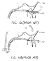
- FIGS. 10A , 10 B show the operation of the conventional document-detecting sensor with a document guide set therein.
- a sheet carrying device 50 comprises a paper feeding device.
- the paper feeding device (as shown in FIGS. 3 and 4 ) comprises a document tray 5 for loading a document 13 , a document-detecting sensor 2 for detecting the sheet loaded on the document tray 5 and a document guide (MYLAR®) 15 .
- the document guide 15 is made of a sheet-shaped resilience member (the member using PET etc). A part of the document guide 15 is in contact with a document carrying surface in a paper-feeding direction of a detecting position of the document-detecting sensor 2 , and the document guide 15 guides the document 13 towards the detecting position when the document guide 15 pushes the upper surface of the document 13 .
- the automatic document-feeding device (ADF, hereinafter) 50 is carried onto the upper portion of the body of the image reading device 60 .
- a reading portion is set on the lower portion of the contact glass 6 of the image reading device 60 for reading the image surface of the sheet-shaped document 13 .
- the exposure lamp 132 and the first mirror 131 moves left and right in FIG. 1 at the lower side of the contact glass 6 so that the reading portion can read the document 13 (pressure plate mode).
- the exposure lamp 132 and the first mirror 131 are stopped under the contact glass 6 to read at a reading position (exposure position). It is known that the reflection of the light of the exposure lamp 132 reflected by the document surface is incident to the reading elements 121 , such as CCD etc., to form an image thereon by the first mirror 131 or a lens 133 .
- a separation feeding portion (the paper feeding device) is set in the ADF 50 , wherein the separation feeding portion comprises the document tray 5 for loading a document 13 , a pick up roller 3 for taking the upmost document 13 loaded on the document tray 5 , and a feed roller 1 and a separation roller 9 for constructing a separation mechanism etc.
- the front end in the paper-feeding direction of the document 13 loaded at a predetermined position on the document tray 5 is detected by the filler type document-detecting sensor 2 .
- the document guide (MYLAR®) 15 is set at the upstream side in the paper-feeding direction of the detecting position of the filler of the document-detecting sensor 2 for pushing the document 13 according to its number of sheets.
- the MYLAR® 15 guides the document 13 inserted into the gap between the upper guide plate 11 , which serves as a cover capable of opening and closing, and the lower guide plate 12 to the filler of the document-detecting sensor 2 . Furthermore, it is preferred that the location of the document-detecting sensor 2 is within the minimum size in the width direction of the document 13 and is close to the carrying center. Moreover, it is preferred that the location of the document-detecting sensor 2 is between the downstream side in the paper-feeding direction of the pick up position and the upstream side in the paper-feeding direction of the feed roller 1 .
- a carrying portion comprising a first reading roller 10 and a second reading roller 8 etc. is set in ADF 50 .
- the first reading roller 10 pulls the document 13 out of the separation mechanism and carries the document 13 to a resist position.
- the second reading roller 8 waits for the document 13 at a predetermined position at the upstream side of the reading position in the carrying direction. In a predetermined timing, the document 13 is carried to the reading position.
- a discharging portion which comprises a discharging roller 4 etc. for discharging the read document 13 towards the discharging tray is set in the ADF 50 .
- the structure of the roller portion of the ADF 50 is as shown in FIG. 2 .
- the feed roller 1 , the pick up roller 3 and separation roller 9 integrally form a separation feeding unit.
- the separation feeding unit is rotatably supported and rotates following the opening or closing of the upper guide plate 11 that serves as a cover.
- the pick up roller 3 is connected to the feed roller 1 through a timing belt.
- the driving of the feeding motor generated from the driving shaft of the feed roller 1 is transferred through the magnetic clutch.
- the separation roller 9 is rotatably supported onto a central shaft (the driving shaft).
- the separation roller 9 is driven by a friction through a torque limiter (not shown) having a predetermined torque.
- the separation roller 9 If the separation roller 9 is directly engaged with the feed roller 1 , or if the separation roller 9 is engaged with the feed roller 1 through one sheet of the document 13 , as the feed roller 1 rotates, the separation roller 9 rotates counterclockwise (CCW). Moreover, the separation roller 9 is set so that its rotation force is smaller than the torque of the torque limiter when two or more sheets of document 13 are between the feed roller 1 and the separation roller 9 . In this condition, the separation roller 9 rotates in the original driving direction as clockwise, so the redundant document 13 is pushed back to prevent double feed Additionally, the driving shaft of the separation roller 9 is connected to the motor shaft of the feed roller 1 through gears and the driving force of the separation roller 9 is obtained through the driving of the feed motor.
- the roller portion including the separation feeding unit is driven by the ADF controller (not shown).
- the ADF controller is input with detecting signals created by the document-detecting sensor 2 and other sensors (not shown), state signals created by motors (including the feed motor) for driving each roller etc., and control signals (feed starting signal etc.) output by the body of the image reading device 60 .
- the ADF controller outputs the detecting signals of the document-detecting sensor 2 etc. to the body of the image reading device 60 and the ADF controller controls to drive the feed motor, magnetic clutch and one-rotation clutch etc. according to the controller signals output by the body.
- the MYLAR® 15 is explained referring to FIGS. 3 and 4 .
- the MYLAR® 15 made of resilience material such as PET etc. is adhered onto a surface of a rib structure 21 formed on the upper portion of the upper guide plate 11 .
- the lower portion of the MYLAR® 15 is formed in a warp shape.
- the warp shape is further divided into two ways. Due to the two ways, the warp shape and the filler (the protrusion on the lower guide plate 12 protrudes towards the carry path) of the document-detecting sensor 2 overlap each other Furthermore, a part of the warp shape is in contact with the carrying surface of the lower guide plate 12 .
- the position that the loop shape of the MYLAR® 15 is in contact with the carrying surface is set at the upstream side in the paper-feeding direction of the detecting position of the filler of the document-detecting sensor 2 .
- the home position of the filler of the document-detecting sensor 2 is shown as a solid line and the detecting position is shown as a dotted line.
- the MYLAR® 15 has a small friction and reaction-force with respect to the document 13 . Due to the elastic deformation of the loop shape, the MYLAR® 15 can be prevented from damage resulting from contact with the parts of the feeding unit when open and close the upper guide plate 11 .
- FIGS. 5A , 5 B As shown in FIG. 5B , a strip window (long hole) is set on the MYLAR® 15 , and the MYLAR® 15 has bending portions (bending claws) 16 a , 16 b and adhesion locations (as shown as oblique portions at two ends in longitudinal direction in FIG. 5B ) for forming a loop shape There is an adhesive or a bonding-material on the bending portions 16 a , 16 b .
- the MYLAR® 15 is to be installed in the separation feeding portion of the ADF 50 , first, the two ends are adhered to each other to form a warp shape.
- the bending portions 16 a , 16 b are adhered onto the rib structure 21 of the upper guide plate 11
- the adhesive or the bonding-material can be replaced by two-face tape.
- the bending portions 16 a , 16 b are designed to be ear-shaped extending towards the longitudinal and vertical directions, the MYLAR® 15 can be restrained from detaching when the MYLAR® 15 is in contact with the inserted document 13 or rubbed due to open or close the upper guide plate 11 .
- the ADF 50 under the condition that the ADF 50 is lifted-down (automatic carrying mode), the first image surface of the document 13 is set facing-up in the document tray 5 . While the front end of the document 13 is being pushed, the front end of the document 13 is inserted in the gap between the lower guide plate 12 and the upper guide plate 11 At this time, the filler of the document-detecting sensor 2 rotates and detects the document 13 , and then the detecting information is transferred to the ADF controller (not shown).
- the start button (not shown) of the image-reading device 60 is pressed, the ADF controller receives the feeding signal to drive the feeding portion. As a result, each upmost document 13 is supplied onto the contact glass 6 of the reading portion one by one.
- the document 13 pushed due to the pick up roller 3 is taken from the upmost one by the pick up roller 3 , then one sheet of the document 13 will be separated and carried towards the separation mechanism comprising the feed roller 1 and the separation roller 9 .
- the separation roller 9 rotates clockwise to push back the redundant document 13
- the MYLAR® 15 pushes the upper surface of the next document 13 , and then the redundant document 13 is not pushed back too much Therefore, the detecting of the document-detecting sensor 2 is not led to be incorrect
- the pick up roller 3 is driven through a magnetic clutch.
- a resist sensor (not shown) detects the front end of the document 13 after it has been separated to match the timing that the front end of the document 13 passes through the reading portion of the body of the image reading device 60 and the timing for starting reading image. After a period of feeding the document 13 , if the front end of the document 13 does not reach the resist sensor, this state will be judged as a jam. As a result, after the image is read by the reading portion, the document 13 is carried and discharged to a discharging portion having a discharging roller 4 etc. Moreover, because the upper surface of the next document 13 is pushed by the MYLAR® 15 , the front end of the document 13 can be restricted to swing up and down due to the vibration during driving the device and the document-detecting operation can be restricted from being unstable
- the automatic document-feeding device 50 comprises the document tray 5 for loading the document 13 , the document-detecting sensor 2 for detecting the sheet loaded on a predetermined position in the document tray 5 and the sheet-shaped resilient member Because the automatic document-feeding device 50 further comprises the separation feeding portion in which the MYLAR® 15 is set such that a part of the MYLAR® 15 is in contact with the document carrying surface at the upstream side in the paper-feeding direction of the detecting position of the document-detecting sensor 2 and is set to guide the document 13 to the detecting position during pushing the upper surface of the document 13 , no matter how thick the paper is or what the number of sheets of the document is, it can be detected that the document 13 is set at the detecting position of the document-detecting sensor 2
- the automatic document-feeding device 50 comprises the separation paper-feeding portion, wherein a loop is bent to form in the MYLAR® and a part of the loop shape is in contact with the document carrying surface, and the filler of the document-detecting sensor 2 and the MYLAR® overlap each other when the document is not detected, the document 13 can be smoothly guided to the document-detecting sensor 2 and the MYLAR® 15 and the filler of the document-detecting sensor 2 can be prevented from being interfered. Therefore, the limitation for the layout can be eased to make the automatic document-feeding device 50 slimmer.
- FIG. 6 is a cross-sectional view showing main parts of the paper feeding device related to the second embodiment of the present invention. It is different from the first embodiment in that the MYLAR® 15 ′ of the paper feeding device set on the automatic document-feeding device (ADF) 50 is bent into a loop and the carrying surface of the document 13 is in contact with a part of the loop shape of the MYLAR® 15 ′, With the structure of the second embodiment, there is no need to set a long hole in the loop shape of the MYLAR® 15 ′, its manufacture is easy
- the paper feeding device in this embodiment is set in the ADF 50 of the first embodiment and this ADF 50 is carried on the body of the image reading device 60 as shown in the first embodiment.
- the whole structure is substantially the same as the first embodiment except the MYLAR® 15 ′.
- the same members as shown in FIG. 1 are with the same numerical references and the explanation thereof is omitted.
- the MYLAR® 15 ′ made of resilience material such as PET etc. is adhered onto the rib structure 21 formed on the upper portion of the upper guide plate 11 .
- the lower portion of the MYLAR® 15 ′ is formed into a warp shape.
- a part of the warp shape is in contact with the carrying surface of the lower guide plate 12 at the upstream side of the detecting position of the filler of the document-detecting sensor 2 , i.e. at the upstream side of the position such that the filler of the document-detecting sensor 2 protrudes towards the carrying surface of the lower guide plate 12 (as shown in the filler protrusion in right side in FIG. 6 ).
- the home position of the filler of the document-detecting sensor 2 is shown as a solid line and the detecting position is shown as a dotted line.
- the MYLAR® 15 ′ has bending portions (bending claws) 16 a ′, 16 b ′.
- the MYLAR® 15 ′ has bending portions (bending claws) 16 a ′, 16 b ′.
- the bending portions 16 a ′, 16 b ′ are bent to adhere onto the rib structure 21 of the upper guide plate 11 .
- the adhesive or the bonding material can be replaced by a two-face tape.
- the MYLAR® 15 ′ can be prevented from becoming detached due to the contact with the inserted document 13 or the friction resulting from opening or closing the upper guide plate 11 .
- the carrier plate is formed with the document tray 5 etc.
- the detecting means is formed with the document-detecting sensor 2 etc.
- the guide means is formed with the MYLAR® 15 , 15 ′ etc.
- the bending claws are formed with bending portions 16 a , 16 b , 16 a ′, 16 b′.
- the document guide is explained as a MYLAR® with a loop shape
- a pushing guide member made of plastic, or a rotatable roller can be used to achieve the same effects as the MYLAR®.
- the pushing guide member has the same cross-sectional shape as the MYLAR® 15 as shown in FIG. 4 and is formed into a two-way shape to overlap the filler of the document-detecting sensor 2 .
- the pushing guide member is rotatably supported onto the upper guide plate 11 by a supporting member such as a rotational shaft.
- a stopper is set to limit the rotation range of the pushing guide member.
- the position that the pushing guide member touches the lower guide plate 12 is set at the upstream side of the detecting position of the document-detecting sensor 2 and at the downstream side in the paper-feeding direction of the supporting position of the upper guide plate 11 .
- the roller is set to be rotatably supported onto the upper guide plate 11 by the supporting member such as a rotational shaft. The roller is rotatable at two ends of the two-way-shaped arm.
- the roller and the arm overlap the filler of the document-detecting sensor 2 .
- the roller also can touch the lower guide plate 12 at center of the arm supporting position between the detecting position of the document-detecting sensor 2 and the upper guide plate 11 .
- the stopper is set to limit the rotation range of the arm.
- a part of the loop formed onto the guide means (MYLAR® etc.) is in contact with the sheet carrying surface, so the sheet (document etc.) can be smoothly guided with respect to the detecting means (document-detecting sensor etc.), and then the shape of the MYLAR® can be stabilized to prevent it from being buckled.
- the filler of the detecting means (document-detecting sensor etc.) and the guide means (MYLAR® etc.) overlap each other when the document is not detected, so the MYLAR® and the filler can be prevented from interference, and the limitation of the layout can be eased to make the device slimmer.
- the bending claws (bending portions etc.) are set for installing the guide means (MYLAR® etc.) onto the upper guide plate, so the drawback that the MYLAR® with a loop shape is easily detached can be overcome.
- the installation position of the guide means (MYLAR® etc.) is at the upstream side in the paper-feeding direction of the position such that the guide means is in contact with the sheet carrying surface, even if the sheet (document etc.) bends towards the front end of the loop due to the loop shape of the MYLAR® and its flexibility, the sheet can be guided towards the detecting position.
- the sheet (document etc.) which is set at the feeding start position can be detected no matter what the thickness of the paper or the number of the sheets of the document is.
Landscapes
- Sheets, Magazines, And Separation Thereof (AREA)
- Controlling Sheets Or Webs (AREA)
Applications Claiming Priority (2)
| Application Number | Priority Date | Filing Date | Title |
|---|---|---|---|
| JP2001343979A JP3824909B2 (ja) | 2001-11-09 | 2001-11-09 | 給紙装置およびシート搬送装置 |
| JP2001-343979 | 2001-11-09 |
Publications (2)
| Publication Number | Publication Date |
|---|---|
| US20030090050A1 US20030090050A1 (en) | 2003-05-15 |
| US6955351B2 true US6955351B2 (en) | 2005-10-18 |
Family
ID=19157568
Family Applications (1)
| Application Number | Title | Priority Date | Filing Date |
|---|---|---|---|
| US10/279,844 Expired - Fee Related US6955351B2 (en) | 2001-11-09 | 2002-10-25 | Paper feeding device and sheet carrying device |
Country Status (2)
| Country | Link |
|---|---|
| US (1) | US6955351B2 (ja) |
| JP (1) | JP3824909B2 (ja) |
Cited By (4)
| Publication number | Priority date | Publication date | Assignee | Title |
|---|---|---|---|---|
| US20080309008A1 (en) * | 2007-06-13 | 2008-12-18 | Brother Kogyo Kabushiki Kaisha | Document Feeder and Image Forming Device |
| US20090057991A1 (en) * | 2007-08-29 | 2009-03-05 | Kabushiki Kaisha Toshiba | Connection apparatus for connecting image forming apparatus and sheet post-processing apparatus |
| US20110180984A1 (en) * | 2010-01-22 | 2011-07-28 | Ricoh Company, Limited | Sheet conveying device, image reader, and image forming apparatus |
| US20180097961A1 (en) * | 2016-09-30 | 2018-04-05 | Fuji Xerox Co., Ltd. | Document feeder, image reading device, and image forming apparatus |
Families Citing this family (9)
| Publication number | Priority date | Publication date | Assignee | Title |
|---|---|---|---|---|
| JP4005534B2 (ja) * | 2003-06-27 | 2007-11-07 | シャープ株式会社 | 原稿読取装置、電子機器及び原稿読取方法 |
| US7303188B2 (en) * | 2003-11-06 | 2007-12-04 | James Malatesta | Document separator |
| JP2007180844A (ja) * | 2005-12-27 | 2007-07-12 | Canon Inc | 画像読取装置および画像形成装置 |
| JP4816964B2 (ja) * | 2007-11-30 | 2011-11-16 | ブラザー工業株式会社 | 原稿搬送装置 |
| JP2009166989A (ja) * | 2008-01-18 | 2009-07-30 | Seiko Epson Corp | 給送装置 |
| JP5495681B2 (ja) * | 2009-09-07 | 2014-05-21 | キヤノン株式会社 | シート給送装置、画像読取装置及び画像形成装置 |
| JP5633187B2 (ja) * | 2010-05-20 | 2014-12-03 | 株式会社リコー | シート給送装置及び自動原稿搬送装置 |
| JP6701561B2 (ja) * | 2016-03-16 | 2020-05-27 | 株式会社リコー | シート搬送装置及び画像形成システム |
| JP7066535B2 (ja) * | 2018-06-05 | 2022-05-13 | キヤノン株式会社 | 画像形成装置 |
Citations (20)
| Publication number | Priority date | Publication date | Assignee | Title |
|---|---|---|---|---|
| US998350A (en) * | 1910-09-24 | 1911-07-18 | Charles Korzenborn Jr | Feed attachment for cylinder printing-presses. |
| US3516657A (en) * | 1968-08-06 | 1970-06-23 | Moore Business Forms Inc | High capacity stackers |
| US3781004A (en) * | 1972-08-30 | 1973-12-25 | Xerox Corp | Conveying system for electrostatographic printing machines |
| US3888478A (en) * | 1974-05-23 | 1975-06-10 | Sperry Rand Corp | Sheet limiter |
| US4285511A (en) * | 1979-06-14 | 1981-08-25 | Glory Kogyo Kabushiki Kaisha | Method and apparatus for stacking sheets such as paper currency |
| US4702470A (en) * | 1982-05-31 | 1987-10-27 | Ryobi Ltd. | Paper supplying device for perfecting printing machine |
| US4805893A (en) * | 1987-11-24 | 1989-02-21 | Komori Printing Machinery Co., Ltd. | Abnormal-paper sensing apparatus in a printing machine |
| US4883265A (en) * | 1985-03-15 | 1989-11-28 | Canon Kabushiki Kaisha | Tray apparatus |
| US4943174A (en) * | 1988-05-13 | 1990-07-24 | U.S. Philips Corporation | Arrangement for position indication of an edge of a sheet-shaped data carrier |
| US5005821A (en) * | 1990-05-02 | 1991-04-09 | Xerox Corporation | Loose element sheet stacking assistance system |
| US5074545A (en) * | 1985-01-22 | 1991-12-24 | Sharp Kabushiki Kaisha | Device for preventing the transport of poorly aligned copy paper |
| US5167374A (en) * | 1991-02-09 | 1992-12-01 | Geha-Werke Gmbh | Paper shredder with switch-off retardation |
| US5249793A (en) * | 1990-12-13 | 1993-10-05 | Eastman Kodak Company | Guiding device for stacking sheets of paper |
| US5415387A (en) * | 1992-04-30 | 1995-05-16 | Ricoh Company, Ltd. | Sheet feed device for a selectable print speed image forming device having a time delayed pick-up roller |
| US5473420A (en) * | 1994-07-21 | 1995-12-05 | Xerox Corporation | Sheet stacking and registering device have constrained registration belts |
| JPH0823420A (ja) | 1994-07-08 | 1996-01-23 | Ricoh Co Ltd | 画像読取装置及びファクシミリ装置 |
| US5738349A (en) * | 1994-09-30 | 1998-04-14 | Mita Industrial Co., Ltd. | Device for conveying sheet members |
| JP3121368B2 (ja) | 1991-05-01 | 2000-12-25 | 株式会社リコー | シート原稿読取装置 |
| US6185405B1 (en) | 1997-07-18 | 2001-02-06 | Ricoh Company, Ltd. | Image reading apparatus and sheet guide therefor |
| US6302606B1 (en) * | 1999-01-20 | 2001-10-16 | Canon Kabushiki Kaisha | Sheet receiving/stacking device, and image forming apparatus having the same |
-
2001
- 2001-11-09 JP JP2001343979A patent/JP3824909B2/ja not_active Expired - Fee Related
-
2002
- 2002-10-25 US US10/279,844 patent/US6955351B2/en not_active Expired - Fee Related
Patent Citations (20)
| Publication number | Priority date | Publication date | Assignee | Title |
|---|---|---|---|---|
| US998350A (en) * | 1910-09-24 | 1911-07-18 | Charles Korzenborn Jr | Feed attachment for cylinder printing-presses. |
| US3516657A (en) * | 1968-08-06 | 1970-06-23 | Moore Business Forms Inc | High capacity stackers |
| US3781004A (en) * | 1972-08-30 | 1973-12-25 | Xerox Corp | Conveying system for electrostatographic printing machines |
| US3888478A (en) * | 1974-05-23 | 1975-06-10 | Sperry Rand Corp | Sheet limiter |
| US4285511A (en) * | 1979-06-14 | 1981-08-25 | Glory Kogyo Kabushiki Kaisha | Method and apparatus for stacking sheets such as paper currency |
| US4702470A (en) * | 1982-05-31 | 1987-10-27 | Ryobi Ltd. | Paper supplying device for perfecting printing machine |
| US5074545A (en) * | 1985-01-22 | 1991-12-24 | Sharp Kabushiki Kaisha | Device for preventing the transport of poorly aligned copy paper |
| US4883265A (en) * | 1985-03-15 | 1989-11-28 | Canon Kabushiki Kaisha | Tray apparatus |
| US4805893A (en) * | 1987-11-24 | 1989-02-21 | Komori Printing Machinery Co., Ltd. | Abnormal-paper sensing apparatus in a printing machine |
| US4943174A (en) * | 1988-05-13 | 1990-07-24 | U.S. Philips Corporation | Arrangement for position indication of an edge of a sheet-shaped data carrier |
| US5005821A (en) * | 1990-05-02 | 1991-04-09 | Xerox Corporation | Loose element sheet stacking assistance system |
| US5249793A (en) * | 1990-12-13 | 1993-10-05 | Eastman Kodak Company | Guiding device for stacking sheets of paper |
| US5167374A (en) * | 1991-02-09 | 1992-12-01 | Geha-Werke Gmbh | Paper shredder with switch-off retardation |
| JP3121368B2 (ja) | 1991-05-01 | 2000-12-25 | 株式会社リコー | シート原稿読取装置 |
| US5415387A (en) * | 1992-04-30 | 1995-05-16 | Ricoh Company, Ltd. | Sheet feed device for a selectable print speed image forming device having a time delayed pick-up roller |
| JPH0823420A (ja) | 1994-07-08 | 1996-01-23 | Ricoh Co Ltd | 画像読取装置及びファクシミリ装置 |
| US5473420A (en) * | 1994-07-21 | 1995-12-05 | Xerox Corporation | Sheet stacking and registering device have constrained registration belts |
| US5738349A (en) * | 1994-09-30 | 1998-04-14 | Mita Industrial Co., Ltd. | Device for conveying sheet members |
| US6185405B1 (en) | 1997-07-18 | 2001-02-06 | Ricoh Company, Ltd. | Image reading apparatus and sheet guide therefor |
| US6302606B1 (en) * | 1999-01-20 | 2001-10-16 | Canon Kabushiki Kaisha | Sheet receiving/stacking device, and image forming apparatus having the same |
Cited By (9)
| Publication number | Priority date | Publication date | Assignee | Title |
|---|---|---|---|---|
| US20080309008A1 (en) * | 2007-06-13 | 2008-12-18 | Brother Kogyo Kabushiki Kaisha | Document Feeder and Image Forming Device |
| US7980549B2 (en) | 2007-06-13 | 2011-07-19 | Brother Kogyo Kabushiki Kaisha | Document feeder and image forming device |
| US20090057991A1 (en) * | 2007-08-29 | 2009-03-05 | Kabushiki Kaisha Toshiba | Connection apparatus for connecting image forming apparatus and sheet post-processing apparatus |
| US7837196B2 (en) | 2007-08-29 | 2010-11-23 | Kabushiki Kaisha Toshiba | Connection apparatus for connecting image forming apparatus and sheet post-processing apparatus |
| US20110089625A1 (en) * | 2007-08-29 | 2011-04-21 | Kabushiki Kaisha Toshiba | Connection apparatus for connecting image forming apparatus and sheet post-processing apparatus |
| US20110180984A1 (en) * | 2010-01-22 | 2011-07-28 | Ricoh Company, Limited | Sheet conveying device, image reader, and image forming apparatus |
| US8511670B2 (en) * | 2010-01-22 | 2013-08-20 | Ricoh Company, Limited | Sheet conveying device, image reader, and image forming apparatus |
| US20180097961A1 (en) * | 2016-09-30 | 2018-04-05 | Fuji Xerox Co., Ltd. | Document feeder, image reading device, and image forming apparatus |
| US9942434B1 (en) * | 2016-09-30 | 2018-04-10 | Fuji Xerox Co., Ltd. | Document feeder, image reading device, and image forming apparatus |
Also Published As
| Publication number | Publication date |
|---|---|
| JP2003146480A (ja) | 2003-05-21 |
| JP3824909B2 (ja) | 2006-09-20 |
| US20030090050A1 (en) | 2003-05-15 |
Similar Documents
| Publication | Publication Date | Title |
|---|---|---|
| US6955351B2 (en) | Paper feeding device and sheet carrying device | |
| EP1103501B1 (en) | Paper feeding device | |
| CN101607640B (zh) | 片材馈送器、设有片材馈送器的图像扫描器和打印机 | |
| EP0899115A1 (en) | Sheet feeding device with compact transport path | |
| JP3363685B2 (ja) | シート材給送装置及び記録装置 | |
| EP1043253B1 (en) | Paper feed apparatus | |
| JP7148862B2 (ja) | 媒体給送装置及び画像読取装置 | |
| US9051141B2 (en) | Sheet conveying apparatus | |
| CN101513963A (zh) | 片材进给装置 | |
| EP2096066B1 (en) | Document feeding device | |
| JP5262844B2 (ja) | 原稿送り装置及び画像形成装置 | |
| JP7571436B2 (ja) | 排紙装置、画像読取装置、画像形成装置 | |
| US8205876B2 (en) | Sheet ejector and sheet feeder having the same for inserting later-ejected sheets under earlier-ejected sheets | |
| JP4876229B2 (ja) | 原稿読取装置 | |
| JP2006089195A (ja) | シート押さえアームおよびそれを備えてなるシート堆積装置 | |
| JP4489696B2 (ja) | 自動原稿搬送装置及び画像形成装置 | |
| JP2007314258A (ja) | 給紙装置及び画像形成装置 | |
| JP3184820B2 (ja) | 給紙装置およびそれを備えた画像記録装置 | |
| JP3291267B2 (ja) | 用紙搬送装置 | |
| JPH10203654A (ja) | 自動原稿搬送装置 | |
| JP3494996B2 (ja) | 給紙装置およびそれを備えた画像記録装置 | |
| JP2002249278A (ja) | 画像形成装置の排紙装置 | |
| JPH09267931A (ja) | 原稿分離装置 | |
| JP3184819B2 (ja) | 給紙装置およびそれを備えた画像記録装置 | |
| JPH11187193A (ja) | 画像読取装置 |
Legal Events
| Date | Code | Title | Description |
|---|---|---|---|
| AS | Assignment |
Owner name: RICOH COMPANY, LTD., JAPAN Free format text: ASSIGNMENT OF ASSIGNORS INTEREST;ASSIGNOR:SUEOKA, HIDEKI;REEL/FRAME:013581/0657 Effective date: 20021127 |
|
| FPAY | Fee payment |
Year of fee payment: 4 |
|
| FEPP | Fee payment procedure |
Free format text: PAYER NUMBER DE-ASSIGNED (ORIGINAL EVENT CODE: RMPN); ENTITY STATUS OF PATENT OWNER: LARGE ENTITY Free format text: PAYOR NUMBER ASSIGNED (ORIGINAL EVENT CODE: ASPN); ENTITY STATUS OF PATENT OWNER: LARGE ENTITY |
|
| FPAY | Fee payment |
Year of fee payment: 8 |
|
| REMI | Maintenance fee reminder mailed | ||
| LAPS | Lapse for failure to pay maintenance fees |
Free format text: PATENT EXPIRED FOR FAILURE TO PAY MAINTENANCE FEES (ORIGINAL EVENT CODE: EXP.) |
|
| STCH | Information on status: patent discontinuation |
Free format text: PATENT EXPIRED DUE TO NONPAYMENT OF MAINTENANCE FEES UNDER 37 CFR 1.362 |
|
| FP | Lapsed due to failure to pay maintenance fee |
Effective date: 20171018 |