US6968682B1 - Method and device for controlling an internal combustion engine with an exhaust treatment system - Google Patents
Method and device for controlling an internal combustion engine with an exhaust treatment system Download PDFInfo
- Publication number
- US6968682B1 US6968682B1 US10/030,888 US3088802A US6968682B1 US 6968682 B1 US6968682 B1 US 6968682B1 US 3088802 A US3088802 A US 3088802A US 6968682 B1 US6968682 B1 US 6968682B1
- Authority
- US
- United States
- Prior art keywords
- internal combustion
- combustion engine
- exhaust treatment
- treatment system
- filter
- Prior art date
- Legal status (The legal status is an assumption and is not a legal conclusion. Google has not performed a legal analysis and makes no representation as to the accuracy of the status listed.)
- Expired - Fee Related
Links
Images


Classifications
-
- F—MECHANICAL ENGINEERING; LIGHTING; HEATING; WEAPONS; BLASTING
- F01—MACHINES OR ENGINES IN GENERAL; ENGINE PLANTS IN GENERAL; STEAM ENGINES
- F01N—GAS-FLOW SILENCERS OR EXHAUST APPARATUS FOR MACHINES OR ENGINES IN GENERAL; GAS-FLOW SILENCERS OR EXHAUST APPARATUS FOR INTERNAL-COMBUSTION ENGINES
- F01N9/00—Electrical control of exhaust gas treating apparatus
- F01N9/005—Electrical control of exhaust gas treating apparatus using models instead of sensors to determine operating characteristics of exhaust systems, e.g. calculating catalyst temperature instead of measuring it directly
-
- F—MECHANICAL ENGINEERING; LIGHTING; HEATING; WEAPONS; BLASTING
- F01—MACHINES OR ENGINES IN GENERAL; ENGINE PLANTS IN GENERAL; STEAM ENGINES
- F01N—GAS-FLOW SILENCERS OR EXHAUST APPARATUS FOR MACHINES OR ENGINES IN GENERAL; GAS-FLOW SILENCERS OR EXHAUST APPARATUS FOR INTERNAL-COMBUSTION ENGINES
- F01N13/00—Exhaust or silencing apparatus characterised by constructional features
- F01N13/009—Exhaust or silencing apparatus characterised by constructional features having two or more separate purifying devices arranged in series
- F01N13/0097—Exhaust or silencing apparatus characterised by constructional features having two or more separate purifying devices arranged in series the purifying devices are arranged in a single housing
-
- F—MECHANICAL ENGINEERING; LIGHTING; HEATING; WEAPONS; BLASTING
- F01—MACHINES OR ENGINES IN GENERAL; ENGINE PLANTS IN GENERAL; STEAM ENGINES
- F01N—GAS-FLOW SILENCERS OR EXHAUST APPARATUS FOR MACHINES OR ENGINES IN GENERAL; GAS-FLOW SILENCERS OR EXHAUST APPARATUS FOR INTERNAL-COMBUSTION ENGINES
- F01N9/00—Electrical control of exhaust gas treating apparatus
- F01N9/002—Electrical control of exhaust gas treating apparatus of filter regeneration
-
- F—MECHANICAL ENGINEERING; LIGHTING; HEATING; WEAPONS; BLASTING
- F01—MACHINES OR ENGINES IN GENERAL; ENGINE PLANTS IN GENERAL; STEAM ENGINES
- F01N—GAS-FLOW SILENCERS OR EXHAUST APPARATUS FOR MACHINES OR ENGINES IN GENERAL; GAS-FLOW SILENCERS OR EXHAUST APPARATUS FOR INTERNAL-COMBUSTION ENGINES
- F01N2430/00—Influencing exhaust purification, e.g. starting of catalytic reaction, filter regeneration, or the like, by controlling engine operating characteristics
- F01N2430/06—Influencing exhaust purification, e.g. starting of catalytic reaction, filter regeneration, or the like, by controlling engine operating characteristics by varying fuel-air ratio, e.g. by enriching fuel-air mixture
-
- F—MECHANICAL ENGINEERING; LIGHTING; HEATING; WEAPONS; BLASTING
- F02—COMBUSTION ENGINES; HOT-GAS OR COMBUSTION-PRODUCT ENGINE PLANTS
- F02D—CONTROLLING COMBUSTION ENGINES
- F02D2200/00—Input parameters for engine control
- F02D2200/02—Input parameters for engine control the parameters being related to the engine
- F02D2200/08—Exhaust gas treatment apparatus parameters
- F02D2200/0812—Particle filter loading
-
- Y—GENERAL TAGGING OF NEW TECHNOLOGICAL DEVELOPMENTS; GENERAL TAGGING OF CROSS-SECTIONAL TECHNOLOGIES SPANNING OVER SEVERAL SECTIONS OF THE IPC; TECHNICAL SUBJECTS COVERED BY FORMER USPC CROSS-REFERENCE ART COLLECTIONS [XRACs] AND DIGESTS
- Y02—TECHNOLOGIES OR APPLICATIONS FOR MITIGATION OR ADAPTATION AGAINST CLIMATE CHANGE
- Y02T—CLIMATE CHANGE MITIGATION TECHNOLOGIES RELATED TO TRANSPORTATION
- Y02T10/00—Road transport of goods or passengers
- Y02T10/10—Internal combustion engine [ICE] based vehicles
- Y02T10/40—Engine management systems
Definitions
- the present invention relates to a method and a device for controlling an internal combustion engine having an exhaust treatment system.
- a method and a device for controlling an internal combustion engine having an exhaust treatment system is described in German Published Patent Application No. 199 06 287.
- the system described in this document uses a particle filter that filters out particles contained in the exhaust gas.
- the status of the exhaust treatment system must be known.
- the filter's state of congestion i.e., the volume of filtered-out particles, must be known.
- the state of congestion must be detected even when different sensors fail or when no special sensors are used.
- the method according to the present invention provides for the detection of the status of the exhaust treatment system. Simulating a quantity that characterizes the status of the exhaust treatment system, based on at least one operating parameter of the internal combustion engine, eliminates the need for additional sensors. If additional sensors are used, they may be monitored and an emergency mode may be implemented. Quantities may be used for the simulation that are already being used to control the internal combustion engine.
- a quantity that characterizes the oxygen concentration in the exhaust gas may also be used. This can significantly improve the simulation of the status of the exhaust treatment system. This applies, for example, to dynamic states, i.e., more accurate values can be achieved, particularly during acceleration.
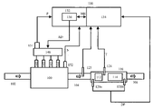
- FIG. 1 is a block diagram of the device according to the present invention.
- FIG. 2 is a block diagram for detecting the state of congestion according to the present invention.
- FIG. 3 illustrates a characteristic curve
- FIG. 4 is a block diagram of an example embodiment of the device according to the present invention.
- the device according to the present invention is described below, based on an example of an internal combustion engine having spontaneous ignition in which fuel metering is controlled by a common-rail system.
- the present invention is not limited to these systems. It may also be used with other internal combustion engines.
- An internal combustion engine 100 receives a supply of fresh air via an intake line 102 and discharges exhaust gases via an exhaust line 104 .
- An exhaust treatment unit 110 from which the cleaned exhaust gases pass through line 106 to the environment, is provided in exhaust line 104 .
- Exhaust treatment unit 110 includes a primary catalytic converter 112 and a downstream filter 114 .
- a temperature sensor 124 which provides a temperature signal T, may be located between primary catalytic converter 112 and filter 114 .
- Sensors 120 a and 120 b are provided upstream from primary catalytic converter 112 and downstream from filter 114 , respectively. These sensors act as differential-pressure sensors 120 and provide a differential-pressure signal DP, which characterizes the differential pressure between the inlet and outlet of the exhaust treatment unit.
- a sensor 125 may be provided to supply a signal characterizing the oxygen concentration in the exhaust gas. This quantity may be calculated on the basis of other measured values or be determined by a simulation.
- Fuel is supplied to internal combustion engine 100 via a fuel metering unit 140 .
- This unit meters fuel to the individual cylinders of internal combustion engine 100 via injectors 141 , 142 , 143 and 144 .
- the fuel metering unit may be a common rail system.
- a high-pressure pump delivers fuel to an accumulator. The fuel passes from the accumulator to the internal combustion engine via the injectors.
- Various sensors 151 which provide signals that characterize the status of the fuel metering unit, are attached to fuel metering unit 140 . In the case of a common rail system, these signals may include, for example, a pressure P in the accumulator. Sensors 152 that characterize the status of the internal combustion engine are attached to internal combustion engine 100 . These sensors may include a speed sensor that provides a speed signal N and additional sensors that are not illustrated.
- first control subsystem 132 may control fuel metering unit 140 via control signals AD, which influence fuel metering.
- first control subsystem 132 includes a fuel volume controller 136 .
- the fuel volume controller 136 supplies a signal ME, which characterizes the volume to be injected, to second control subsystem 134 .
- Second control subsystem 134 may control the exhaust treatment system, for which purpose it detects the corresponding sensor signals. Second control subsystem 134 also exchanges signals with first control subsystem 132 , including those relating to injected fuel volume ME. Both control systems may make mutual use of the sensor signals and internal signals.
- the first control subsystem which is also referred to as engine controller 132 , controls control signal AD for controlling fuel metering unit 140 as a function of various signals that characterize the operating state of fuel injection system 100 , the status of fuel metering system 140 and the ambient conditions, as well as a signal that characterizes the desired power output and/or torque.
- Devices of this type are conventional and are used in many different applications.
- exhaust treatment unit 110 In the case of diesel-powered internal combustion engines, particle emissions may occur in the exhaust gas.
- exhaust treatment unit 110 must filter these particles out of the exhaust gas. This filtering action causes particles to collect in filter 114 . To clean the filter, these particles are then burned in certain operating states and/or at the end of certain time periods. For this purpose, the temperature in exhaust treatment unit 110 is usually increased to the point at which the particles combust, thus regenerating filter 114 .
- Primary catalytic converter 112 is provided to increase the temperature. For example, the temperature is increased by increasing the proportion of uncombusted hydrocarbons in the exhaust gas. These uncombusted hydrocarbons then react in primary catalytic converter 112 , thereby increasing its temperature and thus also the temperature of the exhaust gas that enters filter 114 .
- One way to detect the state of congestion is to measure differential pressure DP between the inlet and outlet of the exhaust treatment unit 110 and to determine the state of congestion based on this value.
- Differential-pressure sensor 120 is provided for this purpose.
- the anticipated particle emissions are determined on the basis of different quantities, such as speed N and injected fuel volume ME, thereby simulating the state of congestion.
- filter 114 is regenerated by controlling fuel metering unit 140 .
- speed N and injected fuel volume ME other signals that characterize these quantities may also be used.
- a control signal such as a control duration for the injectors and/or a torque quantity, may be used as fuel volume ME.
- temperature T in the exhaust treatment system may be used to calculate the state of congestion.
- Sensor 124 may be used for this purpose.
- the quantity for the state of congestion calculated in this manner is then used to control the exhaust treatment system, i.e., regeneration is initiated by increasing the temperature, as a function of the state of congestion.
- the state of congestion may be measured via differential-pressure sensor 120 in addition to calculating the state of congestion.
- the system may be monitored for errors.
- Simulated quantity B and measured quantity BI of the state of congestion may be used to detect errors in the exhaust treatment system.
- an emergency mode may be implemented to control the exhaust treatment system, using the simulated quantity that characterizes the state of congestion.
- FIG. 2 is a block diagram illustrating a method and a device for detecting the state of congestion, i.e., quantity B, which characterizes the status of the exhaust treatment system, according to the present invention. Elements already described in FIG. 1 are identified by the same reference numbers.
- Output signals N of a speed sensor 152 , a quantity ME of fuel metering controller 136 , which characterizes the injected fuel volume, and/or a quantity characterizing the oxygen concentration, are supplied to a basic characteristic map 200 .
- the quantity characterizing the oxygen concentration may be measured by a sensor or determined by a calculation 125 .
- Basic characteristic map 200 applies a quantity GR, which characterizes the initial value of the particle emission, to a first node 205 .
- First node 205 applies a signal to a second node 210 , which, in turn, applies a quantity KR, which characterizes particle increment in filter 114 , to an integrator 220 .
- Integrator 220 supplies a quantity B, which characterizes the status of the exhaust treatment system. This quantity B corresponds to the state of congestion of filter 114 .
- Quantity B is provided to control system 130 .
- the output signal of a first adjustment element 230 to which is supplied the output signal of different sensors 235 , is present at the second input of node 205 .
- Sensors 235 supply signals that characterize the ambient conditions. These include cooling water temperature TW, air temperature and air pressure PL.
- the output signal of a second adjustment element 240 is supplied to the second input of node 210 via a switching unit 245 .
- Output signal T of sensor 124 is supplied to second adjustment element 240 .
- the output signal of a default-value generator 249 may also be supplied to the second input of second node 210 via switching unit 245 .
- Switching unit 245 is controlled by an error detector 248 .
- the oxygen concentration in the exhaust gas may be influenced with a further adjustment, corresponding to adjustment element 230 .
- Initial value GR of particle emission is stored in basic characteristic map 200 as a function of the operating state of the internal combustion engine, such as speed N, injected volume ME and/or the quantity characterizing the oxygen concentration.
- speed N and the quantity characterizing the oxygen concentration may be used, or speed N and injected volume ME may be used.
- volume ME a quantity that characterizes the volume of injected fuel may be used.
- This value is adjusted in first node 205 as a function of a temperature of the cooling water and ambient air as well as atmospheric pressure. This adjustment takes into account their influence on the particle emission of internal combustion engine 100 .
- the influence of the catalytic converter temperature is taken into account in second node 210 .
- the adjustment takes into account the fact that, above a certain temperature T 1 , the particles are not deposited in the filter but are directly converted to harmless components. Below this temperature T 1 , the particles are not converted, but are all deposited in the filter.
- second adjustment element 240 sets a factor F by which basic emission GR may be multiplied.
- FIG. 3 illustrates the correlation between factor F and temperature T.
- factor F assumes a value of 1.
- initial value GR is linked to factor F in node 210 so that value KR is equal to value GR.
- factor F decreases and reaches a value of zero at a certain temperature T 2 , i.e., the entire particle emission is converted directly to harmless components, thereby supplying no additional particles to filter 114 .
- T 3 the factor assumes a negative value of x, indicating a decrease in congestion of filter 114 , even though particles are being supplied to filter 114 .
- a default value from default-value generator 249 is used instead of temperature value T.
- This default value may be set as a function of different operating parameters, such as injected fuel volume ME.
- Value KR which has been adjusted in this manner and characterizes the particle value resulting in congestion of filter 114 , is supplied to integrator 220 .
- This integrator 220 sums up the quantity over time and emits a signal B that characterizes the state of congestion of filter 114 .
- the adjusted output signal of the basic characteristic map is integrated to determine state of congestion B of filter 114 .
- Signal B which characterizes the state of congestion of filter 114 , may be used directly to control the exhaust treatment system.
- the use of a simulated quantity eliminates the need for various sensors, including differential-pressure sensor 120 .
- the state of congestion is output from a characteristic map, based on at least the speed and/or the injected fuel volume or corresponding signals.
- the initial value determined in this manner is then adjusted. For example, it may be adjusted as a function of the temperature of the exhaust treatment unit, such as that of the particle filter. This adjustment takes into account continuous, temperature-dependent filter regeneration.
- FIG. 4 illustrates another example embodiment.
- Reference number 400 designates the simulation element illustrated in FIG. 2 to calculate state of congestion B.
- This simulation element 400 supplies a signal B for the state of congestion of filter 114 .
- a further calculation element 420 is provided, to which output signal DP of differential-pressure sensor 120 is supplied.
- Both simulation element 400 and calculation element 420 supply signals to a switching unit 410 , which selects one or another of the signals and provides it to control system 130 .
- Switching unit 410 is controlled by an error detector 415 .
- the exhaust treatment system is controlled during normal operation based on this state of congestion BI. If an error occurs in the exhaust treatment system, for example, when detecting or recording differential pressure DP, error detector 415 controls switching unit 410 so that signal B of simulation element 400 is used to control the exhaust treatment system.
- quantity (B) is used to control the exhaust treatment system.
- the system is controlled as a function of quantity (B), which characterizes the state of congestion, and/or additional signals.
- the simulated quantity may be used to implement a very accurate emergency mode. When used only in emergency mode, a simple simulation using only a few signals may be used.
- the plausibility of calculated quantity (BI) and simulated quantity (B) of the state of congestion may be checked and an error in the exhaust treatment system in the event of implausibility may be detected. Implausibility is detected, for example, when the difference between the two quantities is greater than a threshold value. This means that quantity (B) of the state of congestion is used to detect the error. This procedure is a simple and accurate error detection method.
Landscapes
- Engineering & Computer Science (AREA)
- Chemical & Material Sciences (AREA)
- Combustion & Propulsion (AREA)
- Mechanical Engineering (AREA)
- General Engineering & Computer Science (AREA)
- Analytical Chemistry (AREA)
- Chemical Kinetics & Catalysis (AREA)
- Exhaust Gas After Treatment (AREA)
- Processes For Solid Components From Exhaust (AREA)
- Combined Controls Of Internal Combustion Engines (AREA)
Applications Claiming Priority (3)
| Application Number | Priority Date | Filing Date | Title |
|---|---|---|---|
| DE19921299 | 1999-05-07 | ||
| DE10014224A DE10014224A1 (de) | 1999-05-07 | 2000-03-22 | Verfahren und Vorrichtung zur Steuerung einer Brennkraftmaschine mit einem Abgasnachbehandlungssytem |
| PCT/DE2000/001322 WO2000068557A1 (de) | 1999-05-07 | 2000-04-27 | Verfahren und vorrichtung zur steuerung einer brennkraftmaschine mit einem abgasnachbehandlungssystem |
Publications (1)
| Publication Number | Publication Date |
|---|---|
| US6968682B1 true US6968682B1 (en) | 2005-11-29 |
Family
ID=26004962
Family Applications (1)
| Application Number | Title | Priority Date | Filing Date |
|---|---|---|---|
| US10/030,888 Expired - Fee Related US6968682B1 (en) | 1999-05-07 | 2000-04-27 | Method and device for controlling an internal combustion engine with an exhaust treatment system |
Country Status (4)
| Country | Link |
|---|---|
| US (1) | US6968682B1 (de) |
| EP (1) | EP1180210B2 (de) |
| JP (1) | JP2002544423A (de) |
| WO (1) | WO2000068557A1 (de) |
Cited By (3)
| Publication number | Priority date | Publication date | Assignee | Title |
|---|---|---|---|---|
| US20050267670A1 (en) * | 2004-06-01 | 2005-12-01 | Siemens Ag | Method for monitoring a particle filter |
| US8418441B2 (en) | 2009-05-29 | 2013-04-16 | Corning Incorporated | Systems and methods for controlling temperature and total hydrocarbon slip |
| CN114033532A (zh) * | 2021-11-08 | 2022-02-11 | 凯龙高科技股份有限公司 | Dpf主动再生周期确定方法、装置、电子设备及存储介质 |
Families Citing this family (7)
| Publication number | Priority date | Publication date | Assignee | Title |
|---|---|---|---|---|
| JP2002256846A (ja) * | 2001-02-28 | 2002-09-11 | Bosch Automotive Systems Corp | フィルタ制御装置 |
| JP4470593B2 (ja) | 2004-06-03 | 2010-06-02 | 株式会社デンソー | 内燃機関の排気浄化装置 |
| CN100491704C (zh) * | 2004-08-10 | 2009-05-27 | 日产自动车株式会社 | 柴油机微粒滤清器中微粒沉积量的推算装置及方法 |
| DE102006018956B4 (de) | 2006-04-24 | 2024-11-21 | Robert Bosch Gmbh | Verfahren zur Diagnose eines Partikelfilters |
| DE102006061936A1 (de) * | 2006-12-29 | 2008-07-03 | Robert Bosch Gmbh | Verfahren und System zur Simulation des Betriebs einer Brennkraftmaschine |
| DE102007009841A1 (de) | 2007-03-01 | 2008-09-04 | Robert Bosch Gmbh | Verfahren und Vorrichtung zur Ermittlung eines Beladungszustandes eines Partikelfilters |
| ES2376758T3 (es) | 2007-08-30 | 2012-03-16 | Robert Bosch Gmbh | Sensor de gas de escape |
Citations (24)
| Publication number | Priority date | Publication date | Assignee | Title |
|---|---|---|---|---|
| JPS56510A (en) * | 1979-06-14 | 1981-01-07 | Nissan Motor Co Ltd | Exhaust gas purifying system for internal-combustion engine |
| US4404795A (en) * | 1980-06-19 | 1983-09-20 | Toyota Jidosha Kogyo Kabushiki Kaisha | Method of and apparatus for reducing emitted amount of particulates contained in exhaust gas of diesel engine |
| US4462208A (en) * | 1982-09-23 | 1984-07-31 | General Motors Corporation | Regeneration control system for a diesel engine exhaust particulate filter |
| US4574589A (en) * | 1982-12-24 | 1986-03-11 | Nissan Motor Company, Limited | Exhaust particle removing system for an internal combustion engine |
| US4615172A (en) * | 1984-02-21 | 1986-10-07 | Bbc Brown, Boveri & Company, Limited | Process for regenerating the exhaust-gas particle filter of internal-combustion engines |
| EP0260031A1 (de) | 1986-08-28 | 1988-03-16 | AlliedSignal Inc. | System zum Regenerieren eines Partikelfilters eines Motors |
| DE3723470A1 (de) | 1987-07-16 | 1989-01-26 | Kloeckner Humboldt Deutz Ag | Verfahren zur steuerung der regenerierung eines russfilters |
| DE3832790A1 (de) | 1988-09-27 | 1990-03-29 | Pattas Konstantin N | Verfahren und einrichtung zum regenerieren eines russfilters |
| US5097665A (en) * | 1988-11-01 | 1992-03-24 | Kammel Refaat A | Flattened profile diesel engine exhaust oxidizer |
| US5121601A (en) * | 1986-10-21 | 1992-06-16 | Kammel Refaat A | Diesel engine exhaust oxidizer |
| JPH0544439A (ja) * | 1991-08-20 | 1993-02-23 | Nissan Motor Co Ltd | デイーゼル機関の排気浄化装置 |
| US5195316A (en) * | 1989-12-27 | 1993-03-23 | Nissan Motor Co., Ltd. | Exhaust gas purifying device for an internal combustion engine |
| US5195318A (en) * | 1989-12-28 | 1993-03-23 | Nissan Motor Co., Ltd. | Exhaust gas purifying device for an internal combustion engine |
| DE4230180A1 (de) | 1992-09-09 | 1994-03-10 | Eberspaecher J | Verfahren und Vorrichtung zur Ermittlung des Beladungszustands von Partikelfiltern |
| JPH0734924A (ja) | 1993-07-16 | 1995-02-03 | Toyota Motor Corp | 内燃機関の燃料噴射量制御装置 |
| US5458673A (en) * | 1992-11-26 | 1995-10-17 | Nippon Soken, Inc. | Exhaust gas particulate purifying process for internal combustion engine |
| JPH0835418A (ja) | 1994-07-25 | 1996-02-06 | Nippondenso Co Ltd | 排出ガス浄化装置の温度制御装置 |
| US5647669A (en) | 1994-07-14 | 1997-07-15 | Robert Bosch Gmbh | Method for generating a simulated signal relating to a temperature in the exhaust system of an internal combustion engine |
| US5746989A (en) * | 1995-08-14 | 1998-05-05 | Toyota Jidosha Kabushiki Kaisha | Method for purifying exhaust gas of a diesel engine |
| US5850735A (en) * | 1995-09-11 | 1998-12-22 | Toyota Jidosha Kabushiki Kaisha | Method for purifying exhaust gas of an internal combustion engine |
| DE19838032A1 (de) | 1997-09-16 | 1999-03-18 | Avl List Gmbh | Verfahren zur Regeneration eines Partikelfilters |
| DE19744067A1 (de) | 1997-10-06 | 1999-04-08 | Bosch Gmbh Robert | Temperaturmodellbildung für den Abgasbereich eines Verbrennungsmotors |
| JPH11117786A (ja) | 1997-10-17 | 1999-04-27 | Mitsubishi Motors Corp | 内燃機関の排気浄化装置 |
| DE19906287A1 (de) | 1999-02-15 | 2000-08-17 | Bosch Gmbh Robert | Verfahren und Steuerung einer Brennkraftmaschine mit einem Abgasnachbehandlungssystems |
Family Cites Families (9)
| Publication number | Priority date | Publication date | Assignee | Title |
|---|---|---|---|---|
| JPH0713452B2 (ja) * | 1987-09-17 | 1995-02-15 | トヨタ自動車株式会社 | 内燃機関の排気粒子捕集器の粒子捕集量検出装置 |
| JPH0569312U (ja) * | 1992-02-28 | 1993-09-21 | 三菱自動車工業株式会社 | パティキュレート補集量測定装置 |
| JPH05312020A (ja) * | 1992-05-01 | 1993-11-22 | Toyota Motor Corp | 内燃機関の排気浄化装置 |
| JP3116549B2 (ja) * | 1992-05-27 | 2000-12-11 | 日産自動車株式会社 | エンジンの排気浄化装置 |
| JPH0734851A (ja) * | 1993-07-22 | 1995-02-03 | Nissan Motor Co Ltd | ディーゼル機関の排気浄化装置 |
| JPH0734858A (ja) * | 1993-07-26 | 1995-02-03 | Nissan Motor Co Ltd | ディーゼル機関の排気浄化装置 |
| JPH10184343A (ja) * | 1996-12-24 | 1998-07-14 | Toyota Autom Loom Works Ltd | ディーゼルエンジンの排気ガス浄化装置 |
| DE19714293C1 (de) * | 1997-04-07 | 1998-09-03 | Siemens Ag | Verfahren zum Überprüfen der Konvertierungsfähigkeit eines Katalysators |
| JP2000170521A (ja) * | 1998-12-08 | 2000-06-20 | Toyota Motor Corp | パティキュレートフィルタの捕集量算出方法及び再生方法 |
-
2000
- 2000-04-27 JP JP2000617316A patent/JP2002544423A/ja active Pending
- 2000-04-27 EP EP00941887A patent/EP1180210B2/de not_active Expired - Lifetime
- 2000-04-27 US US10/030,888 patent/US6968682B1/en not_active Expired - Fee Related
- 2000-04-27 WO PCT/DE2000/001322 patent/WO2000068557A1/de not_active Ceased
Patent Citations (26)
| Publication number | Priority date | Publication date | Assignee | Title |
|---|---|---|---|---|
| JPS56510A (en) * | 1979-06-14 | 1981-01-07 | Nissan Motor Co Ltd | Exhaust gas purifying system for internal-combustion engine |
| US4404795A (en) * | 1980-06-19 | 1983-09-20 | Toyota Jidosha Kogyo Kabushiki Kaisha | Method of and apparatus for reducing emitted amount of particulates contained in exhaust gas of diesel engine |
| US4462208A (en) * | 1982-09-23 | 1984-07-31 | General Motors Corporation | Regeneration control system for a diesel engine exhaust particulate filter |
| US4574589A (en) * | 1982-12-24 | 1986-03-11 | Nissan Motor Company, Limited | Exhaust particle removing system for an internal combustion engine |
| US4615172A (en) * | 1984-02-21 | 1986-10-07 | Bbc Brown, Boveri & Company, Limited | Process for regenerating the exhaust-gas particle filter of internal-combustion engines |
| EP0260031A1 (de) | 1986-08-28 | 1988-03-16 | AlliedSignal Inc. | System zum Regenerieren eines Partikelfilters eines Motors |
| US5121601A (en) * | 1986-10-21 | 1992-06-16 | Kammel Refaat A | Diesel engine exhaust oxidizer |
| DE3723470A1 (de) | 1987-07-16 | 1989-01-26 | Kloeckner Humboldt Deutz Ag | Verfahren zur steuerung der regenerierung eines russfilters |
| DE3832790A1 (de) | 1988-09-27 | 1990-03-29 | Pattas Konstantin N | Verfahren und einrichtung zum regenerieren eines russfilters |
| US5097665A (en) * | 1988-11-01 | 1992-03-24 | Kammel Refaat A | Flattened profile diesel engine exhaust oxidizer |
| US5287698A (en) * | 1989-12-27 | 1994-02-22 | Nissan Motor Co., Ltd. | Exhaust gas purifying device for an internal combustion engine |
| US5319930A (en) * | 1989-12-27 | 1994-06-14 | Nissan Motor Co., Ltd. | Exhaust gas purifying device for an internal combustion engine |
| US5195316A (en) * | 1989-12-27 | 1993-03-23 | Nissan Motor Co., Ltd. | Exhaust gas purifying device for an internal combustion engine |
| US5195318A (en) * | 1989-12-28 | 1993-03-23 | Nissan Motor Co., Ltd. | Exhaust gas purifying device for an internal combustion engine |
| JPH0544439A (ja) * | 1991-08-20 | 1993-02-23 | Nissan Motor Co Ltd | デイーゼル機関の排気浄化装置 |
| DE4230180A1 (de) | 1992-09-09 | 1994-03-10 | Eberspaecher J | Verfahren und Vorrichtung zur Ermittlung des Beladungszustands von Partikelfiltern |
| US5458673A (en) * | 1992-11-26 | 1995-10-17 | Nippon Soken, Inc. | Exhaust gas particulate purifying process for internal combustion engine |
| JPH0734924A (ja) | 1993-07-16 | 1995-02-03 | Toyota Motor Corp | 内燃機関の燃料噴射量制御装置 |
| US5647669A (en) | 1994-07-14 | 1997-07-15 | Robert Bosch Gmbh | Method for generating a simulated signal relating to a temperature in the exhaust system of an internal combustion engine |
| JPH0835418A (ja) | 1994-07-25 | 1996-02-06 | Nippondenso Co Ltd | 排出ガス浄化装置の温度制御装置 |
| US5746989A (en) * | 1995-08-14 | 1998-05-05 | Toyota Jidosha Kabushiki Kaisha | Method for purifying exhaust gas of a diesel engine |
| US5850735A (en) * | 1995-09-11 | 1998-12-22 | Toyota Jidosha Kabushiki Kaisha | Method for purifying exhaust gas of an internal combustion engine |
| DE19838032A1 (de) | 1997-09-16 | 1999-03-18 | Avl List Gmbh | Verfahren zur Regeneration eines Partikelfilters |
| DE19744067A1 (de) | 1997-10-06 | 1999-04-08 | Bosch Gmbh Robert | Temperaturmodellbildung für den Abgasbereich eines Verbrennungsmotors |
| JPH11117786A (ja) | 1997-10-17 | 1999-04-27 | Mitsubishi Motors Corp | 内燃機関の排気浄化装置 |
| DE19906287A1 (de) | 1999-02-15 | 2000-08-17 | Bosch Gmbh Robert | Verfahren und Steuerung einer Brennkraftmaschine mit einem Abgasnachbehandlungssystems |
Non-Patent Citations (3)
| Title |
|---|
| Patent Abstracts of Japan, vol. 1995, No. 05, Jun. 30, 1995. |
| Patent Abstracts of Japan, vol. 1996, No. 06, Jun. 28, 1996. |
| Patent Abstracts of Japan, vol. 1999, No. 09, Jul. 30, 1999. |
Cited By (6)
| Publication number | Priority date | Publication date | Assignee | Title |
|---|---|---|---|---|
| US20050267670A1 (en) * | 2004-06-01 | 2005-12-01 | Siemens Ag | Method for monitoring a particle filter |
| US7340887B2 (en) | 2004-06-01 | 2008-03-11 | Siemens Aktiengesellschaft | Method for monitoring a particle filter |
| US8418441B2 (en) | 2009-05-29 | 2013-04-16 | Corning Incorporated | Systems and methods for controlling temperature and total hydrocarbon slip |
| US8793980B2 (en) | 2009-05-29 | 2014-08-05 | Corning Incorporated | Systems and methods for controlling temperature and total hydrocarbon slip |
| CN114033532A (zh) * | 2021-11-08 | 2022-02-11 | 凯龙高科技股份有限公司 | Dpf主动再生周期确定方法、装置、电子设备及存储介质 |
| CN114033532B (zh) * | 2021-11-08 | 2022-12-30 | 凯龙高科技股份有限公司 | Dpf主动再生周期确定方法、装置、电子设备及存储介质 |
Also Published As
| Publication number | Publication date |
|---|---|
| EP1180210B1 (de) | 2004-06-30 |
| EP1180210B2 (de) | 2006-11-22 |
| EP1180210A1 (de) | 2002-02-20 |
| JP2002544423A (ja) | 2002-12-24 |
| WO2000068557A1 (de) | 2000-11-16 |
Similar Documents
| Publication | Publication Date | Title |
|---|---|---|
| EP1528229B1 (de) | Filtersteuerverfahren und -vorrichtung | |
| KR100819229B1 (ko) | 배기가스 후처리 시스템의 제어를 위한 방법 및 장치 | |
| US6952953B2 (en) | Method and device for monitoring a sensor | |
| EP1529931B1 (de) | Filtersteuervorrichtung | |
| CN101344043B (zh) | 排气氧传感器性能的监测 | |
| JP4445314B2 (ja) | コンピューターによる圧力センサーの診断システム及び方法 | |
| US7310941B2 (en) | Exhaust gas purification system for internal combustion engine | |
| US7104049B2 (en) | Exhaust gas purifying system and regeneration end determining method | |
| US20030106303A1 (en) | Method and device for the control of an exhaust gas treatment system | |
| EP1467071A1 (de) | Abgasreinigungsvorrichtung für Brennkraftmaschinen | |
| EP1455060B1 (de) | Motorabgasreinigungsvorrichtung | |
| KR102354297B1 (ko) | 가솔린 작동식 내연기관의 배기가스 시스템에 배열된 입자 필터를 진단하는 방법 및 장치 | |
| US7325395B2 (en) | Exhaust gas purification device of internal combustion engine | |
| US11585258B2 (en) | Method for determining the loading of a soot filter | |
| US6968682B1 (en) | Method and device for controlling an internal combustion engine with an exhaust treatment system | |
| US7055309B2 (en) | Method and device for controlling an internal combustion engine | |
| JP3908204B2 (ja) | フィルタ制御装置 | |
| KR102324288B1 (ko) | 가솔린 작동식 내연기관의 배기가스 시스템에 배열된 입자 필터를 진단하는 방법 및 장치 | |
| JP3999613B2 (ja) | 内燃機関の制御方法および制御装置 | |
| JPH0933478A (ja) | 内燃機関における酸素センサの応答診断装置 | |
| JPS59113232A (ja) | 排気微粒子処理装置の作動制御装置 | |
| JP3608255B2 (ja) | 内燃機関の排気ガス浄化装置の目詰まり検出方法 | |
| KR20060070198A (ko) | 디젤 엔진의 동적 스모크 배출량 계산 방법 |
Legal Events
| Date | Code | Title | Description |
|---|---|---|---|
| AS | Assignment |
Owner name: ROBERT BOSCH GMBH, GERMANY Free format text: ASSIGNMENT OF ASSIGNORS INTEREST;ASSIGNORS:LEUZ, MARKUS;PFAEFFLE, ANDREAS;SCHERNEWSKI, RALF;REEL/FRAME:013002/0811;SIGNING DATES FROM 20011123 TO 20011129 |
|
| FPAY | Fee payment |
Year of fee payment: 4 |
|
| FPAY | Fee payment |
Year of fee payment: 8 |
|
| REMI | Maintenance fee reminder mailed | ||
| LAPS | Lapse for failure to pay maintenance fees |
Free format text: PATENT EXPIRED FOR FAILURE TO PAY MAINTENANCE FEES (ORIGINAL EVENT CODE: EXP.) |
|
| STCH | Information on status: patent discontinuation |
Free format text: PATENT EXPIRED DUE TO NONPAYMENT OF MAINTENANCE FEES UNDER 37 CFR 1.362 |
|
| FP | Lapsed due to failure to pay maintenance fee |
Effective date: 20171129 |