US6968997B2 - Banknote receipt and payout apparatus - Google Patents
Banknote receipt and payout apparatus Download PDFInfo
- Publication number
- US6968997B2 US6968997B2 US10/424,069 US42406903A US6968997B2 US 6968997 B2 US6968997 B2 US 6968997B2 US 42406903 A US42406903 A US 42406903A US 6968997 B2 US6968997 B2 US 6968997B2
- Authority
- US
- United States
- Prior art keywords
- banknote
- banknotes
- receipt
- loading
- denominations
- Prior art date
- Legal status (The legal status is an assumption and is not a legal conclusion. Google has not performed a legal analysis and makes no representation as to the accuracy of the status listed.)
- Expired - Fee Related
Links
Images




Classifications
-
- B—PERFORMING OPERATIONS; TRANSPORTING
- B65—CONVEYING; PACKING; STORING; HANDLING THIN OR FILAMENTARY MATERIAL
- B65H—HANDLING THIN OR FILAMENTARY MATERIAL, e.g. SHEETS, WEBS, CABLES
- B65H33/00—Forming counted batches in delivery pile or stream of articles
- B65H33/06—Forming counted batches in delivery pile or stream of articles by displacing articles to define batches
- B65H33/10—Displacing the end articles of a batch
-
- G—PHYSICS
- G07—CHECKING-DEVICES
- G07D—HANDLING OF COINS OR VALUABLE PAPERS, e.g. TESTING, SORTING BY DENOMINATIONS, COUNTING, DISPENSING, CHANGING OR DEPOSITING
- G07D9/00—Counting coins; Handling of coins not provided for in the other groups of this subclass
-
- B—PERFORMING OPERATIONS; TRANSPORTING
- B65—CONVEYING; PACKING; STORING; HANDLING THIN OR FILAMENTARY MATERIAL
- B65H—HANDLING THIN OR FILAMENTARY MATERIAL, e.g. SHEETS, WEBS, CABLES
- B65H1/00—Supports or magazines for piles from which articles are to be separated
- B65H1/02—Supports or magazines for piles from which articles are to be separated adapted to support articles on edge
- B65H1/025—Supports or magazines for piles from which articles are to be separated adapted to support articles on edge with controlled positively-acting mechanical devices for advancing the pile to present the articles to the separating device
-
- B—PERFORMING OPERATIONS; TRANSPORTING
- B65—CONVEYING; PACKING; STORING; HANDLING THIN OR FILAMENTARY MATERIAL
- B65H—HANDLING THIN OR FILAMENTARY MATERIAL, e.g. SHEETS, WEBS, CABLES
- B65H1/00—Supports or magazines for piles from which articles are to be separated
- B65H1/02—Supports or magazines for piles from which articles are to be separated adapted to support articles on edge
- B65H1/027—Support fully or partially removable from the handling machine, e.g. cassette, drawer
-
- B—PERFORMING OPERATIONS; TRANSPORTING
- B65—CONVEYING; PACKING; STORING; HANDLING THIN OR FILAMENTARY MATERIAL
- B65H—HANDLING THIN OR FILAMENTARY MATERIAL, e.g. SHEETS, WEBS, CABLES
- B65H3/00—Separating articles from piles
- B65H3/02—Separating articles from piles using friction forces between articles and separator
- B65H3/06—Rollers or like rotary separators
- B65H3/0653—Rollers or like rotary separators for separating substantially vertically stacked articles
-
- B—PERFORMING OPERATIONS; TRANSPORTING
- B65—CONVEYING; PACKING; STORING; HANDLING THIN OR FILAMENTARY MATERIAL
- B65H—HANDLING THIN OR FILAMENTARY MATERIAL, e.g. SHEETS, WEBS, CABLES
- B65H83/00—Combinations of piling and depiling operations, e.g. performed simultaneously, of interest apart from the single operation of piling or depiling as such
- B65H83/02—Combinations of piling and depiling operations, e.g. performed simultaneously, of interest apart from the single operation of piling or depiling as such performed on the same pile or stack
- B65H83/025—Combinations of piling and depiling operations, e.g. performed simultaneously, of interest apart from the single operation of piling or depiling as such performed on the same pile or stack onto and from the same side of the pile or stack
-
- G—PHYSICS
- G06—COMPUTING OR CALCULATING; COUNTING
- G06Q—INFORMATION AND COMMUNICATION TECHNOLOGY [ICT] SPECIALLY ADAPTED FOR ADMINISTRATIVE, COMMERCIAL, FINANCIAL, MANAGERIAL OR SUPERVISORY PURPOSES; SYSTEMS OR METHODS SPECIALLY ADAPTED FOR ADMINISTRATIVE, COMMERCIAL, FINANCIAL, MANAGERIAL OR SUPERVISORY PURPOSES, NOT OTHERWISE PROVIDED FOR
- G06Q20/00—Payment architectures, schemes or protocols
- G06Q20/08—Payment architectures
- G06Q20/10—Payment architectures specially adapted for electronic funds transfer [EFT] systems; specially adapted for home banking systems
- G06Q20/108—Remote banking, e.g. home banking
- G06Q20/1085—Remote banking, e.g. home banking involving automatic teller machines [ATMs]
-
- G—PHYSICS
- G07—CHECKING-DEVICES
- G07D—HANDLING OF COINS OR VALUABLE PAPERS, e.g. TESTING, SORTING BY DENOMINATIONS, COUNTING, DISPENSING, CHANGING OR DEPOSITING
- G07D11/00—Devices accepting coins; Devices accepting, dispensing, sorting or counting valuable papers
- G07D11/10—Mechanical details
- G07D11/12—Containers for valuable papers
- G07D11/13—Containers for valuable papers with internal means for handling valuable papers
-
- G—PHYSICS
- G07—CHECKING-DEVICES
- G07D—HANDLING OF COINS OR VALUABLE PAPERS, e.g. TESTING, SORTING BY DENOMINATIONS, COUNTING, DISPENSING, CHANGING OR DEPOSITING
- G07D11/00—Devices accepting coins; Devices accepting, dispensing, sorting or counting valuable papers
- G07D11/20—Controlling or monitoring the operation of devices; Data handling
- G07D11/24—Managing the inventory of valuable papers
- G07D11/245—Replenishment
-
- G—PHYSICS
- G07—CHECKING-DEVICES
- G07D—HANDLING OF COINS OR VALUABLE PAPERS, e.g. TESTING, SORTING BY DENOMINATIONS, COUNTING, DISPENSING, CHANGING OR DEPOSITING
- G07D11/00—Devices accepting coins; Devices accepting, dispensing, sorting or counting valuable papers
- G07D11/20—Controlling or monitoring the operation of devices; Data handling
- G07D11/24—Managing the inventory of valuable papers
- G07D11/25—Relocation of valuable papers within devices
-
- G—PHYSICS
- G07—CHECKING-DEVICES
- G07D—HANDLING OF COINS OR VALUABLE PAPERS, e.g. TESTING, SORTING BY DENOMINATIONS, COUNTING, DISPENSING, CHANGING OR DEPOSITING
- G07D11/00—Devices accepting coins; Devices accepting, dispensing, sorting or counting valuable papers
- G07D11/40—Device architecture, e.g. modular construction
-
- G—PHYSICS
- G07—CHECKING-DEVICES
- G07F—COIN-FREED OR LIKE APPARATUS
- G07F19/00—Complete banking systems; Coded card-freed arrangements adapted for dispensing or receiving monies or the like and posting such transactions to existing accounts, e.g. automatic teller machines
- G07F19/20—Automatic teller machines [ATMs]
-
- G—PHYSICS
- G07—CHECKING-DEVICES
- G07F—COIN-FREED OR LIKE APPARATUS
- G07F19/00—Complete banking systems; Coded card-freed arrangements adapted for dispensing or receiving monies or the like and posting such transactions to existing accounts, e.g. automatic teller machines
- G07F19/20—Automatic teller machines [ATMs]
- G07F19/205—Housing aspects of ATMs
-
- B—PERFORMING OPERATIONS; TRANSPORTING
- B65—CONVEYING; PACKING; STORING; HANDLING THIN OR FILAMENTARY MATERIAL
- B65H—HANDLING THIN OR FILAMENTARY MATERIAL, e.g. SHEETS, WEBS, CABLES
- B65H2301/00—Handling processes for sheets or webs
- B65H2301/40—Type of handling process
- B65H2301/42—Piling, depiling, handling piles
- B65H2301/421—Forming a pile
- B65H2301/4214—Forming a pile of articles on edge
- B65H2301/42142—Forming a pile of articles on edge by introducing articles from beneath
-
- B—PERFORMING OPERATIONS; TRANSPORTING
- B65—CONVEYING; PACKING; STORING; HANDLING THIN OR FILAMENTARY MATERIAL
- B65H—HANDLING THIN OR FILAMENTARY MATERIAL, e.g. SHEETS, WEBS, CABLES
- B65H2405/00—Parts for holding the handled material
- B65H2405/30—Other features of supports for sheets
- B65H2405/31—Supports for sheets fully removable from the handling machine, e.g. cassette
- B65H2405/313—Supports for sheets fully removable from the handling machine, e.g. cassette with integrated handling means, e.g. separating means
Definitions
- the present invention relates to a banknote receipt and payout apparatus for using receipt bank-notes as payout banknotes.
- JP-A-11-110607 discloses a configuration capable of handling several denominations of banknotes.
- This configuration of prior art incorporates a mechanism portion composed of a receipt and payout opening, a temporary storage bin, a banknote checking part and the like, and the mechanism portion is coupled with several banknote storage bins through the intermediary of a loop-like transfer path.
- an automatic teller machine is composed of an upper mechanism portion including the receipt and payout opening, the temporary storage bin and the banknote checking part, and a safe-like lower mechanism part composed of the banknote storage bins accommodated in a housing.
- an automatic teller machine in which several banknote storage bins are arranged, being juxtaposed in the case of a large number of banknote storage bins.
- the automatic teller machine discloses in the above-mentioned document JP-A-11-110607 has such a structure that several banknote storage bins are arranged being juxtaposed in order to increase the number of denominations of banknotes to be handled.
- the loading of banknotes into the teller machine is carried out in such a way that a loading and collecting bin in which the banknotes are stacked is mounted in the teller machine, and then the banknotes are transferred from the loading and collecting bin into the banknote cassettes. Further, the collection of the banknotes from the teller machine is carried out such a way that the banknotes from the banknotes cassettes are transferred and stored into an empty loading and collecting bin which is installed in the teller machine.
- the above-mentioned loading and collecting bin has to handle a plurality of denominations, that is, intermingled banknotes to be stored and discharged, having different sizes.
- a vertical loading and collecting bin in which the banknotes are stacked in a horizontal posture, if banknotes having different sizes are stored therein, banknotes having a smaller size are not restrained within the banknote loading and collecting bin, and accordingly, they are stacked in disorder, thereby normal execute operation becomes impossible.
- the loading and collecting bin must be sidelong so that the banknotes are stacked in a standing posture and are aligned at their lower end.
- An object of the present invention is to provide a banknote receipt and payout apparatus which can handle a large number of denominations of banknotes, which has a function capable of loading and collecting banknotes and which can accept several denominations of banknotes.
- a banknote receipt and payout apparatus comprising an receipt and payout opening for carrying out either or both of payout and stacking of charged banknotes, a banknote checking part for checking denominations of the banknotes, at least one of banknote storage and discharge bins for carrying out either or both of storage and discharge of the banknotes, a transfer path connecting the receipt and payout opening, the banknote checking part and the banknote storage and discharge bins to one another, for transferring the banknotes, and a loading and collecting bin for loading and collecting the banknotes into and from the banknote storage and discharge bin, wherein the banknote storage and discharge bin stacks therein banknotes in a vertical direction, and the loading and collecting bin stacks therein banknotes in a horizontal direction therein with a standing posture.
- the above-mentioned object can be achieved by the above-mentioned loading and collecting bin which can be pulled out from the banknote receipt and payout apparatus.
- banknote storage and discharge bins having a number corresponding to a number of denominations of banknotes to be handed, and arranged being horizontally juxtaposed.
- the above-mentioned object can be achieved by the loading and collecting bin which can be taken out from the banknote receipt and payout apparatus, longitudinally thereof.
- FIG. 1 is an external perspective view illustrating an automatic teller machine to which the present invention is applied;
- FIG. 2 is a block diagram illustrating a control mechanism in the automatic teller machine to which the present invention is applied;
- FIG. 3 is a sectional view illustrating a banknote receipt and payout apparatus
- FIG. 4 is a block diagram illustrating a control mechanism in the banknote receipt and payout apparatus incorporating an embodiment
- FIG. 5 is a section view illustrating the banknote receipt and payout apparatus during receipt operation in an embodiment
- FIG. 6 is a section view illustrating the banknote receipt and payout apparatus during receipt operation in an embodiment
- FIG. 7 is a flow chart for receipt operation in an embodiment
- FIG. 8 is a sectional view illustrating a banknote receipt and payout apparatus during payout operation in an embodiment
- FIG. 9 is a flow chart for payout operation in an embodiment
- FIG. 10 is a sectional view illustrating a banknote receipt and payout apparatus during banknote loading operation in an embodiment
- FIG. 11 is a flow chart for banknote loading operation in an embodiment
- FIG. 12 is a sectional view illustrating the banknote receipt and payout apparatus during banknote collecting operation in an embodiment
- FIG. 13 is a flow chart for banknote collecting operation in an embodiment
- FIG. 14 is a top view illustrating a loading and collecting bin which is installed in the banknote receipt and payout apparatus
- FIG. 15 is a side view illustrating a loading and collecting bin during such an operation that banknotes are stored in the loading and collecting bin;
- FIG. 16 is a side view illustrating the loading and collecting bin during such an operation that banknotes are discharged form the loading and collecting bin;
- FIG. 17 is a view illustrating a configuration of a stack assist member
- FIG. 18 is a side view illustrating the banknote storage and discharge bin during such an operation that banknotes are stored therein;
- FIG. 19 is a side view illustrating the banknote storage and discharge bin during such an operation that banknotes are stored therefrom;
- FIG. 20 is a configuration view illustrating a banknote receipt and payout apparatus incorporating another embodiment
- FIG. 21 is a configuration view illustrating a banknote receipt and payout apparatus incorporating another embodiment
- FIG. 22 is a configuration view illustrating a banknote receipt and payout apparatus incorporating another embodiment
- FIG. 23 is a configuration view illustrating a banknote receipt and payout apparatus incorporating another embodiment
- FIG. 24 is a configuration view illustrating a banknote receipt and payout apparatus incorporating another embodiment
- FIG. 25 is a configuration view illustrating a banknote receipt and payout apparatus incorporating another embodiment
- FIG. 26 is a flow chart for a banknote receipt and payout apparatus incorporating another embodiment.
- FIG. 27 is a flow chart for a banknote receipt and payout apparatus incorporating another embodiment.
- FIG. 1 is a view of illustrating an external appearance of an automatic teller machine in which the present invention is applied.
- the automatic teller machine 102 in this embodiment is composed of a card/slip processing mechanism 101 for processing a customer's transaction card or a transaction slip a bankbook processing mechanism 103 for processing a bankbook, a housing 104 , a customer manipulation panel 105 through which data required for transaction is displayed and inputted, and a banknote receipt and payout apparatus 1 .
- Reference numeral 106 denotes a main control portion for controlling the operation of the banknote receipt and payout apparatus 1 .
- FIG. 2 is a block diagram which shows a control relationship in the automatic teller machine 101 .
- the card/slip processing mechanism 102 , the bankbook processing mechanism 103 , the customer manipulation panel 105 and the banknote receipt and payout apparatus 1 are connected to the main control portion 106 through the intermediary of a bus 110 , and are operated under the control of the main control portion 106 .
- an interface portion 107 , an operator manipulation panel 108 and an external storage unit 109 are also connected to the main control portion 106 so as to transmit required data thereamong, but detailed description will be omitted. It is noted that the above-mentioned mechanisms and components are fed with a power from a power source 111 .
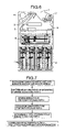
- FIG. 3 is a configuration of the banknote receipt and payout apparatus 1 mounted in the automatic teller machine 101
- FIG. 4 is a block diagram which shows a control mechanism.
- the banknote receipt and payout apparatus 1 comprises a receipt and payout opening 2 for charging and discharging banknotes, a banknote checking part 3 for determining a denomination of a banknote or checking whether a banknote is true or false, a temporary storage part 4 for temporarily storing therein a charged banknote until completion of transaction, a transfer path 5 coupling the components in the banknote receipt and payout apparatus 1 with one another for transferring banknotes, and banknote cassettes in which banknotes to be handled in the banknote receipt and payout apparatus 1 are stopped.
- These banknote cassettes are classified in view their roles.
- a receipt bin is a storage bin for banknotes which are determined to be received therein but not paid out therefrom as being inappropriate for payout as it is folded or broken. Further, this receipt bin is used for receipt of a banknote but do not for payout the banknote such as a five thousand yen banknote.
- this receipt bin If this receipt bin is used for foreign currency banknotes having different sizes among several denominations, it receives banknotes having various sizes. However, it is not necessary to align the banknotes at its one side end since the banknotes received therein will not be used as payout banknotes, and accordingly, they may be simply stacked one upon another. Accordingly, this receipt bin may be of a vertical type.
- the storage and discharge bins are safes for storing and discharge banknotes having different denominations, respectively, for receipt and payout thereof. For example, one of them is for thousand yen banknotes, and another one of them is for ten thousand yen banknotes or the like.
- the loading and collecting bin is a safe for carrying out loading and collection, which is a bank-note cassette for storing and discharging intermingled banknotes to be handled in the banknote receipt and payout apparatus 1 .
- the receipt bin 6 , the storage and discharge bins 7 and the loading and collecting bin 8 there are incorporated the receipt bin 6 , the storage and discharge bins 7 and the loading and collecting bin 8 , and in the embodiment as shown in FIG. 3 , the receipt bin 6 and the storage and discharge bins 7 are banknotes cassettes which are of vertical type, in which banknotes are stored in a horizontal posture.
- the loading and collecting bin 8 is a horizontal banknote cassette 7 in which banknotes are stored in a standing posture.
- the loading and collecting bin 8 can be slid toward the left side and the right side in FIG. 3 so as to be taken out from the banknote receipt and payout apparatus 1 .
- the operator can take out the loading and collecting bin 8 from the front part or the rear part of the automatic teller machine 101 after banknotes remaining in the receipt bin 6 and the banknote storage and discharge bins 7 are collected in the loading and collecting bin 8 , and then the operator keeps the loading and collecting bin 8 to be in custody at a predetermined place.
- the loading and collecting bin 8 in custody is returned into the automatic teller machine 101 before a start of the service in the next morning, and banknotes are stored in the receipt bin 6 and the banknote storage and discharge bin 7 .
- Japanese currency banknotes including a thousand yen banknote and a ten thousand banknote have one and the same size in the short side direction, and accordingly, the Japanese currency banknotes can be vertically stacked one upon another without being deviated from one another even though the loading and collecting bin which holds therein them of all denominations is laid vertically.
- Oversea currency banknotes have different sizes in not only a long side direction but also a short side direction, and accordingly, should such oversea currency banknotes be stacked one upon another in a vertical loading and correcting bin, banknotes other than those having a largest size cannot be set in position, resulting in occurrence of problems of clogging of banknotes and of double discharge during loading and collection of banknotes.
- the above-mentioned receipt and bin 6 and the banknote storage and discharge bins 7 are arranged vertically (banknotes are stored being stacked one upon another). This is because the receipt bin 6 and the storage and discharge bins 7 are independent from one another among denominations.
- the banknote receipt and payout apparatus 1 incorporates, as shown in FIG. 4 , a memory portion DB which stores therein a corresponding relationship between denominations and sizes. With the provision of the memory portion DB, a size of a banknote can be determined by checking a denomination of the banknote.
- the control portion 9 is connected to the main control portion 106 through the intermediary of the bus 110 , and accordingly, the control portion 9 controls the banknote receipt and payout apparatus 1 in accordance with an instruction from the main control portion 106 and a detected status of the banknote receipt and payout apparatus 1 , and transmits a status of the banknote receipt and payout apparatus 1 to the main control portion as necessary.
- FIG. 5 is a sectional view illustrating the automatic teller machine during receipt operation.
- FIG. 6 is a sectional view illustrating the automatic teller machine during receipt operation.
- FIG. 7 is a flow-chart for explaining the receipt operation in this embodiment.
- banknotes introduced into the receipt and payout opening 2 are paid out onto the transfer path 5 as indicated by the arrows.
- the banknote checking part 3 determines denominations and a number of them, and thereafter, the banknotes are once stored in the temporary storage part 4 .
- the banknotes stored in the temporary storage part 4 are transferred in the direction of the arrow in this figure, and states thereof are checked by the banknote checking part 3 . If a banknote to be rejected is present, it is stored in the receipt bin 6 , but banknotes which are determined to be normal, are stored in the banknote storage and discharge bins 7 , respectively in view of their denominations.
- the banknotes introduced in the receipt and payout opening 2 are stored in the temporary storage part 4 after their denomination are checked by the checking part 3 .
- the banknotes from the temporary storage part 4 is checked in their status, and are stored in banknote units respectively in view of their denominations and their status.
- FIG. 8 is a sectional view illustrating the automatic teller machine during payout operation.
- FIG. 9 is a flowchart for explaining payout operation in this embodiment.
- banknotes stored in the banknote storage and discharge bins 7 those to be paid out are paid out onto the transfer path as indicated by the arrows.
- the banknotes paid out on the transfer path 5 are checked by the banknote checking part 3 so as to determine denominations and a number of them, and are then transferred into and staked in the receipt and payout opening.
- the banknotes discharged from the banknote storage and discharge bins 7 are checked the banknote checking part so as to determine their denominations, and are then transferred into and stacked in the receipt and payout opening 2 .
- FIG. 10 is a sectional view illustrating an automatic teller machine during loading operation.
- FIG. 11 is a flow chart for explaining the loading operation in this embodiment.
- the loading operation is carried out in order to replenish the banknote receipt and payout apparatus 1 with banknotes when banknotes are loaded in the apparatus before the automatic teller machine 101 as shown in FIG. 1 comes into an operation, or when the number of banknotes in the apparatus becomes less on operation.
- the loading and collecting bin 8 is installed in the banknote receipt and payout apparatus 1 . Then, banknotes are paid out from the loading and collecting bin 8 , and denominations and states thereof are checked by the banknote checking part 3 .
- Banknotes which have been determined to be normal, are stored in the banknote storage and discharge bins 7 , respectively in accordance with their denominations, but banknotes which have been determined to be unusable, are stored in a reject banknote storage part 820 in the loading and collecting bin 8 .
- banknotes discharged from the loading and collecting bin 8 are checked by the banknote checking part 3 as to their denominations and states, and are then stored in banknote units, respectively in accordance with their denominations and states.
- FIG. 12 is a sectional view illustrating the automatic teller machine during collecting operation.
- FIG. 13 is a flow chart for explaining collecting operation in this embodiment.
- the collection of banknotes is carried in such a case that collection of banknotes in the banknote storage and discharge bins is required, that is, when banknotes are collected from the automatic teller machine 101 as shown in FIG. 1 , for example, after completion of operation or when the number of banknotes stored in the banknote storage and discharge bins 7 becomes excessive during operation so that no more banknotes cannot be stored therein.
- banknotes are paid out from the banknote storage and discharge bins 7 , being checked by the banknote checking part 3 as to their denominations and states, and they are stored in the loading and collecting bin 8 .
- the loading and collecting bin 8 are removed from the banknote receipt and payout apparatus 1 so that the collecting operation is completed. It is noted that the collection of reject banknotes stored in the receipt bin 6 is made by directly removing the receipt bin 6 .
- banknotes which has been set in the receipt and payout opening 2 , directly into the loading and collecting bin 8 by transferring them from the receipt and payout opening 2 by way of the banknote checking part 3 without transferring and storing into the banknote storage and discharge bins 7 as a countermeasure against such a fact that banknotes are additionally received in the case wherein a number of banknotes stored in the banknote storage and discharge bins 7 becomes excessive during operation, and accordingly, no more banknotes cannot be further stored therein.
- the number of banknotes in each of the banknote storage and discharge bins 7 can be counted.
- Banknotes discharged from the banknote storage and discharge bins 7 are checked by the banknote checking part 3 as to their denominations and states, and then are stored in the loading and collecting bin 8 .
- FIG. 14 is a top view illustrating the configuration of the loading and collecting bin 8 adapted to be installed in the banknote receipt and payout apparatus 1 .
- FIG. 15 is a side view illustrating the loading and collecting bin 8 in a condition in which banknotes are stored therein.
- FIG. 16 is a side view illustrating the loading and collecting bin 8 in a condition in which banknotes are discharged therefrom.
- Such a loading and collecting bin 8 is a horizontal banknote cassette in which banknotes are stacked in a standing posture and which can store therein banknotes and can separate them from one another and pay out them.
- a banknote take-in and -out mechanism is composed of stack feed rollers 801 , pick-up rollers 811 , back-up rollers 802 which carries out driven rotation, gate rollers 803 which are rotated in a banknote storing direction but are not in a payout direction, brush rollers 804 which are coaxial with the gate rollers 803 and in which flexible push-in blades are radially arranged, and separation and stack guides 805 whose position is changed between separating operation and stacking operation.
- the stack feed rollers 801 are driven for rotation by a drive source (which is not shown) through the intermediary of gears so as to feed banknotes to be stored into a take-in space or to feed banknotes to be discharged onto the transfer path 5 .
- the back-up rollers 802 are rotated being driven by the stack feed rollers 801 so as to pinch a banknote between themselves and the stack feed rollers 801 in order to feed the banknote.
- the gate rollers 803 are rotated being driven by the stack feed rollers 801 when banknotes are stored, but they are not rotated when banknotes are discharged.
- a banknote adjacent to a banknote to be discharged makes contact with the gate roller 803 so as to be prevented from being paid out following the banknote to be discharged.
- the stack feed rollers 801 and the gate rollers 803 define a take-in slot into the take-in space. That is, during storage of a banknote, when pinching between the stack feed roller 801 and the gate rollers 803 is released, a banknote is unstrained except making contact with the separation and stack guide 805 , and accordingly, the banknote is taken into the take-in space.
- the brush roller 804 have the flexible push-in blades provided only over about a half of its circumferential length.
- a banknote When a banknote is stored, it is rotated in the banknote storing direction so that the radially arranged flexible blades scrape banknotes stacked in the take-in space so as to be led into a storage space.
- the brush rollers 804 When banknotes are discharge, the brush rollers 804 are rotated so that their parts having no flexible blades are rotated to a position where the flexible blades are retracted from the take-in space. Accordingly, the flexible blades do never interfere with banknotes to be discharged during discharge thereof.
- the pick-up rollers 811 and the stack feed rollers 801 are driven being synchronized with each other, and further, the brush rollers 804 are driven in a direction reverse to that of the stack rollers 801 .
- the brush rollers 804 are coupled to the stack feed rollers 801 through the intermediary of a one-way clutch so that the brush rollers 804 are not rotated during discharge of banknotes.
- the one way clutch is the one which can be rotated in one direction, but it cannot be rotated in a direction reverse to the former, and as shown in FIG. 15 , it is rotated clockwise but is not rotated counterclockwise.
- the separation and stack guide 805 serve as a banknote guide surface on the take-in side thereof so as to guide a surface of a banknote during storing and discharging thereof.
- the banknote guide surface When a banknote is stored, the banknote guide surface is located on an extension of a take-in and discharge slot of the take-in and -out mechanism in the banknote advancing direction.
- the banknote guide surface When banknotes are discharged, the banknote guide surface is retracted up to a position where the banknotes are separated from one another by the pick-up rollers 806 one by one.
- the storage space is defined being surrounded by a bottom panel 808 , a bottom surface belt 807 which is suspended above the bottom panel 808 so as to support the lower ends of stored banknotes, a pusher plate 806 , the separation and stack guides 805 , a top panel 810 and side walls 813 .
- the attaching positions of the side walls 813 can be adjusted in accordance with sizes of the banknotes.
- the width between the side walls is suitably set to a value which is larger than the widthwise size of banknotes by about 2 to 10 mm.
- the distance between the bottom panel 808 and the top panel 810 is set to a value which is greater than a heightwise length of a banknote having a maximum size.
- the loading and collecting bin 8 is provided with stack assist members 812 for guiding the leading end part, as viewed in the advancing direction, of a banknote to be stored, above the separation and stack guides 805 so as to handle banknotes having different sizes.
- the stack assist member 812 is controlled by the control portion 9 (shown in FIGS. 3 and 4 ) in accordance with date related to a size of a banknote to be stored.
- FIG. 17 is a view which shows a configuration of the stack assists member 812 .
- the stack assist member 812 is composed of a roller part 812 a and blade parts 812 b .
- the stack assist member 812 is incorporated so that the outer peripheral surface of the roller part 812 a is located on an extension of the banknote guide surface of the separation and stack guide 805 .
- the blade parts 812 b When the blade part 182 b is located in the storage space, the inside of a bent part of the blade part 812 b and the outer peripheral surface of the roller part 812 a define therebetween a take-in space, and the inside of the bent part of the blade part 812 b limits an excessive advance of a banknote transferred into the take-in space through the take-in and -out mechanism.
- the blade part 812 b defines a boundary between the take-in space and the storage space.
- the rotation of the stack assist members 812 is controlled so as to set the distance from the take-in and -out slot to the banknote end stopper portion to a length corresponding to a size of a banknote.
- the stack assist members 812 are provided by a plural number in the widthwise direction of a banknote as shown in FIG. 14 , and the upper end of a banknote to be stored is guided at plural positions into the take-in space. Accordingly, a banknote even having kinking such as tendency of curving or folding can be stably stored with no interference with a following banknotes.
- a transmission sensor shown in FIG. 15 is composed of a light emitting element 888 a and a light receiving element 888 b . Since a light beam is blocked by a banknote which is present in the vicinity of the take-in and -out slot, and accordingly, it is possible to detect a banknote which is present in the vicinity of the take-in -out slot. If the time by which the light beam is blocked becomes longer during the storing, the pusher plate 806 is driven so as to widen the banknote storage space.
- a banknote which is determined to be rejected is transferred into by way of the rollers 821 and the brush rollers 822 and is stored in a reject banknote storage part 820 .
- the separation and stack guides 805 and the stack assist members 812 are retracted away from the storage space, different from take-in operation of banknotes.
- Stored banknotes are pressed toward the separation and stack guides 805 by the pusher plate 806 , and then the pick-up rollers 811 are rotated so that the banknotes are discharged one by one from the loading and collecting bin 8 by way of the take-in and -out mechanism.
- FIG. 18 is a side view illustrating the banknote storage and discharge bin 7 in a condition in which banknotes are stored therein.
- FIG. 19 is a side view illustrating the banknote storage and discharge bin in a condition in which banknotes are discharged therefrom.
- This banknote storage and discharge bin 7 is a vertical cassette in which banknotes are stacked therein a horizontal posture, and into and from which banknotes can be stored and discharged.
- the take-in and -out mechanism for banknotes is composed of stack feed rollers 701 , pick-up rollers 711 , back-up rollers 703 which are driven in rotation, gate rollers 703 which are rotated in the storing direction of banknotes, but which are not rotated in the pay-out direction thereof, brush rollers 704 which are coaxial with the gate rollers 703 and in which flexible push-in blades are radially arranged, and separation and stack guides 705 whose positions are changed between separating operation and stacking operation.
- the stack feed rollers 701 driven by a drive source (which is not shown) through the intermediary of gears. It feeds banknotes to be stored into a take-in space, and further, transfers banknotes to be discharged onto the transfer path 5 .
- the back-up rollers 702 are rotated being driven by the stack feed rollers 701 so as to pinch a banknote between itself and the stack feed rollers 701 in order to transfer the banknote.
- the gate rollers 703 are rotated being driven by the stack feed rollers 801 when banknotes are stored but are not rotated when banknotes are discharged.
- the stack feed roller 701 and the gate roller 703 define therebetween a take-in and -out slot for the take-in space. That is, when the pinching between the stack feed rollers 701 and the gate rollers 703 is released, a banknote becomes unconstraint except making contact with the stack feed rollers 701 and the gate rollers 703 , and accordingly, the banknote is introduced into the take-in space.
- the brush rollers 704 incorporate the flexible push-in blades only over a half of the circumference thereof in order to enable discharge operation for banknotes.
- the brush rollers 704 are rotated in the storing direction so as to scrape stacked banknotes from the take-in space by means of the radially arranged flexible push-in blades into the storage space.
- the brush rollers 704 are rotated so that the flexible push-in blades are retracted from the take-in space.
- discharged banknotes are prevented from interfering with the flexible push-in blades.
- the pick-up rollers 711 are driven in synchronization with the stack feed roller 701 , and the brush rollers 704 are driven in rotation reverse to that of the stack feed rollers 701 .
- this configuration it is possible to commonly use a drive source.
- the brush rollers 704 are coupled with the stack feed rollers 701 through the intermediary of an one-way clutch, and accordingly, during discharge of banknotes, the brush rollers are not rotated.
- the one-way clutch is adapted to be rotated in one direction but to be not rotated in a direction reverse to the one direction.
- the one-way clutch shown in FIG. 18 is rotated counterclockwise but is not rotated clockwise.
- the separation and stack guide 705 defines a banknote guide surface on the take-in space side, for guiding a surface of a banknote during storing or discharging of the banknote.
- the banknote guide surface is located at a position which is along an extension in the banknote advancing direction from the take-in and -out slot of the banknote take-in and -out mechanism.
- the banknote guide surface guides banknotes up to a position where they can be separated one by one by the pick-up rollers 706 .
- the storage space is defined being surrounded by a side panel 708 , a pusher plate 706 , the separation and stack guides 705 , and a movable side panel 710 and side walls 713 .
- the attaching positions of the side walls 713 and the movable side panel 710 can be adjusted in accordance with a size of a banknote.
- the width between the side walls 713 is suitably set to a value which is greater than a widthwise size of a banknote by about 2 to 10 mm.
- the attaching position of the movable side panel 710 is suitably set so that a distance between the side panel 708 and the movable side panel 710 is set to a value which is greater than a size of a banknote which can be handled in the banknote receipt and payout apparatus 1 by about 2 mm.
- a transmission sensor is composed of a light emitting element 788 a and a light receiving element 788 b . Since a light beam is blocked by a banknote which is present in the vicinity of the take-in and -out slot, it is possible to detect a banknote which is present in the vicinity of the take-in and -out slot. During storing of banknotes, if the time by which the light beam is blocked by a banknote becomes longer, the pusher plate 706 is moved so as to widen the banknote storage space.
- the separation and stack guides 705 and the stack assist members 712 are retracted away from the storage space, different from the take-in operation for banknotes.
- Stored banknotes are pressed toward the separation and stack guides 705 , and the banknotes are separated by the pick-up rollers 711 on rotation, one by one, and are discharged from the banknote storage and discharge bin 7 by way of the take-in and -out mechanism.
- FIGS. 20 , 21 , 22 , 23 , 24 and 25 Embodiments other than those stated above will be explained with reference to FIGS. 20 , 21 , 22 , 23 , 24 and 25 .
- the number of the banknote storage and discharge bins may be increased in the banknote receipt and payout apparatus.
- the banknote storage and discharge bins 7 can be added without changing the height of the receipt and payout opening.
- the height of the banknote receipt and payout apparatus can be decreased.
- the receipt bin 6 and the loading and collecting bin 8 may be horizontal banknote cassettes, and the banknote storage and discharge bins 7 may be vertical banknote cassettes.
- the height of the receipt and payout opening can be decreased.
- the height of the banknote receipt and payout apparatus can be decreased.
- banknotes are transferred between the banknote storage bins 7 and the loading and collecting bin 8 by way of the temporary storage part 4 when loading, collecting or precise motion is carried out.
- banknotes are paid out from the loading and collecting bin 8 onto the transfer path 5 . Further, the banknotes paid out on the transfer path 5 are transferred by way of the banknote checking part 3 so as to determine their denomination and a number of them, and are once stored in the temporary storage part 4 .
- the banknotes stored in the temporary storage part 4 are determined as to their states by the banknote checking part 3 whenever it is necessary, unusable banknotes are transferred to and stored in the reject banknote storage part 820 in the loading and collecting part 8 , but banknotes to be stored in the banknote storage and discharge bins 7 are transferred thereto, and stored therein, respectively in accordance with their denominations.
- FIG. 26 is a flow chart for explaining the stream of banknotes during unloading in the banknote receipt and payout apparatus 1 shown in FIG. 25 .
- banknotes are paid out from the banknote storage bin 7 onto the transfer path 5 .
- the banknotes paid out on the transfer path 5 are transferred by way of the banknote checking part 3 so as to determine their denominations and a number of them, and are stored once in the temporary storage part 4 .
- the banknotes stored in the temporary storage part 4 are determined as to their states by the banknote checking part 3 whenever it is necessary, and then are stored in the loading and collecting bin 8 .
- FIG. 27 is a flow chart for explaining the stream of banknotes during collecting within the banknote receipt and payout apparatus 1 shown in FIG. 25 .
- banknotes discharged from the banknote storage and discharge bins 7 are stored in the temporary storage part 4 after their denominations and a number of them are determined by the banknote checking part 3 , and the banknotes discharged from the temporary storage 7 with a suitable timing are determined again as to their denomination and states, and thereafter, stored in the loading and collecting bin.
- the collecting operation and the loading operation may be continuously carried out so as to count a number of banknotes in each of the banknote storage and discharge bins 7 .
- the loading and collecting bin is of a horizontal type while the banknote storage and discharge bins are of a vertical type, and accordingly, there can be provided a banknote receipt and payout apparatus which can handle several denominations of banknotes, having a loading and collecting function, and which is capable of handling several kinds of denominations.
Landscapes
- General Physics & Mathematics (AREA)
- Physics & Mathematics (AREA)
- Business, Economics & Management (AREA)
- Accounting & Taxation (AREA)
- Finance (AREA)
- Engineering & Computer Science (AREA)
- Mechanical Engineering (AREA)
- Development Economics (AREA)
- Economics (AREA)
- Strategic Management (AREA)
- General Business, Economics & Management (AREA)
- Theoretical Computer Science (AREA)
- Pile Receivers (AREA)
- Inspection Of Paper Currency And Valuable Securities (AREA)
Priority Applications (2)
| Application Number | Priority Date | Filing Date | Title |
|---|---|---|---|
| US11/257,016 US7428983B2 (en) | 2003-02-10 | 2005-10-25 | Banknote receipt and payout apparatus |
| US11/723,589 US7431205B2 (en) | 2003-02-10 | 2007-03-21 | Banknote receipt and payout apparatus |
Applications Claiming Priority (2)
| Application Number | Priority Date | Filing Date | Title |
|---|---|---|---|
| JP2003-031842 | 2003-02-10 | ||
| JP2003031842A JP4292012B2 (ja) | 2003-02-10 | 2003-02-10 | 紙幣入出金装置 |
Related Child Applications (1)
| Application Number | Title | Priority Date | Filing Date |
|---|---|---|---|
| US11/257,016 Division US7428983B2 (en) | 2003-02-10 | 2005-10-25 | Banknote receipt and payout apparatus |
Publications (2)
| Publication Number | Publication Date |
|---|---|
| US20040155105A1 US20040155105A1 (en) | 2004-08-12 |
| US6968997B2 true US6968997B2 (en) | 2005-11-29 |
Family
ID=32653035
Family Applications (3)
| Application Number | Title | Priority Date | Filing Date |
|---|---|---|---|
| US10/424,069 Expired - Fee Related US6968997B2 (en) | 2003-02-10 | 2003-04-28 | Banknote receipt and payout apparatus |
| US11/257,016 Expired - Fee Related US7428983B2 (en) | 2003-02-10 | 2005-10-25 | Banknote receipt and payout apparatus |
| US11/723,589 Expired - Fee Related US7431205B2 (en) | 2003-02-10 | 2007-03-21 | Banknote receipt and payout apparatus |
Family Applications After (2)
| Application Number | Title | Priority Date | Filing Date |
|---|---|---|---|
| US11/257,016 Expired - Fee Related US7428983B2 (en) | 2003-02-10 | 2005-10-25 | Banknote receipt and payout apparatus |
| US11/723,589 Expired - Fee Related US7431205B2 (en) | 2003-02-10 | 2007-03-21 | Banknote receipt and payout apparatus |
Country Status (7)
| Country | Link |
|---|---|
| US (3) | US6968997B2 (de) |
| EP (1) | EP1445741B1 (de) |
| JP (1) | JP4292012B2 (de) |
| KR (1) | KR100492203B1 (de) |
| CN (2) | CN101083001A (de) |
| AT (1) | ATE465477T1 (de) |
| DE (1) | DE60332210D1 (de) |
Cited By (4)
| Publication number | Priority date | Publication date | Assignee | Title |
|---|---|---|---|---|
| US20060032913A1 (en) * | 2003-02-10 | 2006-02-16 | Akira Nomiyama | Banknote receipt and payout apparatus |
| US20070000820A1 (en) * | 2005-06-20 | 2007-01-04 | Kabushiki Kaisha Toshiba | Paper sheet processing apparatus |
| US20120085625A1 (en) * | 2009-03-27 | 2012-04-12 | Wincor Nixdorf International Gmbh | Device for inputting securities into a container |
| US20170018134A1 (en) * | 2011-08-30 | 2017-01-19 | Wincor Nixdorf International Gmbh | Cash box with dual-roll storage system |
Families Citing this family (26)
| Publication number | Priority date | Publication date | Assignee | Title |
|---|---|---|---|---|
| DE10210687A1 (de) * | 2002-03-12 | 2003-10-09 | Giesecke & Devrient Gmbh | Vorrichtung zur Bearbeitung von Banknoten |
| US7611045B1 (en) * | 2005-06-03 | 2009-11-03 | Diebold Self-Service Systems Division Of Diebold, Incorporated | Enclosure for automated banking machine |
| JP4768329B2 (ja) * | 2005-06-17 | 2011-09-07 | 株式会社東芝 | 紙葉類処理装置 |
| JP4436792B2 (ja) * | 2005-07-29 | 2010-03-24 | 日本電産サンキョー株式会社 | カード処理装置 |
| ITTO20050822A1 (it) * | 2005-11-21 | 2007-05-22 | Cts Cashpro Spa | Apparecchiatura per trattare banconote in mazzetta |
| JP4951251B2 (ja) * | 2006-02-27 | 2012-06-13 | 日立オムロンターミナルソリューションズ株式会社 | 現金自動取引装置 |
| JP4368888B2 (ja) * | 2006-12-15 | 2009-11-18 | 日立オムロンターミナルソリューションズ株式会社 | 紙葉類収納庫および紙葉類取扱装置 |
| JP5212090B2 (ja) * | 2008-12-25 | 2013-06-19 | 沖電気工業株式会社 | 自動取引装置 |
| GB0908441D0 (en) * | 2009-05-16 | 2009-06-24 | Innovative Technology Ltd | Improvements to the smart pay out apparatus |
| JP5241610B2 (ja) * | 2009-05-26 | 2013-07-17 | 日立オムロンターミナルソリューションズ株式会社 | 紙幣取引装置 |
| JP2012008926A (ja) * | 2010-06-28 | 2012-01-12 | Oki Electric Ind Co Ltd | 自動取引装置 |
| US8899570B2 (en) * | 2012-12-27 | 2014-12-02 | Nautilus Hyosung Inc. | Moving rail assembly and apparatus for receiving and dispensing bill |
| JPWO2014115574A1 (ja) * | 2013-01-28 | 2017-01-26 | 日立オムロンターミナルソリューションズ株式会社 | 取引処理装置および紙幣計数方法 |
| EP3040951A4 (de) * | 2013-08-28 | 2016-09-14 | Fujitsu Frontech Ltd | Banknotentransaktionsvorrichtung |
| JP6088453B2 (ja) * | 2014-02-21 | 2017-03-01 | 富士通フロンテック株式会社 | 紙幣取扱い装置及び紙幣取扱いシステム |
| CN104063948A (zh) * | 2014-04-11 | 2014-09-24 | 上海古鳌电子科技股份有限公司 | 一种处理尺寸不同的纸币的纸币收付装置 |
| CN103985190A (zh) * | 2014-05-23 | 2014-08-13 | 昆山古鳌电子机械有限公司 | 一种纸张类处理装置 |
| US10769878B2 (en) | 2015-06-14 | 2020-09-08 | Diebold Nixdorf, Incorporated | Fascia gate separable gear drive |
| EP3308364B1 (de) * | 2015-06-14 | 2021-10-06 | Diebold Nixdorf, Incorporated | Kernmodul für eine automatisierte transaktionsmaschine |
| TWI709114B (zh) * | 2015-11-13 | 2020-11-01 | 日商富士電機股份有限公司 | 紙幣處理裝置 |
| WO2017214254A1 (en) * | 2016-06-09 | 2017-12-14 | Entrust Datacard Corporation | Array of card mechanisms |
| JP7043851B2 (ja) * | 2018-01-26 | 2022-03-30 | 富士電機株式会社 | 金銭処理装置 |
| WO2019188880A1 (ja) * | 2018-03-26 | 2019-10-03 | グローリー株式会社 | 紙葉類処理装置 |
| US11699331B1 (en) | 2021-10-08 | 2023-07-11 | Wells Fargo Bank, N.A. | Systems and methods for retrofit housing for transaction devices |
| US12100256B1 (en) | 2021-10-08 | 2024-09-24 | Wells Fargo Bank, N.A. | Systems and methods for retrofit housing using an in-safe cassette port |
| US11830327B1 (en) | 2021-10-08 | 2023-11-28 | Wells Fargo Bank, N.A. | Systems and methods for retrofit housing for transaction devices |
Citations (37)
| Publication number | Priority date | Publication date | Assignee | Title |
|---|---|---|---|---|
| US3635321A (en) * | 1967-03-01 | 1972-01-18 | Allied Automation Inc | Document verification and banking machine |
| US4253016A (en) | 1978-12-06 | 1981-02-24 | Tokyo Shibaura Denki Kabushiki Kaisha | Automatic apparatus for dispensing and receiving bank notes |
| US4465192A (en) | 1981-09-17 | 1984-08-14 | Tokyo Shibaura Denki Kabushiki Kaisha | Apparatus for processing paper sheets |
| US4625870A (en) | 1982-09-29 | 1986-12-02 | Fujitsu Limited | Bill handling apparatus |
| US4629382A (en) | 1982-11-30 | 1986-12-16 | Tokyo Shibaura Denki Kabushiki Kaisha | Sheet collecting apparatus |
| US4874931A (en) * | 1987-09-17 | 1989-10-17 | International Business Machines Corp. | Method for automatic bill handling and bill container used therefor |
| US4972958A (en) | 1987-09-04 | 1990-11-27 | Laurel Bank Machines Co., Ltd. | Money receiving and disbursing machine |
| US5000322A (en) * | 1988-05-31 | 1991-03-19 | Laurel Bank Machines Co., Ltd. | Bill receiving and dispensing machine |
| US5021639A (en) * | 1988-06-30 | 1991-06-04 | Kabushiki Kaisha Toshiba | Automatic bank note transaction apparatus |
| JPH04125237A (ja) | 1990-09-17 | 1992-04-24 | Hitachi Ltd | 紙葉類自動取扱い装置 |
| US5553320A (en) * | 1994-03-16 | 1996-09-03 | Hitachi, Ltd. | Automatic cash transaction machine |
| US5626822A (en) * | 1990-01-12 | 1997-05-06 | Hitachi, Ltd. | Cash transaction machine and method therefor |
| US5662202A (en) * | 1995-11-24 | 1997-09-02 | Ardac Incorporated | Currency validator with cassette cash box |
| JPH09270045A (ja) * | 1996-04-03 | 1997-10-14 | Hitachi Ltd | 現金自動取扱装置 |
| JPH103563A (ja) * | 1996-06-19 | 1998-01-06 | Hitachi Ltd | 現金自動取引装置 |
| EP0907152A2 (de) | 1997-10-06 | 1999-04-07 | Hitachi, Ltd. | Gerät zum Behandeln von Blättern |
| JPH11110607A (ja) | 1997-10-06 | 1999-04-23 | Hitachi Ltd | 紙幣入出金機 |
| US6006209A (en) * | 1996-09-20 | 1999-12-21 | Hitachi, Ltd. | Automatic cash transaction apparatus |
| US6073837A (en) * | 1996-10-15 | 2000-06-13 | Ncr Corporation | Automated teller machine including a mechanism which retracts a stack of currency notes which has been presented to a user |
| US6164585A (en) * | 1996-07-24 | 2000-12-26 | Siemens Nixdorf Informationsystem Aktiengesellschaft | Roll storage apparatus |
| US6189881B1 (en) * | 1996-09-06 | 2001-02-20 | De La Rue International Limited | Sheet dispensing apparatus and tray |
| US6276678B1 (en) * | 1997-11-05 | 2001-08-21 | Wincor Nixdorf Gmbh & Co. Kg | Cash drawer for an automatic teller |
| US20020014736A1 (en) * | 2000-05-19 | 2002-02-07 | Riichi Katou | Bill receiving/dispensing box |
| US20020082962A1 (en) * | 2000-07-27 | 2002-06-27 | Farris Robert G. | Value transfer system for unbanked customers |
| EP1219557A2 (de) | 2000-12-26 | 2002-07-03 | Kabushiki Kaisha Toshiba | Bogenbearbeitungsvorrichtung |
| US20020088850A1 (en) * | 1998-06-26 | 2002-07-11 | Riichi Katou | Bill deposit/withdrawal machine |
| US6481620B1 (en) * | 1999-10-19 | 2002-11-19 | Hitachi, Ltd. | Bill recycle machine |
| US20020170956A1 (en) * | 1998-12-08 | 2002-11-21 | Riichi Katou | Bill deposit/withdrawal machine for depositing/withdrawing bills |
| US6510985B1 (en) * | 1996-11-29 | 2003-01-28 | Ncr Corporation | Automatic teller machines |
| US20030047601A1 (en) * | 2001-09-11 | 2003-03-13 | Akira Nomiyama | Banknote receipt and pay-out apparatus |
| US6540136B1 (en) * | 1999-01-15 | 2003-04-01 | Ncr Corporation | Replenishment arrangements for automated teller machines |
| US20030120936A1 (en) * | 2001-08-01 | 2003-06-26 | Eft Datalink | Encryption of financial information |
| US20030127509A1 (en) * | 2002-01-07 | 2003-07-10 | Akira Nomiyama | Bill receiving/paying device and automated cash transaction apparatus |
| US20040011622A1 (en) * | 2002-05-29 | 2004-01-22 | Yoshiyuki Omori | Bill handling machine |
| US20040172730A1 (en) * | 2002-12-31 | 2004-09-02 | Diebold Self-Service System | ATM currency cassette arrangement |
| US20040205025A1 (en) * | 2003-04-09 | 2004-10-14 | Hisashi Takeuchi | Printed note processing machine and system |
| US20050023341A1 (en) * | 2003-07-29 | 2005-02-03 | Yukie Taniyama | Bill handling apparatus |
Family Cites Families (20)
| Publication number | Priority date | Publication date | Assignee | Title |
|---|---|---|---|---|
| US4585144A (en) * | 1980-06-26 | 1986-04-29 | Ncr Corporation | Record member dispensing system |
| GB2135494B (en) * | 1983-01-26 | 1986-05-21 | Tokyo Shibaura Electric Co | Automatic bank note transaction apparatus |
| SE456339B (sv) * | 1985-08-01 | 1988-09-26 | Inter Innovation Ab | Anordning for inmatning av verdepapper till ett forvaringsutrymme |
| GB8807631D0 (en) * | 1988-03-30 | 1988-05-05 | Ncr Co | Apparatus for detecting passage of multiple superposed sheets along feed path |
| US5788348A (en) * | 1994-03-15 | 1998-08-04 | Interbold | Automated teller machine with enhanced service access |
| US6860375B2 (en) * | 1996-05-29 | 2005-03-01 | Cummins-Allison Corporation | Multiple pocket currency bill processing device and method |
| US5984177A (en) * | 1996-08-16 | 1999-11-16 | Transaction Technology, Inc. | Multiple configuration automatic teller machine |
| GB9812841D0 (en) * | 1998-06-16 | 1998-08-12 | Ncr Int Inc | Sheet dispensing mechanism |
| US6439563B1 (en) * | 2000-01-18 | 2002-08-27 | Currency Systems International, Inc. | Note feeder |
| GB2364591A (en) * | 2000-07-07 | 2002-01-30 | Ncr Int Inc | Self service terminal with an escrow unit |
| US6811480B2 (en) * | 2001-01-10 | 2004-11-02 | Dapec, Inc. | Telescopic poultry shackle |
| US20030014395A1 (en) * | 2001-07-12 | 2003-01-16 | International Business Machines Corporation | Communication triggered just in time information |
| JP4002968B2 (ja) * | 2002-08-27 | 2007-11-07 | 旭精工株式会社 | 紙幣払出装置 |
| BR0300066A (pt) * | 2003-01-21 | 2003-04-15 | Itautec Philco Sa | Aperfeiçoamentos introduzidos em depositário de equipamentos de auto-atendimento bancário |
| JP4292012B2 (ja) * | 2003-02-10 | 2009-07-08 | 日立オムロンターミナルソリューションズ株式会社 | 紙幣入出金装置 |
| JP2005010967A (ja) * | 2003-06-18 | 2005-01-13 | Hitachi Ltd | 紙幣入出金装置および現金自動取引装置 |
| US7422118B2 (en) * | 2003-12-16 | 2008-09-09 | Cts Cashpro, S.P.A. | Equipment for the automatic deposit of banknotes |
| JP4408373B2 (ja) * | 2004-01-23 | 2010-02-03 | 日立オムロンターミナルソリューションズ株式会社 | 紙幣入出金装置 |
| JP4346475B2 (ja) * | 2004-03-02 | 2009-10-21 | 日立オムロンターミナルソリューションズ株式会社 | 紙葉類処理装置 |
| DE102004061467A1 (de) * | 2004-12-17 | 2006-06-29 | Wincor Nixdorf International Gmbh | Banknotensystem |
-
2003
- 2003-02-10 JP JP2003031842A patent/JP4292012B2/ja not_active Expired - Fee Related
- 2003-03-28 CN CNA2007101373305A patent/CN101083001A/zh active Pending
- 2003-03-28 CN CNB031083676A patent/CN100337891C/zh not_active Expired - Fee Related
- 2003-03-29 KR KR10-2003-0019771A patent/KR100492203B1/ko not_active Expired - Fee Related
- 2003-04-28 AT AT03008850T patent/ATE465477T1/de not_active IP Right Cessation
- 2003-04-28 DE DE60332210T patent/DE60332210D1/de not_active Expired - Lifetime
- 2003-04-28 US US10/424,069 patent/US6968997B2/en not_active Expired - Fee Related
- 2003-04-28 EP EP03008850A patent/EP1445741B1/de not_active Expired - Lifetime
-
2005
- 2005-10-25 US US11/257,016 patent/US7428983B2/en not_active Expired - Fee Related
-
2007
- 2007-03-21 US US11/723,589 patent/US7431205B2/en not_active Expired - Fee Related
Patent Citations (42)
| Publication number | Priority date | Publication date | Assignee | Title |
|---|---|---|---|---|
| US3635321A (en) * | 1967-03-01 | 1972-01-18 | Allied Automation Inc | Document verification and banking machine |
| US4253016A (en) | 1978-12-06 | 1981-02-24 | Tokyo Shibaura Denki Kabushiki Kaisha | Automatic apparatus for dispensing and receiving bank notes |
| US4465192A (en) | 1981-09-17 | 1984-08-14 | Tokyo Shibaura Denki Kabushiki Kaisha | Apparatus for processing paper sheets |
| US4625870A (en) | 1982-09-29 | 1986-12-02 | Fujitsu Limited | Bill handling apparatus |
| US4629382A (en) | 1982-11-30 | 1986-12-16 | Tokyo Shibaura Denki Kabushiki Kaisha | Sheet collecting apparatus |
| US4972958A (en) | 1987-09-04 | 1990-11-27 | Laurel Bank Machines Co., Ltd. | Money receiving and disbursing machine |
| US4874931A (en) * | 1987-09-17 | 1989-10-17 | International Business Machines Corp. | Method for automatic bill handling and bill container used therefor |
| US5000322A (en) * | 1988-05-31 | 1991-03-19 | Laurel Bank Machines Co., Ltd. | Bill receiving and dispensing machine |
| US5021639A (en) * | 1988-06-30 | 1991-06-04 | Kabushiki Kaisha Toshiba | Automatic bank note transaction apparatus |
| US5626822A (en) * | 1990-01-12 | 1997-05-06 | Hitachi, Ltd. | Cash transaction machine and method therefor |
| JPH04125237A (ja) | 1990-09-17 | 1992-04-24 | Hitachi Ltd | 紙葉類自動取扱い装置 |
| US5553320A (en) * | 1994-03-16 | 1996-09-03 | Hitachi, Ltd. | Automatic cash transaction machine |
| US5662202A (en) * | 1995-11-24 | 1997-09-02 | Ardac Incorporated | Currency validator with cassette cash box |
| JPH09270045A (ja) * | 1996-04-03 | 1997-10-14 | Hitachi Ltd | 現金自動取扱装置 |
| JPH103563A (ja) * | 1996-06-19 | 1998-01-06 | Hitachi Ltd | 現金自動取引装置 |
| US6164585A (en) * | 1996-07-24 | 2000-12-26 | Siemens Nixdorf Informationsystem Aktiengesellschaft | Roll storage apparatus |
| US6189881B1 (en) * | 1996-09-06 | 2001-02-20 | De La Rue International Limited | Sheet dispensing apparatus and tray |
| US6006209A (en) * | 1996-09-20 | 1999-12-21 | Hitachi, Ltd. | Automatic cash transaction apparatus |
| US6073837A (en) * | 1996-10-15 | 2000-06-13 | Ncr Corporation | Automated teller machine including a mechanism which retracts a stack of currency notes which has been presented to a user |
| US6510985B1 (en) * | 1996-11-29 | 2003-01-28 | Ncr Corporation | Automatic teller machines |
| JPH11110607A (ja) | 1997-10-06 | 1999-04-23 | Hitachi Ltd | 紙幣入出金機 |
| US6170822B1 (en) * | 1997-10-06 | 2001-01-09 | Hitachi, Ltd. | Leaflets handling apparatus |
| EP0907152A2 (de) | 1997-10-06 | 1999-04-07 | Hitachi, Ltd. | Gerät zum Behandeln von Blättern |
| US6276678B1 (en) * | 1997-11-05 | 2001-08-21 | Wincor Nixdorf Gmbh & Co. Kg | Cash drawer for an automatic teller |
| US20020088850A1 (en) * | 1998-06-26 | 2002-07-11 | Riichi Katou | Bill deposit/withdrawal machine |
| US20020092905A1 (en) * | 1998-06-26 | 2002-07-18 | Riichi Katou | Bill deposit/withdrawal machine |
| US20020170956A1 (en) * | 1998-12-08 | 2002-11-21 | Riichi Katou | Bill deposit/withdrawal machine for depositing/withdrawing bills |
| US6889898B2 (en) * | 1998-12-08 | 2005-05-10 | Hitachi, Ltd. | Bill deposit/withdrawal machine for depositing/withdrawing bills |
| US6540136B1 (en) * | 1999-01-15 | 2003-04-01 | Ncr Corporation | Replenishment arrangements for automated teller machines |
| US6481620B1 (en) * | 1999-10-19 | 2002-11-19 | Hitachi, Ltd. | Bill recycle machine |
| US20020014736A1 (en) * | 2000-05-19 | 2002-02-07 | Riichi Katou | Bill receiving/dispensing box |
| US20020082962A1 (en) * | 2000-07-27 | 2002-06-27 | Farris Robert G. | Value transfer system for unbanked customers |
| EP1219557A2 (de) | 2000-12-26 | 2002-07-03 | Kabushiki Kaisha Toshiba | Bogenbearbeitungsvorrichtung |
| US20030120936A1 (en) * | 2001-08-01 | 2003-06-26 | Eft Datalink | Encryption of financial information |
| US6779728B2 (en) * | 2001-09-11 | 2004-08-24 | Hitachi, Ltd. | Banknote receipt and pay-out apparatus |
| US20030047601A1 (en) * | 2001-09-11 | 2003-03-13 | Akira Nomiyama | Banknote receipt and pay-out apparatus |
| US20030127509A1 (en) * | 2002-01-07 | 2003-07-10 | Akira Nomiyama | Bill receiving/paying device and automated cash transaction apparatus |
| US20040011622A1 (en) * | 2002-05-29 | 2004-01-22 | Yoshiyuki Omori | Bill handling machine |
| US20040172730A1 (en) * | 2002-12-31 | 2004-09-02 | Diebold Self-Service System | ATM currency cassette arrangement |
| US20040173672A1 (en) * | 2002-12-31 | 2004-09-09 | Diebold Self-Service Systems | ATM currency cassette arrangement |
| US20040205025A1 (en) * | 2003-04-09 | 2004-10-14 | Hisashi Takeuchi | Printed note processing machine and system |
| US20050023341A1 (en) * | 2003-07-29 | 2005-02-03 | Yukie Taniyama | Bill handling apparatus |
Cited By (13)
| Publication number | Priority date | Publication date | Assignee | Title |
|---|---|---|---|---|
| US7431205B2 (en) * | 2003-02-10 | 2008-10-07 | Hitachi-Omron Terminal Solutions Corp. | Banknote receipt and payout apparatus |
| US20060032913A1 (en) * | 2003-02-10 | 2006-02-16 | Akira Nomiyama | Banknote receipt and payout apparatus |
| US20070187486A1 (en) * | 2003-02-10 | 2007-08-16 | Akira Nomiyama | Banknote receipt and payout apparatus |
| US7428983B2 (en) * | 2003-02-10 | 2008-09-30 | Hitachi-Omron Terminal Solutions Corp. | Banknote receipt and payout apparatus |
| US20090166948A1 (en) * | 2005-06-20 | 2009-07-02 | Kabushiki Kaisha Toshiba | Paper sheet processing apparatus |
| US20090166947A1 (en) * | 2005-06-20 | 2009-07-02 | Kabushiki Kaisha Toshiba | Paper sheet processing apparatus |
| US20070000820A1 (en) * | 2005-06-20 | 2007-01-04 | Kabushiki Kaisha Toshiba | Paper sheet processing apparatus |
| US7938274B2 (en) * | 2005-06-20 | 2011-05-10 | Kabushiki Kaisha Toshiba | Paper sheet processing apparatus |
| US8006972B2 (en) | 2005-06-20 | 2011-08-30 | Kabushiki Kaisha Toshiba | Paper sheet processing apparatus |
| US20120085625A1 (en) * | 2009-03-27 | 2012-04-12 | Wincor Nixdorf International Gmbh | Device for inputting securities into a container |
| US8720672B2 (en) * | 2009-03-27 | 2014-05-13 | Wincor Nixdorf International Gmbh | Device for inputting securities into a container |
| US20170018134A1 (en) * | 2011-08-30 | 2017-01-19 | Wincor Nixdorf International Gmbh | Cash box with dual-roll storage system |
| US10546443B2 (en) * | 2011-08-30 | 2020-01-28 | Wincor Nixdorf International, GmbH | Cash box with dual-roll storage system |
Also Published As
| Publication number | Publication date |
|---|---|
| CN100337891C (zh) | 2007-09-19 |
| ATE465477T1 (de) | 2010-05-15 |
| US20060032913A1 (en) | 2006-02-16 |
| JP2004240904A (ja) | 2004-08-26 |
| DE60332210D1 (de) | 2010-06-02 |
| CN1521104A (zh) | 2004-08-18 |
| US7428983B2 (en) | 2008-09-30 |
| EP1445741A3 (de) | 2005-01-12 |
| JP4292012B2 (ja) | 2009-07-08 |
| US20040155105A1 (en) | 2004-08-12 |
| CN101083001A (zh) | 2007-12-05 |
| KR100492203B1 (ko) | 2005-06-02 |
| US7431205B2 (en) | 2008-10-07 |
| US20070187486A1 (en) | 2007-08-16 |
| KR20040073244A (ko) | 2004-08-19 |
| EP1445741A2 (de) | 2004-08-11 |
| EP1445741B1 (de) | 2010-04-21 |
Similar Documents
| Publication | Publication Date | Title |
|---|---|---|
| US7431205B2 (en) | Banknote receipt and payout apparatus | |
| CN103106730B (zh) | 存款纸币和/或取款纸币的纸币存取装置 | |
| KR100323491B1 (ko) | 지폐류 취급장치의 일시보관고 | |
| JP4704777B2 (ja) | 紙幣入出金機 | |
| US11393273B2 (en) | Money handling apparatus | |
| KR100693116B1 (ko) | 지폐입출금기 | |
| US20090260948A1 (en) | Money handling machine | |
| CN104517349B (zh) | 纸币处理装置 | |
| JP3418896B2 (ja) | 紙葉類収納繰出し装置および紙葉類処理装置 | |
| JP2002236961A (ja) | 紙幣入出金機 | |
| JP4845905B2 (ja) | 紙幣入出金機 | |
| JPH09208134A (ja) | 紙幣処理装置および取引処理装置 | |
| JP4051388B2 (ja) | 紙幣入出金機 | |
| JP2002032831A (ja) | 紙幣処理装置および取引装置 | |
| JP7228435B2 (ja) | 紙幣処理装置 | |
| JP2888715B2 (ja) | 紙幣入出金機 | |
| CN114341957A (zh) | 钞票存-取系统和架构 | |
| JP2000251124A (ja) | 貨幣処理装置 | |
| JP2577808B2 (ja) | 紙幣自動入出金装置 | |
| JP2000251117A (ja) | 貨幣処理装置 | |
| JP2585315B2 (ja) | 循環式貨幣処理機における入金・出金並行処理方法 | |
| JPH08194860A (ja) | 紙幣取扱い装置 | |
| JPH04111677U (ja) | 紙幣処理装置の一時集積機構 | |
| JP2003248854A (ja) | 紙幣処理装置 |
Legal Events
| Date | Code | Title | Description |
|---|---|---|---|
| AS | Assignment |
Owner name: HITACHI, LTD., JAPAN Free format text: ASSIGNMENT OF ASSIGNORS INTEREST;ASSIGNORS:NOMIYAMA, AKIRA;KATOU, RIICHI;REEL/FRAME:014011/0431 Effective date: 20030228 |
|
| AS | Assignment |
Owner name: HITACHI-OMRON TERMINAL SOLUTIONS CORP., JAPAN Free format text: ASSIGNMENT OF ASSIGNORS INTEREST;ASSIGNOR:HITACHI, LTD.;REEL/FRAME:017344/0353 Effective date: 20051019 |
|
| FEPP | Fee payment procedure |
Free format text: PAYOR NUMBER ASSIGNED (ORIGINAL EVENT CODE: ASPN); ENTITY STATUS OF PATENT OWNER: LARGE ENTITY |
|
| FPAY | Fee payment |
Year of fee payment: 4 |
|
| FEPP | Fee payment procedure |
Free format text: PAYER NUMBER DE-ASSIGNED (ORIGINAL EVENT CODE: RMPN); ENTITY STATUS OF PATENT OWNER: LARGE ENTITY |
|
| FEPP | Fee payment procedure |
Free format text: PAYOR NUMBER ASSIGNED (ORIGINAL EVENT CODE: ASPN); ENTITY STATUS OF PATENT OWNER: LARGE ENTITY |
|
| FPAY | Fee payment |
Year of fee payment: 8 |
|
| REMI | Maintenance fee reminder mailed | ||
| LAPS | Lapse for failure to pay maintenance fees |
Free format text: PATENT EXPIRED FOR FAILURE TO PAY MAINTENANCE FEES (ORIGINAL EVENT CODE: EXP.) |
|
| STCH | Information on status: patent discontinuation |
Free format text: PATENT EXPIRED DUE TO NONPAYMENT OF MAINTENANCE FEES UNDER 37 CFR 1.362 |
|
| FP | Lapsed due to failure to pay maintenance fee |
Effective date: 20171129 |