US6990167B2 - Image reconstruction method for divergent beam scanner - Google Patents
Image reconstruction method for divergent beam scanner Download PDFInfo
- Publication number
- US6990167B2 US6990167B2 US10/651,673 US65167303A US6990167B2 US 6990167 B2 US6990167 B2 US 6990167B2 US 65167303 A US65167303 A US 65167303A US 6990167 B2 US6990167 B2 US 6990167B2
- Authority
- US
- United States
- Prior art keywords
- right arrow
- arrow over
- image
- data
- recited
- Prior art date
- Legal status (The legal status is an assumption and is not a legal conclusion. Google has not performed a legal analysis and makes no representation as to the accuracy of the status listed.)
- Expired - Lifetime, expires
Links
Images
Classifications
-
- G—PHYSICS
- G06—COMPUTING OR CALCULATING; COUNTING
- G06T—IMAGE DATA PROCESSING OR GENERATION, IN GENERAL
- G06T12/00—Tomographic reconstruction from projections
- G06T12/20—Inverse problem, i.e. transformations from projection space into object space
-
- Y—GENERAL TAGGING OF NEW TECHNOLOGICAL DEVELOPMENTS; GENERAL TAGGING OF CROSS-SECTIONAL TECHNOLOGIES SPANNING OVER SEVERAL SECTIONS OF THE IPC; TECHNICAL SUBJECTS COVERED BY FORMER USPC CROSS-REFERENCE ART COLLECTIONS [XRACs] AND DIGESTS
- Y10—TECHNICAL SUBJECTS COVERED BY FORMER USPC
- Y10S—TECHNICAL SUBJECTS COVERED BY FORMER USPC CROSS-REFERENCE ART COLLECTIONS [XRACs] AND DIGESTS
- Y10S378/00—X-ray or gamma ray systems or devices
- Y10S378/901—Computer tomography program or processor
Definitions
- the present invention relates to computed tomography (CT) imaging apparatus; and more particularly, to a method for reconstructing images from acquired x-ray attenuation measurements.
- CT computed tomography
- an x-ray source projects a fan-shaped beam which is collimated to lie within an X-Y plane of a Cartesian coordinate system, termed the “imaging plane.”
- the x-ray beam passes through the object being imaged, such as a medical patient, and impinges upon an array of radiation detectors.
- the intensity of the transmitted radiation is dependent upon the attenuation of the x-ray beam by the object and each detector produces a separate electrical signal that is a measurement of the beam attenuation.
- the attenuation measurements from all the detectors are acquired separately to produce the transmission profile.
- the source and detector array in a conventional CT system are rotated on a gantry within the imaging plane and around the object so that the angle at which the x-ray beam intersects the object constantly changes.
- a group of x-ray attenuation measurements from the detector array at a given angle is referred to as a “view” and a “scan” of the object comprises a set of views made at different angular orientations during one revolution of the x-ray source and detector.
- a 2D scan data is processed to construct an image that corresponds to a two dimensional slice taken through the object.
- the prevailing method for reconstructing an image from 2D data is referred to in the art as the filtered backprojection technique. This process converts the attenuation measurements from a scan into integers called “CT numbers” or “Hounsfield units”, which are used to control the brightness of a corresponding pixel on a display.
- each generation is characterized by a particular geometry of scanning motion, scanning time, shape of the x-ray beam, and detector system.
- the first generation utilized a single pencil x-ray beam and a single scintillation crystal-photomultiplier tube detector for each tomographic slice.
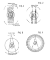
- the x-ray tube and detector are rotated through 1° and another linear scan is performed to acquire another view. This is repeated typically to acquire 180 views.
- FIG. 2 A second generation of devices developed to shorten the scanning times by gathering data more quickly is shown in FIG. 2 .
- a modified fan beam in which anywhere from three to 52 individual collimated x-ray beams and an equal number of detectors are used. Individual beams resemble the single beam of a first generation scanner. However, a collection of from three to 52 of these beams contiguous to one another allows multiple adjacent cores of tissue to be examined simultaneously. The configuration of these contiguous cores of tissue resembles a fan, with the thickness of the fan material determined by the collimation of the beam and in turn determining the slice thickness. Because of the angular difference of each beam relative to the others, several different angular views through the body slice are being examined simultaneously.
- third generation scanners therefore use a much wider fan beam.
- the angle of the beam may be wide enough to encompass most or all of an entire patient section without the need for a linear translation of the x-ray tube and detectors.
- the detectors now in the form of a large array, are rigidly aligned relative to the x-ray beam, and there are no translational motions at all.
- the tube and detector array are synchronously rotated about the patient through an angle of 180-360°.
- there is only one type of motion allowing a much faster scanning time to be achieved. After one rotation, a single tomographic section is obtained.
- Fourth generation scanners feature a wide fan beam similar to the third generation CT system as shown in FIG. 4 .
- the x-ray tube rotates through 360° without having to make any translational motion.
- the detectors are not aligned rigidly relative to the x-ray beam. In this system only the x-ray tube rotates. A large ring of detectors are fixed in an outer circle in the scanning plane. The necessity of rotating only the tube, but not the detectors, allows faster scan time.
- FBP filtered backprojection
- Three-dimensional CT or volume CT
- Each view is thus a 2D array of x-ray attenuation measurements and a complete scan produced by acquiring multiple views as the x-ray source and detector array are revolved around the subject results in a 3D array of attenuation measurements.
- the reason for this difficulty is that the simple relation between the Radon transform and the x-ray projection transform for the 2D case in not valid in the 3D cone beam case.
- the Radon transform is defined as an integral over a plane, not an integral along a straight line.
- the present invention is a method for reconstructing an image from fan beam attenuation measurements that does not rely on the Radon transformation method.
- a general method for reconstructing an image from fan beam projection views includes: calculating the derivative of each projection along the trajectory of the x-ray source; convolving the derivative data with a kernel function; back projecting the convolved data with a weight function; and add the back projected data to the image.
- a more specific application of this method to a third generation scanner having a circular x-ray source trajectory and either a flat or actuate detector array includes: filtering each acquired projection view by a first filter factor; backprojecting each resulting filtered view Q 1 ( ⁇ ) with a first weight; adding the backprojected data to the image; filtering each acquired projection view by a second filter factor; backprojecting each resulting filtered view Q 2 ( ⁇ ) with a second weight; and adding the backprojected data to this image.
- the image evolves as projection views are acquired and processed from a blurry and unrecognizable subject to a finished image.
- a general object of this invention is to accurately reconstruct an image from a scan using a fan beam source and a detector array. Accurate images may be reconstructed when the source travels in a circular path around the object to be imaged or when the path is not circular.
- Another object of the invention is to provide an image reconstruction method in which each acquired view is processed and added to an image. Rather than acquiring the entire raw data set and then reconstructing an image therefrom, the present invention enables each view to be processed as the scan is conducted. The image thus evolves as the scan is conducted.
- Another object of the invention is to reduce the number of views needed to satisfy data sufficiency conditions. To meet this condition it is only necessary that the x-ray source travel around the object being imaged such that any straight line through the object in the plane of the x-ray source motion will intersect the x-ray source path. This means that when smaller objects are being imaged, views over a smaller range of view angles need be acquired to satisfy this sufficiency condition. This translates to less radiation exposure and is particularly advantageous for pediatric imaging.
- FIGS. 1-4 are schematic representations of different CT system geometries
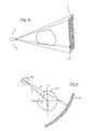
- FIG. 5 is a pictorial representation of a 3D, or volume, CT system
- FIG. 6 is a schematic representation of a third generation CT system with a coordinate system used to generally describe the invention.
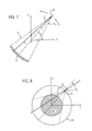
- FIG. 7 is a schematic representation of a third generation CT system with coordinate system used to describe the application of the invention to one preferred embodiment
- FIG. 8 is a schematic representation of the CT system of FIG. 7 with additional variables shown;
- FIG. 9 is a schematic representation of another third generation CT system with coordinate system used to describe the application of the invention to another preferred embodiment
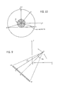
- FIG. 10 is a schematic representation of a CT system region of interest with coordinates and variables used to explain the minimum gantry movement required during a scan;
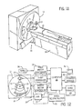
- FIG. 11 is a pictorial view of a CT system which employs the present invention.
- FIG. 12 is a block diagram of the CT system of FIG. 11 ;
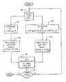
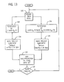
- FIG. 13 is a flow chart of the steps performed by the CT system of FIGS. 11 and 12 to practice a preferred embodiment of the invention
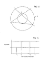
- FIG. 14 is a pictorial representation of the FOV of the CT system of FIG. 7 used to explain weighting.
- FIG. 15 is a graphic representation of the weighting used in the method of FIG. 13 .
- the present invention is a new method for reconstructing images from acquired divergent beam projections. This method will be described with respect to 2D fan-beam projections, but the approach is also applicable to 3D cone beam projections.
- G 2 ( ⁇ right arrow over (k) ⁇ , ⁇ right arrow over (y) ⁇ ) by taking a local Fourier transform for the vector ⁇ right arrow over (r) ⁇ in fan beam projections g( ⁇ right arrow over (r) ⁇ , ⁇ right arrow over (y) ⁇ ).
- the general inversion formula in Eq. (12) can be reformatted into a form in which the filtered back projection step is more apparent.
- G 2 ⁇ circumflex over (k) ⁇ , ⁇ right arrow over (y) ⁇ .
- n( ⁇ right arrow over (x) ⁇ , ⁇ circumflex over (k) ⁇ ) is the total number of redundant projections for Eq. (11).
- This modified general inversion formula takes the average of all redundant projections that satisfy Eq. (11).
- Equation (17) is not very convenient in practice because of the summation procedure it requires.
- the image evolves from a blurry, unrecognizable subject to a finished image.
- FIG. 7 a third generation scanner having an x-ray source 10 at a radius R emits a fan beam over angle ⁇ m which is received by an arc detector 12 .
- a third generation scanner having an x-ray source 10 at a radius R emits a fan beam over angle ⁇ m which is received by an arc detector 12 .
- ⁇ m which is received by an arc detector 12 .
- f ⁇ ( x ⁇ ) - 1 4 ⁇ ⁇ 2 ⁇ ⁇ ⁇ d t ⁇ w ⁇ ( x ⁇ , t ) ⁇ sgn ⁇ ( x - R ⁇ ⁇ cos ⁇ ⁇ t ) ⁇ x ⁇ - y ⁇ ⁇ ( t ) ⁇ ⁇ ⁇ ⁇ 0 ⁇ m ⁇ ⁇ d ⁇ ⁇ 1 cos ( ⁇ ⁇ - t - ⁇ + ⁇ m / 2 ⁇ ( ⁇ ⁇ t - ⁇ ⁇ ⁇ ) ⁇ g m ⁇ ( ⁇ , t ) .
- Equations (42) and (41) are the optimal formulas for an accurate reconstruction of the ROI from the fan beam projections produced by the third generation scanner of FIG. 7 , provided the x-ray source trajectory revolves around the ROI to satisfy the data sufficiency condition Eq. (11).
- Eq. (42) the integral over t ⁇ is implied.
- this new formula allows us to reconstruct the image sequentially.
- STEP 2 For each view, filter the measured data by a filter 1 sin ⁇ ( ⁇ - ⁇ m / 2 ) (the result is called Q 1 ( ⁇ )) and filter the modified projections by the other filter 1 sin 2 ⁇ ( ⁇ - ⁇ m / 2 ) (the result is called Q 2 ( ⁇ )).
- STEP 3 For each view, backproject the filtered data Q 1 ( ⁇ ) with a weight w ′ ⁇ ( ⁇ x -> , t ⁇ ) ⁇ x -> - y -> ⁇ ( t ) ⁇ and backproject the filtered data Q 2 ( ⁇ ) with a weight R ⁇ ⁇ w ⁇ ( ⁇ x -> , t ⁇ ) ⁇ x -> - y -> ⁇ ( t ) ⁇ 2 .
- STEP 4 Add up all the contributions from all the different view angles t. In this manner an image is produced immediately by the above filtered backprojection.
- the image evolves as successive views g( ⁇ ,t) are acquired and processed to change from a blurry, unrecognizable subject to a finished image.
- Eq. (24) Using the image reconstruction method indicated above in Eq. (24) one ends up with a general filtered backprojection scheme. It is general in the sense that it yields a mathematically exact image reconstruction for any differentiable planar x-ray source trajectory and any detector configuration.
- the image reconstruction methods indicated by Eqs. (42) and (44) produce mathematically exact images for the clinically useful scanner geometries having a circular x-ray source trajectory with a third generation arc detector and collinear detector respectively.
- the method expressed by Eqs. (42) and (44) are valid for a wide range of weighting functions, they do not require taking the derivative of acquired attenuation data, and the image reconstruction can be performed sequentially in real time.
- each view can be processed after it is acquired to form an image and the image is continuously improved as more views are acquired and processed.
- two extra terms in these reconstruction equations also enable the scan path to be shortened without truncating the data set needed to produce an artifact free image.
- ROI region of interest
- the ROI may be the whole function support region ⁇ of the scanner, or it may be a smaller part of the function support region ⁇ .
- the ROI 18 consists of a concentric disc region with radius r ⁇ R, then the data sufficiency condition Eq. (11) requires that the x-ray source trajectory is the bigger arc (AMB) of the circle. It is easy to see that the corresponding angle for this arc is ⁇ +2 arcsin (r/R).
- Two prescriptions for the weighting function are preferred. It is important to understand that this invention is the first method to explicitly introduce image pixel ⁇ right arrow over (x) ⁇ into a weighting function. In the first method, a ray-driven weighting function is used in which the weighting function does not depend on the image pixels. In other words, there is no ⁇ right arrow over (x) ⁇ dependence. In the second method, a pixel-driven weighting function is used in which the choice of the weighting function strongly depends on the pixels.
- the weighting scheme is to assign weight 1 ⁇ 2 for the first and last pieces of the orbit and assign weight 1 for the second piece as shown in FIG. 15 .
- the second terms in equations (42) and (44) do not play any role and thus the computational load can be reduced by just calculating the first and the last terms.
- a computed tomography (CT) imaging system 10 includes a gantry 12 representative of a “third generation” CT scanner.
- Gantry 12 has an x-ray source 13 that projects a fan beam of x-rays 14 toward a detector array 16 on the opposite side of the gantry.
- the detector array 16 is formed by a number of detector elements 18 which together sense the projected x-rays that pass through a medical patient 15 .
- Each detector element 18 produces an electrical signal that represents the intensity of an impinging x-ray beam and hence the attenuation of the beam as it passes through the patient.
- the gantry 12 and the components mounted thereon rotate about a center of rotation 19 located within the patient 15 .
- the rotation of the gantry and the operation of the x-ray source 13 are governed by a control mechanism 20 of the CT system.
- the control mechanism 20 includes an x-ray controller 22 that provides power and timing signals to the x-ray source 13 and a gantry motor controller 23 that controls the rotational speed and position of the gantry 12 .
- a data acquisition system (DAS) 24 in the control mechanism 20 samples analog data from detector elements 18 and converts the data to digital signals for subsequent processing.
- An image reconstructor 25 receives sampled and digitized x-ray data from the DAS 24 and performs high speed image reconstruction according to the method of the present invention. The reconstructed image is applied as an input to a computer 26 which stores the image in a mass storage device 29 .
- DAS data acquisition system
- the computer 26 also receives commands and scanning parameters from an operator via console 30 that has a keyboard.
- An associated cathode ray tube display 32 allows the operator to observe the reconstructed image and other data from the computer 26 .
- the operator supplied commands and parameters are used by the computer 26 to provide control signals and information to the DAS 24 , the x-ray controller 22 and the gantry motor controller 23 .
- computer 26 operates a table motor controller 34 which controls a motorized table 36 to position the patient 15 in the gantry 12 .
- the CT imaging system is operated to acquire views of attenuation data g( ⁇ ,t) at a series of gantry angles ⁇ as the x-ray source 13 is moved to a series of locations t on a circular path.
- an arcuate shaped detector array 16 is employed and the reconstruction method according to the above equation (44) is employed.
- each acquired view g( ⁇ ,t) is processed in near real time and the resulting backprojecting image data is added to an image data set which can be displayed even as the scan is being performed.
- each view is acquired as indicated at process block 100 and processed in two parallel paths.
- the attenuation data g( ⁇ ,t) is filtered by multiplying by a first filter 1/sin( ⁇ m /2) as indicated by process block 102 .
- the resulting filtered data set Q 1 ( ⁇ ) is then backprojected as indicated at process block 104 with a weighting factor of w′( ⁇ right arrow over (x) ⁇ , ⁇ right arrow over (y) ⁇ )/
- the same attenuation data g( ⁇ ,t) is processed in a second path in which it is first filtered as indicated by process block 106 with cos( ⁇ m /2)/[sin( ⁇ m /2)*sin( ⁇ m /2)].
- the resulting filtered data set is then backprojected as indicated at process block 108 with a weight RW( ⁇ right arrow over (x) ⁇ ,t)/
- the resulting image data from the two, parallel backprojections 104 and 108 are added to an image data set as indicated at process block 110 .
- the system loops back at decision block 112 until sufficient views have been acquired to satisfy the data sufficiency condition of Eq. (11).
- Equation (24) The generalized form of the reconstruction method as expressed in Eq. (24) may be employed when the x-ray source travels a non-circular path. It is contemplated that this reconstruction method may be used when the x-ray source does not follow a perfect circular path due to manufacturing tolerances or wear. In such case, the exact path is measured during a calibration procedure and Equation (24) is implemented in the reconstruction process using the exact, measured source path.
Landscapes
- Physics & Mathematics (AREA)
- General Physics & Mathematics (AREA)
- Engineering & Computer Science (AREA)
- Theoretical Computer Science (AREA)
- Apparatus For Radiation Diagnosis (AREA)
- Image Processing (AREA)
Priority Applications (4)
| Application Number | Priority Date | Filing Date | Title |
|---|---|---|---|
| US10/651,673 US6990167B2 (en) | 2003-08-29 | 2003-08-29 | Image reconstruction method for divergent beam scanner |
| PCT/US2004/027679 WO2005076775A2 (fr) | 2003-08-29 | 2004-08-26 | Procede de reconstruction d'images pour dispositif de balayage a faisceaux divergents |
| JP2006524835A JP2007512034A (ja) | 2003-08-29 | 2004-08-26 | 発散ビームスキャナのための画像再構成方法 |
| EP04821343A EP1749281A2 (fr) | 2003-08-29 | 2004-08-26 | Procede de reconstruction d'images pour dispositif de balayage a faisceaux divergents |
Applications Claiming Priority (1)
| Application Number | Priority Date | Filing Date | Title |
|---|---|---|---|
| US10/651,673 US6990167B2 (en) | 2003-08-29 | 2003-08-29 | Image reconstruction method for divergent beam scanner |
Publications (2)
| Publication Number | Publication Date |
|---|---|
| US20050047542A1 US20050047542A1 (en) | 2005-03-03 |
| US6990167B2 true US6990167B2 (en) | 2006-01-24 |
Family
ID=34217452
Family Applications (1)
| Application Number | Title | Priority Date | Filing Date |
|---|---|---|---|
| US10/651,673 Expired - Lifetime US6990167B2 (en) | 2003-08-29 | 2003-08-29 | Image reconstruction method for divergent beam scanner |
Country Status (4)
| Country | Link |
|---|---|
| US (1) | US6990167B2 (fr) |
| EP (1) | EP1749281A2 (fr) |
| JP (1) | JP2007512034A (fr) |
| WO (1) | WO2005076775A2 (fr) |
Cited By (26)
| Publication number | Priority date | Publication date | Assignee | Title |
|---|---|---|---|---|
| US20060067457A1 (en) * | 2004-09-29 | 2006-03-30 | Kabushiki Kaisha Toshiba | Image reconstruction method using hilbert transform |
| US20070041500A1 (en) * | 2005-07-23 | 2007-02-22 | Olivera Gustavo H | Radiation therapy imaging and delivery utilizing coordinated motion of gantry and couch |
| US20070041495A1 (en) * | 2005-07-22 | 2007-02-22 | Olivera Gustavo H | Method of and system for predicting dose delivery |
| US20070041494A1 (en) * | 2005-07-22 | 2007-02-22 | Ruchala Kenneth J | Method and system for evaluating delivered dose |
| US20070041499A1 (en) * | 2005-07-22 | 2007-02-22 | Weiguo Lu | Method and system for evaluating quality assurance criteria in delivery of a treatment plan |
| US20070043286A1 (en) * | 2005-07-22 | 2007-02-22 | Weiguo Lu | Method and system for adapting a radiation therapy treatment plan based on a biological model |
| US20070041497A1 (en) * | 2005-07-22 | 2007-02-22 | Eric Schnarr | Method and system for processing data relating to a radiation therapy treatment plan |
| US20070104316A1 (en) * | 2005-07-22 | 2007-05-10 | Ruchala Kenneth J | System and method of recommending a location for radiation therapy treatment |
| US20070189591A1 (en) * | 2005-07-22 | 2007-08-16 | Weiguo Lu | Method of placing constraints on a deformation map and system for implementing same |
| US20070195929A1 (en) * | 2005-07-22 | 2007-08-23 | Ruchala Kenneth J | System and method of evaluating dose delivered by a radiation therapy system |
| US20070201613A1 (en) * | 2005-07-22 | 2007-08-30 | Weiguo Lu | System and method of detecting a breathing phase of a patient receiving radiation therapy |
| US20070268994A1 (en) * | 2006-05-02 | 2007-11-22 | Guang-Hong Chen | X- Ray System For Use in Image Guided Procedures |
| US20090219289A1 (en) * | 2008-02-28 | 2009-09-03 | International Business Machines Corporation | Fast three-dimensional visualization of object volumes without image reconstruction by direct display of acquired sensor data |
| US7609809B2 (en) | 2005-07-22 | 2009-10-27 | Tomo Therapy Incorporated | System and method of generating contour structures using a dose volume histogram |
| US20100286928A1 (en) * | 2009-05-08 | 2010-11-11 | Frank Dennerlein | Method and device for determining images from x-ray projections |
| US20100329514A1 (en) * | 2008-02-20 | 2010-12-30 | Uwe Mundry | Tomographic imaging motion scan quality rating |
| CN102028490A (zh) * | 2009-09-24 | 2011-04-27 | 西门子公司 | 从在遍历轨迹时拍摄的x射线投影确定图像的方法和设备 |
| US7957507B2 (en) | 2005-02-28 | 2011-06-07 | Cadman Patrick F | Method and apparatus for modulating a radiation beam |
| US8232535B2 (en) | 2005-05-10 | 2012-07-31 | Tomotherapy Incorporated | System and method of treating a patient with radiation therapy |
| US8442287B2 (en) | 2005-07-22 | 2013-05-14 | Tomotherapy Incorporated | Method and system for evaluating quality assurance criteria in delivery of a treatment plan |
| US8615121B2 (en) | 2011-05-31 | 2013-12-24 | General Electric Company | Reconstruction of projection data to generate tomographic images having improved frequency characteristics |
| US8767917B2 (en) | 2005-07-22 | 2014-07-01 | Tomotherapy Incorpoated | System and method of delivering radiation therapy to a moving region of interest |
| US8805037B2 (en) | 2011-05-31 | 2014-08-12 | General Electric Company | Method and system for reconstruction of tomographic images |
| US20140254905A1 (en) * | 2013-03-11 | 2014-09-11 | General Electric Company | Computed tomography image reconstruction |
| US8861829B2 (en) | 2011-09-30 | 2014-10-14 | General Electric Company | Method and system for reconstruction of tomographic images |
| US9443633B2 (en) | 2013-02-26 | 2016-09-13 | Accuray Incorporated | Electromagnetically actuated multi-leaf collimator |
Families Citing this family (6)
| Publication number | Priority date | Publication date | Assignee | Title |
|---|---|---|---|---|
| US7583777B2 (en) * | 2004-07-21 | 2009-09-01 | General Electric Company | Method and apparatus for 3D reconstruction of images |
| WO2006073584A2 (fr) * | 2004-11-24 | 2006-07-13 | Wisconsin Alumni Research Foundation | Procede de reconstruction d'image par retroprojection filtree de faisceau de cone pour petites trajectoires |
| BRPI0715216A2 (pt) * | 2006-08-03 | 2013-06-18 | The Regents Of The University Of California | mÉtodo para reconstruir uma representaÇço da imagem de um objeto a partir de suas projeÇÕes e para tratar imagens tomogrÁficas, e, produto de programa de computador |
| DE102007025678A1 (de) * | 2007-06-01 | 2008-12-04 | Rwth Aachen | Verfahren zur Bildverarbeitung und Bildverarbeitungseinrichtung |
| US7869566B2 (en) * | 2007-06-29 | 2011-01-11 | Morpho Detection, Inc. | Integrated multi-sensor systems for and methods of explosives detection |
| CN110428478B (zh) * | 2019-07-15 | 2021-09-24 | 清华大学 | 交替光源扇束x射线ct采样方法及装置 |
Citations (11)
| Publication number | Priority date | Publication date | Assignee | Title |
|---|---|---|---|---|
| US5257183A (en) | 1990-12-21 | 1993-10-26 | General Electric Company | Method and apparatus for converting cone beam X-ray projection data to planar integral and reconstructing a three-dimensional computerized tomography (CT) image of an object |
| US5270926A (en) | 1990-12-21 | 1993-12-14 | General Electric Company | Method and apparatus for reconstructing a three-dimensional computerized tomography (CT) image of an object from incomplete cone beam projection data |
| US5400255A (en) | 1994-02-14 | 1995-03-21 | General Electric Company | Reconstruction of images from cone beam data |
| US5625660A (en) | 1995-06-30 | 1997-04-29 | Picker International, Inc. | Image reconstruction from helical partial cone-beam data |
| US5881123A (en) * | 1998-03-31 | 1999-03-09 | Siemens Corporate Research, Inc. | Simplified cone beam image reconstruction using 3D backprojection |
| US6097784A (en) | 1998-09-30 | 2000-08-01 | Picker International, Inc. | 3D image reconstruction for helical partial cone beam data |
| US6104775A (en) | 1998-10-29 | 2000-08-15 | Picker International, Inc. | 3D image reconstruction for helical partial cone beam scanners using wedge beam transform |
| US6219441B1 (en) | 1993-06-22 | 2001-04-17 | General Electric Company | Reconstruction of images from three-dimensional cone beam data |
| US6292525B1 (en) * | 1999-09-30 | 2001-09-18 | Siemens Corporate Research, Inc. | Use of Hilbert transforms to simplify image reconstruction in a spiral scan cone beam CT imaging system |
| US6504892B1 (en) * | 2000-10-13 | 2003-01-07 | University Of Rochester | System and method for cone beam volume computed tomography using circle-plus-multiple-arc orbit |
| US20030097063A1 (en) * | 2001-11-21 | 2003-05-22 | Wang Sharon X. | High speed Z-smoothing method and apparatus for CT imaging system |
Family Cites Families (9)
| Publication number | Priority date | Publication date | Assignee | Title |
|---|---|---|---|---|
| US4149247A (en) * | 1975-12-23 | 1979-04-10 | Varian Associates, Inc. | Tomographic apparatus and method for reconstructing planar slices from non-absorbed and non-scattered radiation |
| US5115394A (en) * | 1983-11-25 | 1992-05-19 | Technicare Corporation | Dual energy computerized tomography system |
| US5396418A (en) * | 1988-10-20 | 1995-03-07 | Picker International, Inc. | Four dimensional spiral volume imaging using fast retrace |
| US5720926A (en) * | 1995-11-01 | 1998-02-24 | Environair S.I.P.A. Inc. | Apparatus for removing a contaminant from a gas |
| US5926521A (en) * | 1998-03-31 | 1999-07-20 | Siemens Corporate Research, Inc. | Exact region of interest cone beam imaging using 3D backprojection |
| JP2000178079A (ja) * | 1998-12-18 | 2000-06-27 | Kyocera Corp | ロウ材 |
| US6459754B1 (en) * | 1999-10-27 | 2002-10-01 | Ge Medical Systems Global Technology Company, Llc | Methods and apparatus for cone beam multislice CT correction |
| JP4078846B2 (ja) * | 2001-03-13 | 2008-04-23 | 株式会社島津製作所 | 断層撮影装置 |
| US6574299B1 (en) * | 2001-08-16 | 2003-06-03 | University Of Central Florida | Exact filtered back projection (FBP) algorithm for spiral computer tomography |
-
2003
- 2003-08-29 US US10/651,673 patent/US6990167B2/en not_active Expired - Lifetime
-
2004
- 2004-08-26 JP JP2006524835A patent/JP2007512034A/ja active Pending
- 2004-08-26 WO PCT/US2004/027679 patent/WO2005076775A2/fr not_active Ceased
- 2004-08-26 EP EP04821343A patent/EP1749281A2/fr not_active Withdrawn
Patent Citations (11)
| Publication number | Priority date | Publication date | Assignee | Title |
|---|---|---|---|---|
| US5257183A (en) | 1990-12-21 | 1993-10-26 | General Electric Company | Method and apparatus for converting cone beam X-ray projection data to planar integral and reconstructing a three-dimensional computerized tomography (CT) image of an object |
| US5270926A (en) | 1990-12-21 | 1993-12-14 | General Electric Company | Method and apparatus for reconstructing a three-dimensional computerized tomography (CT) image of an object from incomplete cone beam projection data |
| US6219441B1 (en) | 1993-06-22 | 2001-04-17 | General Electric Company | Reconstruction of images from three-dimensional cone beam data |
| US5400255A (en) | 1994-02-14 | 1995-03-21 | General Electric Company | Reconstruction of images from cone beam data |
| US5625660A (en) | 1995-06-30 | 1997-04-29 | Picker International, Inc. | Image reconstruction from helical partial cone-beam data |
| US5881123A (en) * | 1998-03-31 | 1999-03-09 | Siemens Corporate Research, Inc. | Simplified cone beam image reconstruction using 3D backprojection |
| US6097784A (en) | 1998-09-30 | 2000-08-01 | Picker International, Inc. | 3D image reconstruction for helical partial cone beam data |
| US6104775A (en) | 1998-10-29 | 2000-08-15 | Picker International, Inc. | 3D image reconstruction for helical partial cone beam scanners using wedge beam transform |
| US6292525B1 (en) * | 1999-09-30 | 2001-09-18 | Siemens Corporate Research, Inc. | Use of Hilbert transforms to simplify image reconstruction in a spiral scan cone beam CT imaging system |
| US6504892B1 (en) * | 2000-10-13 | 2003-01-07 | University Of Rochester | System and method for cone beam volume computed tomography using circle-plus-multiple-arc orbit |
| US20030097063A1 (en) * | 2001-11-21 | 2003-05-22 | Wang Sharon X. | High speed Z-smoothing method and apparatus for CT imaging system |
Non-Patent Citations (1)
| Title |
|---|
| Image Reconstruction From Fan-Beam Projections On Less Than A Short Scan, Phys. Med. Biol. 47 (2002) 2525-2546; Noo, et al. |
Cited By (40)
| Publication number | Priority date | Publication date | Assignee | Title |
|---|---|---|---|---|
| US7424088B2 (en) * | 2004-09-29 | 2008-09-09 | Kabushiki Kaisha Toshiba | Image reconstruction method using Hilbert transform |
| US20060067457A1 (en) * | 2004-09-29 | 2006-03-30 | Kabushiki Kaisha Toshiba | Image reconstruction method using hilbert transform |
| US7957507B2 (en) | 2005-02-28 | 2011-06-07 | Cadman Patrick F | Method and apparatus for modulating a radiation beam |
| US8232535B2 (en) | 2005-05-10 | 2012-07-31 | Tomotherapy Incorporated | System and method of treating a patient with radiation therapy |
| US7773788B2 (en) | 2005-07-22 | 2010-08-10 | Tomotherapy Incorporated | Method and system for evaluating quality assurance criteria in delivery of a treatment plan |
| US20070043286A1 (en) * | 2005-07-22 | 2007-02-22 | Weiguo Lu | Method and system for adapting a radiation therapy treatment plan based on a biological model |
| US20070041497A1 (en) * | 2005-07-22 | 2007-02-22 | Eric Schnarr | Method and system for processing data relating to a radiation therapy treatment plan |
| US20070104316A1 (en) * | 2005-07-22 | 2007-05-10 | Ruchala Kenneth J | System and method of recommending a location for radiation therapy treatment |
| US20070189591A1 (en) * | 2005-07-22 | 2007-08-16 | Weiguo Lu | Method of placing constraints on a deformation map and system for implementing same |
| US20070195929A1 (en) * | 2005-07-22 | 2007-08-23 | Ruchala Kenneth J | System and method of evaluating dose delivered by a radiation therapy system |
| US20070201613A1 (en) * | 2005-07-22 | 2007-08-30 | Weiguo Lu | System and method of detecting a breathing phase of a patient receiving radiation therapy |
| US7839972B2 (en) | 2005-07-22 | 2010-11-23 | Tomotherapy Incorporated | System and method of evaluating dose delivered by a radiation therapy system |
| US20070041499A1 (en) * | 2005-07-22 | 2007-02-22 | Weiguo Lu | Method and system for evaluating quality assurance criteria in delivery of a treatment plan |
| US7567694B2 (en) | 2005-07-22 | 2009-07-28 | Tomotherapy Incorporated | Method of placing constraints on a deformation map and system for implementing same |
| US7574251B2 (en) | 2005-07-22 | 2009-08-11 | Tomotherapy Incorporated | Method and system for adapting a radiation therapy treatment plan based on a biological model |
| US8442287B2 (en) | 2005-07-22 | 2013-05-14 | Tomotherapy Incorporated | Method and system for evaluating quality assurance criteria in delivery of a treatment plan |
| US7609809B2 (en) | 2005-07-22 | 2009-10-27 | Tomo Therapy Incorporated | System and method of generating contour structures using a dose volume histogram |
| US7639853B2 (en) | 2005-07-22 | 2009-12-29 | Tomotherapy Incorporated | Method of and system for predicting dose delivery |
| US7639854B2 (en) | 2005-07-22 | 2009-12-29 | Tomotherapy Incorporated | Method and system for processing data relating to a radiation therapy treatment plan |
| US7643661B2 (en) | 2005-07-22 | 2010-01-05 | Tomo Therapy Incorporated | Method and system for evaluating delivered dose |
| US8229068B2 (en) | 2005-07-22 | 2012-07-24 | Tomotherapy Incorporated | System and method of detecting a breathing phase of a patient receiving radiation therapy |
| US20070041494A1 (en) * | 2005-07-22 | 2007-02-22 | Ruchala Kenneth J | Method and system for evaluating delivered dose |
| US8767917B2 (en) | 2005-07-22 | 2014-07-01 | Tomotherapy Incorpoated | System and method of delivering radiation therapy to a moving region of interest |
| US20070041495A1 (en) * | 2005-07-22 | 2007-02-22 | Olivera Gustavo H | Method of and system for predicting dose delivery |
| US9731148B2 (en) | 2005-07-23 | 2017-08-15 | Tomotherapy Incorporated | Radiation therapy imaging and delivery utilizing coordinated motion of gantry and couch |
| US20070041500A1 (en) * | 2005-07-23 | 2007-02-22 | Olivera Gustavo H | Radiation therapy imaging and delivery utilizing coordinated motion of gantry and couch |
| US20070268994A1 (en) * | 2006-05-02 | 2007-11-22 | Guang-Hong Chen | X- Ray System For Use in Image Guided Procedures |
| US20100329514A1 (en) * | 2008-02-20 | 2010-12-30 | Uwe Mundry | Tomographic imaging motion scan quality rating |
| US20090219289A1 (en) * | 2008-02-28 | 2009-09-03 | International Business Machines Corporation | Fast three-dimensional visualization of object volumes without image reconstruction by direct display of acquired sensor data |
| US9858716B2 (en) * | 2008-02-28 | 2018-01-02 | International Business Machines Corporation | Fast three-dimensional visualization of object volumes without image reconstruction by direct display of acquired sensor data |
| US8619944B2 (en) | 2009-05-08 | 2013-12-31 | Siemens Aktiengesellschaft | Method and device for determining images from X-ray projections |
| US20100286928A1 (en) * | 2009-05-08 | 2010-11-11 | Frank Dennerlein | Method and device for determining images from x-ray projections |
| CN102028490A (zh) * | 2009-09-24 | 2011-04-27 | 西门子公司 | 从在遍历轨迹时拍摄的x射线投影确定图像的方法和设备 |
| CN102028490B (zh) * | 2009-09-24 | 2014-06-18 | 西门子公司 | 从在遍历轨迹时拍摄的x射线投影确定图像的方法和设备 |
| US8615121B2 (en) | 2011-05-31 | 2013-12-24 | General Electric Company | Reconstruction of projection data to generate tomographic images having improved frequency characteristics |
| US8805037B2 (en) | 2011-05-31 | 2014-08-12 | General Electric Company | Method and system for reconstruction of tomographic images |
| US8861829B2 (en) | 2011-09-30 | 2014-10-14 | General Electric Company | Method and system for reconstruction of tomographic images |
| US9443633B2 (en) | 2013-02-26 | 2016-09-13 | Accuray Incorporated | Electromagnetically actuated multi-leaf collimator |
| US20140254905A1 (en) * | 2013-03-11 | 2014-09-11 | General Electric Company | Computed tomography image reconstruction |
| US8948337B2 (en) * | 2013-03-11 | 2015-02-03 | General Electric Company | Computed tomography image reconstruction |
Also Published As
| Publication number | Publication date |
|---|---|
| JP2007512034A (ja) | 2007-05-17 |
| EP1749281A2 (fr) | 2007-02-07 |
| US20050047542A1 (en) | 2005-03-03 |
| WO2005076775A2 (fr) | 2005-08-25 |
| WO2005076775A3 (fr) | 2007-01-18 |
Similar Documents
| Publication | Publication Date | Title |
|---|---|---|
| US6990167B2 (en) | Image reconstruction method for divergent beam scanner | |
| JP5019193B2 (ja) | スキャン対象に関するct画像内の再構成点における画像データ値を決定する再構成方法及びx線コンピュータ断層撮影装置 | |
| US7203272B2 (en) | Cone-beam filtered backprojection image reconstruction method for short trajectories | |
| EP0997849B1 (fr) | Réconstruction d'images | |
| US5400255A (en) | Reconstruction of images from cone beam data | |
| US5257183A (en) | Method and apparatus for converting cone beam X-ray projection data to planar integral and reconstructing a three-dimensional computerized tomography (CT) image of an object | |
| US7251307B2 (en) | Fan-beam and cone-beam image reconstruction using filtered backprojection of differentiated projection data | |
| EP1096426B1 (fr) | Procédé et appareil pour la correction de la tomographie multicouche à faisceau conique | |
| US6411670B1 (en) | Data rebinning to increase resolution in CT image reconstruction | |
| US6219441B1 (en) | Reconstruction of images from three-dimensional cone beam data | |
| US6574297B2 (en) | System and method for image reconstruction in a cone beam imaging system | |
| JP4553894B2 (ja) | 正確な再構成を伴うヘリカルコーンビームコンピュータトモグラフィのためのシステム及び方法 | |
| EP1644897B1 (fr) | Procede de reconstruction d'images tomographiques par transformee de fourier pour des donnees de faisceau en eventail | |
| US7050528B2 (en) | Correction of CT images for truncated or incomplete projections | |
| EP0991022B1 (fr) | Procédé et dispositif de reconstruction d'image | |
| EP0991021A2 (fr) | Reconstitution d'images des données de faisceaux coniques | |
| EP0989521B1 (fr) | Réconstruction d'image fluoroscopique | |
| US20060203955A1 (en) | Computer tomography method for a periodically moving object | |
| US6999550B2 (en) | Method and apparatus for obtaining data for reconstructing images of an object | |
| US7173996B2 (en) | Methods and apparatus for 3D reconstruction in helical cone beam volumetric CT | |
| WO2005107598A1 (fr) | Tomographie par ordinateur a faisceau conique par balayage circulaire et lineaire efficace | |
| Ramamurthi et al. | Exact 3D cone-beam reconstruction from two short-scans using a C-arm imaging system |
Legal Events
| Date | Code | Title | Description |
|---|---|---|---|
| AS | Assignment |
Owner name: WISCONSIN ALUMNI RESEARCH FOUNDATION, WISCONSIN Free format text: ASSIGNMENT OF ASSIGNORS INTEREST;ASSIGNOR:CHEN, GUANG-HONG;REEL/FRAME:014741/0773 Effective date: 20030826 |
|
| STCF | Information on status: patent grant |
Free format text: PATENTED CASE |
|
| FEPP | Fee payment procedure |
Free format text: PAT HOLDER CLAIMS SMALL ENTITY STATUS, ENTITY STATUS SET TO SMALL (ORIGINAL EVENT CODE: LTOS); ENTITY STATUS OF PATENT OWNER: SMALL ENTITY |
|
| FPAY | Fee payment |
Year of fee payment: 4 |
|
| FPAY | Fee payment |
Year of fee payment: 8 |
|
| FPAY | Fee payment |
Year of fee payment: 12 |
|
| CC | Certificate of correction |