US7002741B2 - Image transmission system for endoscopes and method of producing a rod lens - Google Patents
Image transmission system for endoscopes and method of producing a rod lens Download PDFInfo
- Publication number
- US7002741B2 US7002741B2 US09/949,608 US94960801A US7002741B2 US 7002741 B2 US7002741 B2 US 7002741B2 US 94960801 A US94960801 A US 94960801A US 7002741 B2 US7002741 B2 US 7002741B2
- Authority
- US
- United States
- Prior art keywords
- lens
- lenses
- designates
- rod
- convex
- Prior art date
- Legal status (The legal status is an assumption and is not a legal conclusion. Google has not performed a legal analysis and makes no representation as to the accuracy of the status listed.)
- Expired - Lifetime, expires
Links
- 230000005540 biological transmission Effects 0.000 title claims abstract description 84
- 238000000034 method Methods 0.000 title claims abstract description 17
- 239000011521 glass Substances 0.000 claims description 18
- 238000004519 manufacturing process Methods 0.000 claims description 8
- 230000005499 meniscus Effects 0.000 claims description 7
- 230000009977 dual effect Effects 0.000 claims 3
- 238000010276 construction Methods 0.000 abstract description 2
- 230000015572 biosynthetic process Effects 0.000 description 11
- 230000003287 optical effect Effects 0.000 description 3
- 201000009310 astigmatism Diseases 0.000 description 2
- 238000005498 polishing Methods 0.000 description 2
- 239000004568 cement Substances 0.000 description 1
- 230000007812 deficiency Effects 0.000 description 1
- 230000000694 effects Effects 0.000 description 1
- 239000000047 product Substances 0.000 description 1
- 238000002310 reflectometry Methods 0.000 description 1
- 239000013589 supplement Substances 0.000 description 1
Images


Classifications
-
- G—PHYSICS
- G02—OPTICS
- G02B—OPTICAL ELEMENTS, SYSTEMS OR APPARATUS
- G02B23/00—Telescopes, e.g. binoculars; Periscopes; Instruments for viewing the inside of hollow bodies; Viewfinders; Optical aiming or sighting devices
- G02B23/24—Instruments or systems for viewing the inside of hollow bodies, e.g. fibrescopes
- G02B23/2407—Optical details
- G02B23/2446—Optical details of the image relay
-
- G—PHYSICS
- G02—OPTICS
- G02B—OPTICAL ELEMENTS, SYSTEMS OR APPARATUS
- G02B13/00—Optical objectives specially designed for the purposes specified below
- G02B13/0095—Relay lenses or rod lenses
Definitions
- the invention relates to an image transmission system for endoscopes and similar viewing tubes with at least one rod lens and with at least one additional lens system.
- the invention relates to a process for producing a rod lens for an image transmission system as well as an endoscope equipped with a similar image transmission system.
- Image transmission systems of this kind are used in particular for endoscopes but also for other viewing tubes such as technoscopes, cystoscopes, periscopes, and the like.
- Endoscopes consist of an eyepiece part, which contains the eyepiece, as well as an elongated shaft in which additional optical components are positioned.
- These other optical components consist of the lens mounted on the front (distal) end of the endoscope and image transmission or relay lens systems. The lens receives the scene to be observed and produces an interim image in an initial inter-image plane. This interim image is again pictured by an image transmission or relay lens system and carried to the next inter-image plane, from where an additional image transmission or relay lens system assumes the task of forwarding to the next inter-image plane, until the image reaches the eyepiece.
- Every image transmission system consists of two biconvex rod-shaped lenses and at least two additional meniscus lenses.
- the combination of rod-shaped biconvex lenses with meniscus lenses permits, first of all, the achievement of great image brightness, and second, a sufficiently good compensation for image errors such as astigmatisms and image field curvature that disturb image transmission systems.
- An additional image transmission system of this type is familiar, for instance, from EP-B1-0 310 640.
- the rod lenses consist of convex/concave lenses, whose concave surfaces are turned toward the center plane and which are each cemented together with one additional lens system.
- the additional lens systems are biconvex single lenses, where the concave surfaces of the rod lenses are each cemented together with one of the convex surfaces of the other lens systems.
- each relay lens system consists of two identically built lens systems with one middle biconvex lens and two convex/concave lenses cemented together with this middle lens.
- the biconvex middle lens in this familiar lens system can be produced from a glass sphere out of which a cylindrical rod with two convex terminal surfaces is produced through appropriate processes such as for instance polishing. Because of the many spherical cementing surfaces between the middle lenses and the convex/concave lenses connected with them, this familiar lens system too can only be produced at considerable expense, since the surfaces to be joined together must be processed with great accuracy.
- the invention is based on the task of producing an image transmission system of the kind mentioned at the outset, which can be produced with the simplest possible rod lenses and which ensures a good correction of the image field curvature.
- the invention is based on the task of developing an economically feasible process for producing a rod lens for an image transmission system.
- the product solution of this task is characterized in that at least one rod lens is formed as a plano-convex lens, whose length corresponds to the curvature radius of its convex terminal surface.
- Rod lenses formed in this manner can be produced, for instance, at reasonable cost from one-piece biconvex lenses whose length is twice as great as the curvature radius of the two convex terminal surfaces, which are severed in order to produce two plano-convex rod lenses along the center plane.
- the plane terminal surface of at least one plano-convex rod lens forms the beginning and/or end of the respective image transmission system.
- the rod lenses of two sequentially arranged image transmission systems are cemented together at their plane terminal surfaces. Through this direct joining of two rod lenses, it is possible to eliminate an additional glass-air surface from the image transmission system.
- a considerable cost advantage and a clear simplification of the production process can be achieved, according to the invention, because two sequentially arranged rod lenses are formed as one-piece biconvex rod lenses, whose length is twice as large as the curvature radius of the two convex terminal surfaces, where one half of the biconvex rod lens is subordinated to the directly adjoining image transmission system.
- This type of formation of two rod lenses as one-piece biconvex lens is possibly without any substantive changes to the image transmission system because the plane terminal surfaces of the rod lenses produce no optically relevant effect and can be given up for the sake of a simply and economically produced one-piece biconvex rod lens.
- this system is also very well adapted to the correction of image field curvature, especially in the tangential direction.
- the minimum of one additional lens system should be positioned symmetrically between two rod lenses with their convex terminal surfaces turned toward one another.
- the minimum of one additional lens system in accordance with the invention, consists of at least three lenses, whereby this lens system for best advantage should be constructed symmetrically and the refractive power of the two outer lenses has the opposite mathematical sign to that of the minimum of one middle lens.
- the additional lens system is formed as a threesome consisting of three lenses cemented together.
- the additional lens system should be formed as two pairs, each consisting of two lenses cemented together. In this manner, an air space can be ensured between the two pairs.
- the use of the two pairs has two additional glass-air surfaces and thus a loss of reflectivity of light energy, but this formation of the image transmission system using the rod lens, as proposed by the invention, is cost effective and simple to produce and permits a very good correction of image field curvature.
- the shape of the middle lens (in the threesome) or of the middle lenses (in the pairs) depends on the type of glass chosen.
- n m ⁇ n a the outer lenses of the additional lens system are formed as convex/concave meniscus lenses and the one (threesome) or two (pairs) middle lens(es) are formed as biconvex lenses, where n m is the refractive index of the middle lens(es) and n a is the refractive index of the outer lenses.
- the outer lenses of the additional lens system are formed as biconvex lenses and of the (threesome) or two (pairs) middle lens(es) are formed as biconcave lens(es), where n m is the refractive index of the middle lens(es) and n a the refractive index of the outer lenses.
- the middle lens of the additional lens system is formed as biconvex lenses, whose length is twice as great as the curvature radius of its two terminal surfaces.
- the formation of the middle lens of the threesome as a biconvex lens is particularly cost effective.
- the invention comprises an image transmission system for endoscopes and similar viewing tubes with two rod lenses and at least one additional lens system, where the two rod lenses are designed as plano-convex lenses, each of whose lengths is as great as the curvature radius of their convex terminal surfaces, the plane end surfaces of at least one of the plano-convex rod lenses forming at least one of the start and the end of the image transmission system, the two rod lenses being arranged such that the convex end surfaces thereof face one another, and the at least one additional lens system being arranged between the two rod lenses.
- the threesome Because of the cementing of the middle biconvex lens of the threesome with the two identical outer lenses, the threesome forms almost an additional rod lens whose diaphragm plane lies in the center plane of the middle lens, formed as a biconvex lens, of the additional lens system.
- the biconvex cylindrical glass rod formed in process step (b) corresponds to two sequentially arranged plano-convex rod lenses in accordance with this invention.
- process step (b) is supplemented with an additional process step in which the cylindrical glass rod is severed along its center plane.
- the formation of the biconvex cylindrical glass rod in process step (b), in accordance with an initial demonstration of the process under this invention, consists of the removal from the glass sphere of a core whose axis essentially runs through the center point of the glass sphere.
- the biconvex glass rod can be formed through polishing of the glass sphere.
- FIG. 1 An exemplary schematic longitudinal section through the arrangement of the lenses in an endoscope.
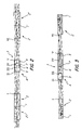
- FIG. 2 A schematic longitudinal section through an initial model of an image transmission system according to the invention, in which the additional lens system is formed as a threesome with a biconvex middle lens and convex/concave outer lenses.
- FIG. 3 An image transmission system in accordance with a second model, in which the middle lens of the threesome is formed as a spherical lens.
- FIG. 4 A third model of an image transmission system in accordance with the invention, in which the middle lens of the threesome is formed as a biconcave lens and the outer lenses as biconvex lenses.
- FIG. 5 A schematic longitudinal section through a fourth model of an image transmission system in accordance with the invention, in which the additional lens system consists of two pairs whose middle lens is biconvex and whose outer lenses are concave/convex.
- FIG. 1 shows schematically the complete arrangement of the lenses in an endoscope.
- the illustrated optical system consists altogether of seven image transmission systems, each extending from one inter-image plane to the next. Because the inter-image planes lie in the center plane 1 of the rod lenses 2 , every image transmission system in turn has two “half” rod lenses 2 and each has an additional lens system 3 .
- the image transmission system shown in FIG. 2 consists of two plano-convex rod lenses 2 shaped as spherical lenses and one additional lens system 3 formed as a threesome 4 and arranged symmetrically between the two rod lenses. Because each image transmission system consists of two plano-convex rod lenses 2 in the model of FIG. 2 , in which two rod lenses 2 of two sequentially arranged image transmission systems are joined to form one common spherical lens, the reference numbers referring to a second system are accompanied with an “prime” sign (′).
- the following possibilities for arranging and forming the rod lenses are available for setting up the illustrated image transmission systems:
- the image transmission system has only one plano-convex rod lens 2 , whereby the plane terminal surface forms the beginning or the end of the image transmission system.
- the image transmission system has two plano-convex rod lenses 2 whose plane ends forms the beginning and end of the image transmission system.
- plano-convex rod lenses 2 of two directly sequential image transmission systems are cemented together at their plane terminal surfaces.
- the rod lenses 2 of two directly sequentially arranged image transmission systems are formed as one-piece biconvex rod lenses.
- the first and last rod lenses 2 can be formed in abbreviated form in an endoscope in order to avoid having an inter-image surface coincide directly with the plane terminal surface of this rod lens 2 , because soiling of this surface and/or various damage could be a direct consequence.
- the spherical lenses that form the rod lenses 2 are distinguished in that they have the same curvature radius at both terminal surfaces and the length of each rod lens 2 is essentially equal to the doubled curvature radius of the terminal surfaces of the rod lenses 2 .
- the threesome 4 of the additional lens system 3 consists of two identical outer lenses 5 , which are formed as concave/convex meniscus lenses.
- the middle lens 6 positioned between the two outer lenses 5 and cemented to them, is formed as a biconvex lens.
- FIG. 2 shows the path of the beam.
- the interim images are situated in the center plane of the spherical lenses.
- This diaphragm plane of the image transmission system is situated in the center plane 7 of the middle lens 6 .
- FIG. 3 shows a particularly advantageous demonstration of the model in accordance with FIG. 2 , with a biconvex middle lens 6 for the threesome 4 .
- the middle lens 6 as well as the two rod lenses 2 are formed as spherical lenses whose terminal surfaces both have the same curvature radius and whose length is twice as great as the curvature radius of their two terminal surfaces.
- the diaphragm plane of the image transmission system is situated in the center plane 7 of the middle lens 6 formed as a spherical lens.
- the outer lenses of the additional lens system are formed as biconvex lenses and of the (threesome) or two (pairs) middle lens(es) are formed as biconcave lens(es), where n m is the refractive index of the middle lens(es) and n a the refractive index of the outer lenses.
- the fourth model of an image transmission system is distinguished from those of FIGS. 2 through 4 in that the additional lens system 3 arranged symmetrically between the two rod lenses 2 is not formed as a threesome 4 , but rather consists of two pairs 8 arranged at a distance from one another.
- the outer lenses 5 consist of convex/concave meniscus lenses, while the middle lenses 6 are formed as biconvex or plano-convex lenses.
- the outer lenses 5 it is possible to form the outer lenses 5 as biconvex or plano-convex lenses, while the inner lenses 6 are formed as biconcave, plano-concave, plano-convex, or convex/concave lenses.
- Tables 1 and 2 refer to a model in accordance with FIG. 2
- the examples in Tables 3 and 4 to a model in accordance with FIG. 3
- the examples in Tables 5 and 6 to the model in accordance with FIG. 4 .
- the optically effective surfaces indicated in the tables are labeled in FIGS. 2 through 4 with Roman numerals I through IV.
- the values for the Abbé counts are rounded off in the tables to one decimal place. The precise numerical values along with variations of these indicated values can be easily obtained by using customary optic design programs.
- the schematically illustrated image transmission systems are distinguished in that the use of spherical lenses as rod lenses 2 makes them simple and economical to produce, and thus an especially good correction of the image field curvature is achieved.
- the individual lenses can be constructed from several parts.
- the data of any other lenses employed can be adapted as necessary for the use of multi-part lenses and/or for the arrangement of an air space between two lenses.
Landscapes
- Physics & Mathematics (AREA)
- General Physics & Mathematics (AREA)
- Optics & Photonics (AREA)
- Astronomy & Astrophysics (AREA)
- Lenses (AREA)
- Instruments For Viewing The Inside Of Hollow Bodies (AREA)
Applications Claiming Priority (3)
| Application Number | Priority Date | Filing Date | Title |
|---|---|---|---|
| DE19910050.0 | 1999-03-08 | ||
| DE19910050A DE19910050C2 (de) | 1999-03-08 | 1999-03-08 | Bildübertragungssystem für Endoskope und dgl. Sehrohre sowie Verfahren zur Herstellung eines Bildübertragungssystems |
| PCT/EP2000/001980 WO2000054089A1 (fr) | 1999-03-08 | 2000-03-07 | Systeme de transmission d'images pour endoscopes et procede de production d'une lentille en forme de barre |
Related Parent Applications (1)
| Application Number | Title | Priority Date | Filing Date |
|---|---|---|---|
| PCT/EP2000/001980 Continuation WO2000054089A1 (fr) | 1999-03-08 | 2000-03-07 | Systeme de transmission d'images pour endoscopes et procede de production d'une lentille en forme de barre |
Publications (2)
| Publication Number | Publication Date |
|---|---|
| US20020057501A1 US20020057501A1 (en) | 2002-05-16 |
| US7002741B2 true US7002741B2 (en) | 2006-02-21 |
Family
ID=7900047
Family Applications (1)
| Application Number | Title | Priority Date | Filing Date |
|---|---|---|---|
| US09/949,608 Expired - Lifetime US7002741B2 (en) | 1999-03-08 | 2001-09-10 | Image transmission system for endoscopes and method of producing a rod lens |
Country Status (4)
| Country | Link |
|---|---|
| US (1) | US7002741B2 (fr) |
| EP (1) | EP1159643B1 (fr) |
| DE (2) | DE19910050C2 (fr) |
| WO (1) | WO2000054089A1 (fr) |
Cited By (6)
| Publication number | Priority date | Publication date | Assignee | Title |
|---|---|---|---|---|
| US20050240079A1 (en) * | 2003-04-25 | 2005-10-27 | Horst Baholzer | Endoscope |
| US20080239480A1 (en) * | 2004-02-13 | 2008-10-02 | Olympus Winter & Ibe Gmbh | Endoscope Relay Lens |
| US20090270683A1 (en) * | 2000-01-14 | 2009-10-29 | Intuitive Surgical, Inc. | Endoscope |
| US20140313578A1 (en) * | 2012-01-05 | 2014-10-23 | Olympus Winter & Ibe Gmbh | Relay set for an endoscope and an endoscope |
| US11067788B2 (en) * | 2016-06-17 | 2021-07-20 | Olympus Corporation | Bright relay optical system, and optical system for rigid endoscope and rigid endoscope using the same |
| US11079588B2 (en) * | 2016-06-17 | 2021-08-03 | Olympus Corporation | Relay optical system, and optical system for rigid endoscope and rigid endoscope using the same |
Families Citing this family (11)
| Publication number | Priority date | Publication date | Assignee | Title |
|---|---|---|---|---|
| EP1301118B1 (fr) | 2000-07-14 | 2006-09-06 | Xillix Technologies Corp. | Systeme video compact d'endoscopie en fluorescence |
| US20060241496A1 (en) | 2002-01-15 | 2006-10-26 | Xillix Technologies Corp. | Filter for use with imaging endoscopes |
| US20090303317A1 (en) | 2006-02-07 | 2009-12-10 | Novadaq Technologies Inc. | Near infrared imaging |
| US9433341B2 (en) * | 2012-03-26 | 2016-09-06 | Karl Storz Imaging, Inc. | Compensated relays for reducing number of elements in rod lens endoscopes |
| DE102012214703B4 (de) * | 2012-08-17 | 2024-09-05 | Carl Zeiss Meditec Ag | Operationsmikroskop-Objektiv mit einstellbarer Schnittweite, Wechsel-objektiv sowie Operationsmikroskop |
| KR20170129282A (ko) * | 2013-05-15 | 2017-11-24 | 노바다크 테크놀러지즈 인코포레이티드 | 고 보정식 릴레이 시스템 |
| CN105116520B (zh) * | 2015-09-25 | 2017-10-03 | 宁波大学 | 一种应用硫系玻璃的红外中继转像镜头 |
| US10293122B2 (en) | 2016-03-17 | 2019-05-21 | Novadaq Technologies ULC | Endoluminal introducer with contamination avoidance |
| JP6602738B2 (ja) * | 2016-10-19 | 2019-11-06 | 株式会社タムロン | 観察光学系、観察撮像装置、観察撮像システム、結像レンズ系及び観察光学系の調整方法 |
| DE102017122556A1 (de) | 2017-09-28 | 2019-03-28 | Karl Storz Se & Co. Kg | Bildübertragungssystem für ein Endoskop, Endoskop sowie Relaislinsensystem |
| CN115415887A (zh) * | 2022-10-10 | 2022-12-02 | 福建光旭科技有限公司 | 一种棒镜加工工艺 |
Citations (21)
| Publication number | Priority date | Publication date | Assignee | Title |
|---|---|---|---|---|
| US1443150A (en) * | 1921-05-31 | 1923-01-23 | Schimmel Fridolin | Grinding tool |
| GB954629A (en) * | 1959-07-16 | 1964-04-08 | Harold Horace Hopkins | Improvements in or relating to optical systems |
| GB1443150A (en) * | 1972-12-06 | 1976-07-21 | Nat Res Dev | Optical devices |
| US4025155A (en) * | 1974-12-10 | 1977-05-24 | Olympus Optical Co., Ltd. | Image-transmitting optical system |
| DE2837119A1 (de) * | 1977-09-22 | 1979-03-29 | Daniel Louis Legrand | Optisches system zur beobachtung einer kammer mit dicken waenden |
| US4168882A (en) * | 1975-04-30 | 1979-09-25 | The Secretary Of State For Social Services In Her Britannic Majesty's Government Of The United Kingdom Of Great Britain And Northern Ireland | Optical systems |
| GB2081923A (en) * | 1980-08-15 | 1982-02-24 | American Optical Corp | Dynamic image enhancer for fibrescopes |
| US4354730A (en) * | 1979-06-25 | 1982-10-19 | Metallisations Et Traitements Optiques M.T.O. | Optical relay used for transferring an image from one point to another along an optical axis |
| US4784118A (en) * | 1987-04-28 | 1988-11-15 | Endotherapeutics | Optical viewing device |
| US4961802A (en) * | 1987-11-10 | 1990-10-09 | Matsushita Electric Industrial Co., Ltd. | Method of manufacturing a lens array for reading information |
| EP0452053A1 (fr) * | 1990-04-12 | 1991-10-16 | Mckinley Optics Incorporated | Lentille de relais pour endoscope |
| US5097359A (en) * | 1990-04-12 | 1992-03-17 | Mckinley Optics, Inc. | Endoscope relay lens configuration |
| US5097759A (en) * | 1991-03-18 | 1992-03-24 | Vie De France Corporation | Sous vide reheating device |
| EP0310640B1 (fr) * | 1987-03-19 | 1992-08-05 | MED Inventio AG | Systeme de lentilles de relais |
| US5142410A (en) * | 1989-04-14 | 1992-08-25 | Olympus Optical Co., Ltd. | Image relaying optical system |
| US5206759A (en) * | 1989-04-14 | 1993-04-27 | Olympus Optical Co., Ltd. | Image relaying optical system |
| US5233473A (en) * | 1990-10-09 | 1993-08-03 | Olympus Optical Co., Ltd. | Optical system for endoscopes |
| US5416638A (en) * | 1992-02-06 | 1995-05-16 | Linvatec Corporation | Disposable endoscope |
| US5684629A (en) * | 1993-10-05 | 1997-11-04 | Monadnock Optics, Inc. | Optical system for endoscope |
| US5805345A (en) * | 1994-07-12 | 1998-09-08 | Olympus Optical Co., Ltd. | Image transmission optical system |
| US6327096B1 (en) * | 1997-04-30 | 2001-12-04 | Olympus Optical Co., Ltd. | Set of lens system |
Family Cites Families (3)
| Publication number | Priority date | Publication date | Assignee | Title |
|---|---|---|---|---|
| SU686725A1 (ru) * | 1977-03-14 | 1979-09-28 | Всесоюзный Научно-Исследовательский Институт Медицинского Приборостроения | Оптическа система эндоскопа |
| US4391621A (en) * | 1981-03-23 | 1983-07-05 | American Optical Corporation | Method of making lenses having a spherical face |
| JPS57168212A (en) * | 1982-03-15 | 1982-10-16 | Olympus Optical Co Ltd | Clear and hard endoscope |
-
1999
- 1999-03-08 DE DE19910050A patent/DE19910050C2/de not_active Expired - Lifetime
-
2000
- 2000-03-07 WO PCT/EP2000/001980 patent/WO2000054089A1/fr not_active Ceased
- 2000-03-07 DE DE50003535T patent/DE50003535D1/de not_active Expired - Lifetime
- 2000-03-07 EP EP00912561A patent/EP1159643B1/fr not_active Expired - Lifetime
-
2001
- 2001-09-10 US US09/949,608 patent/US7002741B2/en not_active Expired - Lifetime
Patent Citations (22)
| Publication number | Priority date | Publication date | Assignee | Title |
|---|---|---|---|---|
| US1443150A (en) * | 1921-05-31 | 1923-01-23 | Schimmel Fridolin | Grinding tool |
| GB954629A (en) * | 1959-07-16 | 1964-04-08 | Harold Horace Hopkins | Improvements in or relating to optical systems |
| GB1443150A (en) * | 1972-12-06 | 1976-07-21 | Nat Res Dev | Optical devices |
| US4025155A (en) * | 1974-12-10 | 1977-05-24 | Olympus Optical Co., Ltd. | Image-transmitting optical system |
| US4168882A (en) * | 1975-04-30 | 1979-09-25 | The Secretary Of State For Social Services In Her Britannic Majesty's Government Of The United Kingdom Of Great Britain And Northern Ireland | Optical systems |
| DE2837119A1 (de) * | 1977-09-22 | 1979-03-29 | Daniel Louis Legrand | Optisches system zur beobachtung einer kammer mit dicken waenden |
| US4354730A (en) * | 1979-06-25 | 1982-10-19 | Metallisations Et Traitements Optiques M.T.O. | Optical relay used for transferring an image from one point to another along an optical axis |
| GB2081923A (en) * | 1980-08-15 | 1982-02-24 | American Optical Corp | Dynamic image enhancer for fibrescopes |
| EP0310640B1 (fr) * | 1987-03-19 | 1992-08-05 | MED Inventio AG | Systeme de lentilles de relais |
| US4784118A (en) * | 1987-04-28 | 1988-11-15 | Endotherapeutics | Optical viewing device |
| US4961802A (en) * | 1987-11-10 | 1990-10-09 | Matsushita Electric Industrial Co., Ltd. | Method of manufacturing a lens array for reading information |
| US5142410A (en) * | 1989-04-14 | 1992-08-25 | Olympus Optical Co., Ltd. | Image relaying optical system |
| US5206759A (en) * | 1989-04-14 | 1993-04-27 | Olympus Optical Co., Ltd. | Image relaying optical system |
| US5097359A (en) * | 1990-04-12 | 1992-03-17 | Mckinley Optics, Inc. | Endoscope relay lens configuration |
| US5059009A (en) * | 1990-04-12 | 1991-10-22 | Mckinley Optics, Incorporated | Endoscope relay lens |
| EP0452053A1 (fr) * | 1990-04-12 | 1991-10-16 | Mckinley Optics Incorporated | Lentille de relais pour endoscope |
| US5233473A (en) * | 1990-10-09 | 1993-08-03 | Olympus Optical Co., Ltd. | Optical system for endoscopes |
| US5097759A (en) * | 1991-03-18 | 1992-03-24 | Vie De France Corporation | Sous vide reheating device |
| US5416638A (en) * | 1992-02-06 | 1995-05-16 | Linvatec Corporation | Disposable endoscope |
| US5684629A (en) * | 1993-10-05 | 1997-11-04 | Monadnock Optics, Inc. | Optical system for endoscope |
| US5805345A (en) * | 1994-07-12 | 1998-09-08 | Olympus Optical Co., Ltd. | Image transmission optical system |
| US6327096B1 (en) * | 1997-04-30 | 2001-12-04 | Olympus Optical Co., Ltd. | Set of lens system |
Cited By (11)
| Publication number | Priority date | Publication date | Assignee | Title |
|---|---|---|---|---|
| US20090270683A1 (en) * | 2000-01-14 | 2009-10-29 | Intuitive Surgical, Inc. | Endoscope |
| US8118730B2 (en) * | 2000-01-14 | 2012-02-21 | Intuitive Surgical Operations, Inc. | Endoscope |
| US9039609B2 (en) | 2000-01-14 | 2015-05-26 | Intuitive Surgical Operations, Inc. | Endoscope |
| US20050240079A1 (en) * | 2003-04-25 | 2005-10-27 | Horst Baholzer | Endoscope |
| US7448994B2 (en) * | 2003-04-25 | 2008-11-11 | Horst Baholzer | Endoscope |
| US20080239480A1 (en) * | 2004-02-13 | 2008-10-02 | Olympus Winter & Ibe Gmbh | Endoscope Relay Lens |
| US7515335B2 (en) * | 2004-02-13 | 2009-04-07 | Olympus Winter & Ibe Gmbh | Endoscope relay lens |
| US20140313578A1 (en) * | 2012-01-05 | 2014-10-23 | Olympus Winter & Ibe Gmbh | Relay set for an endoscope and an endoscope |
| US9817227B2 (en) * | 2012-01-05 | 2017-11-14 | Olympus Winter & Ibe Gmbh | Relay set for an endoscope and an endoscope |
| US11067788B2 (en) * | 2016-06-17 | 2021-07-20 | Olympus Corporation | Bright relay optical system, and optical system for rigid endoscope and rigid endoscope using the same |
| US11079588B2 (en) * | 2016-06-17 | 2021-08-03 | Olympus Corporation | Relay optical system, and optical system for rigid endoscope and rigid endoscope using the same |
Also Published As
| Publication number | Publication date |
|---|---|
| US20020057501A1 (en) | 2002-05-16 |
| EP1159643B1 (fr) | 2003-09-03 |
| DE19910050A1 (de) | 2000-09-28 |
| DE19910050C2 (de) | 2003-08-14 |
| WO2000054089A1 (fr) | 2000-09-14 |
| DE50003535D1 (de) | 2003-10-09 |
| EP1159643A1 (fr) | 2001-12-05 |
Similar Documents
| Publication | Publication Date | Title |
|---|---|---|
| US7002741B2 (en) | Image transmission system for endoscopes and method of producing a rod lens | |
| US7218454B2 (en) | Endoscope objective lens | |
| JP3051035B2 (ja) | 内視鏡用対物レンズ | |
| US5005960A (en) | Relay lens system with four optical elements in symmetrical arrangement | |
| US6618207B2 (en) | Endoscope lens, and an endoscope equipped with such a lens | |
| JPS56133711A (en) | Photographic lens of short overall length | |
| JPH0980305A (ja) | 内視鏡対物レンズ | |
| US7724430B2 (en) | Rigid endoscope | |
| US6545802B2 (en) | Integrated optical system for endoscopes and the like | |
| JP2702520B2 (ja) | 小型ズームレンズ | |
| JPH0580649B2 (fr) | ||
| JPS594685B2 (ja) | コンパクトナズ−ムレンズ | |
| US7515335B2 (en) | Endoscope relay lens | |
| US4529267A (en) | Illuminating system for endoscopes | |
| JPH0414324B2 (fr) | ||
| JPH01124810A (ja) | 像伝達光学系 | |
| JP2558333B2 (ja) | 内視鏡対物光学系 | |
| JPS5834813B2 (ja) | アタツチメントレンズ | |
| JP2003524204A (ja) | 内視鏡などのための統合型光学系 | |
| JPS6048011B2 (ja) | 望遠率の小さい望遠レンズ | |
| JP3642444B2 (ja) | 接眼レンズ | |
| JPS6120015A (ja) | 像伝達光学系 | |
| US5488512A (en) | Color corrected ocular | |
| CN223640684U (zh) | 一种超高清内窥镜光学成像系统 | |
| TWI801148B (zh) | 定焦鏡頭 |
Legal Events
| Date | Code | Title | Description |
|---|---|---|---|
| AS | Assignment |
Owner name: KARL STORZ GMBH & CO. KG, GERMANY Free format text: ASSIGNMENT OF ASSIGNORS INTEREST;ASSIGNOR:LEI, FANG;REEL/FRAME:012336/0826 Effective date: 20011108 |
|
| FEPP | Fee payment procedure |
Free format text: PAYOR NUMBER ASSIGNED (ORIGINAL EVENT CODE: ASPN); ENTITY STATUS OF PATENT OWNER: LARGE ENTITY |
|
| STCF | Information on status: patent grant |
Free format text: PATENTED CASE |
|
| CC | Certificate of correction | ||
| FEPP | Fee payment procedure |
Free format text: PAYOR NUMBER ASSIGNED (ORIGINAL EVENT CODE: ASPN); ENTITY STATUS OF PATENT OWNER: LARGE ENTITY Free format text: PAYER NUMBER DE-ASSIGNED (ORIGINAL EVENT CODE: RMPN); ENTITY STATUS OF PATENT OWNER: LARGE ENTITY |
|
| FPAY | Fee payment |
Year of fee payment: 4 |
|
| FPAY | Fee payment |
Year of fee payment: 8 |
|
| FPAY | Fee payment |
Year of fee payment: 12 |
|
| AS | Assignment |
Owner name: KARL STORZ SE & CO. KG, GERMANY Free format text: CHANGE OF NAME;ASSIGNOR:KARL STORZ GMBH & CO. KG;REEL/FRAME:045373/0627 Effective date: 20170911 |