US7007748B2 - Indirect water heater and method of manufacturing same - Google Patents
Indirect water heater and method of manufacturing same Download PDFInfo
- Publication number
- US7007748B2 US7007748B2 US10/677,038 US67703803A US7007748B2 US 7007748 B2 US7007748 B2 US 7007748B2 US 67703803 A US67703803 A US 67703803A US 7007748 B2 US7007748 B2 US 7007748B2
- Authority
- US
- United States
- Prior art keywords
- tube
- fitting
- coiled
- water
- storage tank
- Prior art date
- Legal status (The legal status is an assumption and is not a legal conclusion. Google has not performed a legal analysis and makes no representation as to the accuracy of the status listed.)
- Expired - Lifetime, expires
Links
- XLYOFNOQVPJJNP-UHFFFAOYSA-N water Substances O XLYOFNOQVPJJNP-UHFFFAOYSA-N 0.000 title claims abstract description 193
- 238000004519 manufacturing process Methods 0.000 title description 7
- 238000003860 storage Methods 0.000 claims description 63
- 230000002787 reinforcement Effects 0.000 claims description 60
- 238000010438 heat treatment Methods 0.000 claims description 24
- 238000000034 method Methods 0.000 claims description 19
- 239000012530 fluid Substances 0.000 claims description 14
- 239000008236 heating water Substances 0.000 claims description 11
- 230000003134 recirculating effect Effects 0.000 claims description 7
- 230000008878 coupling Effects 0.000 claims description 4
- 238000010168 coupling process Methods 0.000 claims description 4
- 238000005859 coupling reaction Methods 0.000 claims description 4
- 238000003466 welding Methods 0.000 claims 2
- 229910000975 Carbon steel Inorganic materials 0.000 description 10
- 239000010962 carbon steel Substances 0.000 description 10
- 238000012546 transfer Methods 0.000 description 7
- 239000000463 material Substances 0.000 description 6
- 230000003247 decreasing effect Effects 0.000 description 5
- 230000008569 process Effects 0.000 description 5
- 239000007769 metal material Substances 0.000 description 4
- 230000008859 change Effects 0.000 description 3
- 238000009434 installation Methods 0.000 description 3
- 239000010935 stainless steel Substances 0.000 description 3
- 229910001220 stainless steel Inorganic materials 0.000 description 3
- 239000000853 adhesive Substances 0.000 description 2
- 230000001070 adhesive effect Effects 0.000 description 2
- 235000012206 bottled water Nutrition 0.000 description 2
- 239000003651 drinking water Substances 0.000 description 2
- 230000006872 improvement Effects 0.000 description 2
- 238000005096 rolling process Methods 0.000 description 2
- RYGMFSIKBFXOCR-UHFFFAOYSA-N Copper Chemical compound [Cu] RYGMFSIKBFXOCR-UHFFFAOYSA-N 0.000 description 1
- 241001417935 Platycephalidae Species 0.000 description 1
- 229910000831 Steel Inorganic materials 0.000 description 1
- 230000005494 condensation Effects 0.000 description 1
- 238000009833 condensation Methods 0.000 description 1
- 239000004020 conductor Substances 0.000 description 1
- 229910052802 copper Inorganic materials 0.000 description 1
- 239000010949 copper Substances 0.000 description 1
- 238000005260 corrosion Methods 0.000 description 1
- 230000007797 corrosion Effects 0.000 description 1
- 238000013461 design Methods 0.000 description 1
- 238000009413 insulation Methods 0.000 description 1
- 238000012986 modification Methods 0.000 description 1
- 230000004048 modification Effects 0.000 description 1
- 230000003647 oxidation Effects 0.000 description 1
- 238000007254 oxidation reaction Methods 0.000 description 1
- 239000010959 steel Substances 0.000 description 1
- 238000013517 stratification Methods 0.000 description 1
- 238000006467 substitution reaction Methods 0.000 description 1
Images


Classifications
-
- F—MECHANICAL ENGINEERING; LIGHTING; HEATING; WEAPONS; BLASTING
- F24—HEATING; RANGES; VENTILATING
- F24D—DOMESTIC- OR SPACE-HEATING SYSTEMS, e.g. CENTRAL HEATING SYSTEMS; DOMESTIC HOT-WATER SUPPLY SYSTEMS; ELEMENTS OR COMPONENTS THEREFOR
- F24D3/00—Hot-water central heating systems
- F24D3/08—Hot-water central heating systems in combination with systems for domestic hot-water supply
- F24D3/082—Hot water storage tanks specially adapted therefor
-
- F—MECHANICAL ENGINEERING; LIGHTING; HEATING; WEAPONS; BLASTING
- F28—HEAT EXCHANGE IN GENERAL
- F28D—HEAT-EXCHANGE APPARATUS, NOT PROVIDED FOR IN ANOTHER SUBCLASS, IN WHICH THE HEAT-EXCHANGE MEDIA DO NOT COME INTO DIRECT CONTACT
- F28D20/00—Heat storage plants or apparatus in general; Regenerative heat-exchange apparatus not covered by groups F28D17/00 or F28D19/00
- F28D20/0034—Heat storage plants or apparatus in general; Regenerative heat-exchange apparatus not covered by groups F28D17/00 or F28D19/00 using liquid heat storage material
-
- F—MECHANICAL ENGINEERING; LIGHTING; HEATING; WEAPONS; BLASTING
- F28—HEAT EXCHANGE IN GENERAL
- F28D—HEAT-EXCHANGE APPARATUS, NOT PROVIDED FOR IN ANOTHER SUBCLASS, IN WHICH THE HEAT-EXCHANGE MEDIA DO NOT COME INTO DIRECT CONTACT
- F28D7/00—Heat-exchange apparatus having stationary tubular conduit assemblies for both heat-exchange media, the media being in contact with different sides of a conduit wall
- F28D7/02—Heat-exchange apparatus having stationary tubular conduit assemblies for both heat-exchange media, the media being in contact with different sides of a conduit wall the conduits being helically coiled
- F28D7/024—Heat-exchange apparatus having stationary tubular conduit assemblies for both heat-exchange media, the media being in contact with different sides of a conduit wall the conduits being helically coiled the conduits of only one medium being helically coiled tubes, the coils having a cylindrical configuration
-
- F—MECHANICAL ENGINEERING; LIGHTING; HEATING; WEAPONS; BLASTING
- F28—HEAT EXCHANGE IN GENERAL
- F28F—DETAILS OF HEAT-EXCHANGE AND HEAT-TRANSFER APPARATUS, OF GENERAL APPLICATION
- F28F9/00—Casings; Header boxes; Auxiliary supports for elements; Auxiliary members within casings
- F28F9/02—Header boxes; End plates
- F28F9/0246—Arrangements for connecting header boxes with flow lines
-
- Y—GENERAL TAGGING OF NEW TECHNOLOGICAL DEVELOPMENTS; GENERAL TAGGING OF CROSS-SECTIONAL TECHNOLOGIES SPANNING OVER SEVERAL SECTIONS OF THE IPC; TECHNICAL SUBJECTS COVERED BY FORMER USPC CROSS-REFERENCE ART COLLECTIONS [XRACs] AND DIGESTS
- Y02—TECHNOLOGIES OR APPLICATIONS FOR MITIGATION OR ADAPTATION AGAINST CLIMATE CHANGE
- Y02E—REDUCTION OF GREENHOUSE GAS [GHG] EMISSIONS, RELATED TO ENERGY GENERATION, TRANSMISSION OR DISTRIBUTION
- Y02E60/00—Enabling technologies; Technologies with a potential or indirect contribution to GHG emissions mitigation
- Y02E60/14—Thermal energy storage
Definitions
- the present invention relates to an indirect water heater and, more particularly, to a heat exchange assembly adapted for use in a water tank.
- U.S. Pat. No. 5,485,879 to Lannes discloses a combined water heating system for domestic or commercial use capable of heating water for consumption as well as for space heating.
- the '879 system comprises a heat exchanger incorporated into a standard, glass-lined water heater system. While the '879 system represents a significant improvement over prior systems, continued improvements are sought.
- this invention provides a heat exchange assembly adapted for use in a water tank.
- the heat exchange assembly includes a tube having end portions and a coiled portion between the end portions.
- a fitting is connected to at least one of the end portions of the tube.
- the fitting has an end configured to extend through an opening in the water tank, and a surface positioned to limit the extension of the end through the opening in the water tank.
- the fitting also has an opposite end defining a bore configured to receive one of the end portions of the tube and to limit the extension of the end portion of the tube into the opposite end of the fitting. The bore extends axially beyond the surface of the fitting.
- a coiled heat exchanger configured for use in a water heater.
- the coiled heat exchanger includes a coiled tube for directing the flow of fluid through the heat exchanger.
- the coiled tube has a tube outer diameter and a coil inner radius, wherein the ratio of the outer diameter of the tube to the coil inner radius is about 0.19:1 or greater.
- a system for heating water includes a water storage tank adapted to contain a water supply, and at least one tube connected to contain a recirculating water supply.
- the tube is mounted within the water storage tank and has at least one end portion fixed with respect to the water storage tank, and a coiled portion extending from the end portion.
- a fitting is connected to the end portion of the tube and to the water storage tank. The fitting is oriented along a first direction and configured to reduce movement of the end portion of the tube with respect to the water storage tank along the first direction.
- a reinforcement member is coupled to the coiled portion of the tube and to the water storage tank. The reinforcement member is oriented along a second direction substantially perpendicular to the first direction and configured to reduce movement of the coiled portion of the tube with respect to the water storage tank along the second direction.
- a method for mounting the tube assembly within the water storage tank includes the step of coupling a fitting of the tube assembly to the water storage tank along a first direction, thereby reducing movement of the tube assembly with respect to the water storage tank along the first direction.
- the method further includes the step of attaching a reinforcement member of the tube assembly to the water storage tank along a second direction substantially perpendicular to the first direction, thereby reducing movement of the tube assembly with respect to the water storage tank along the second direction.
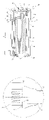
- FIG. 1 is a front cutaway view of an exemplary embodiment of a system for heating water including a water tank according to aspects of this invention
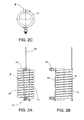
- FIG. 2A is a front view of an exemplary embodiment of a heat exchange assembly illustrating a coiled tube, fittings, support members, and a reinforcement member according to aspects of this invention
- FIG. 2B is a right side view of the heat exchange assembly illustrated in FIG. 2A ;
- FIG. 2C is a top view of the heat exchange assembly illustrated in FIG. 2A ;
- FIG. 3 is a detail view of the heat exchange assembly illustrated in FIG. 2A showing a support member welded to the coiled tube;
- FIG. 4 is a detail view of the heat exchange assembly illustrated in FIG. 2C showing the location of the reinforcement member toward the center of the coiled tube;
- FIG. 5A is a front view of another exemplary embodiment of a heat exchange assembly illustrating a coiled tube, fittings, support members, and a reinforcement member according to aspects of this invention
- FIG. 5B is a right side view of the heat exchange assembly illustrated in FIG. 5A ;
- FIG. 5C is a top view of the heat exchange assembly illustrated in FIG. 5A ;
- FIG. 6 is a detail view of the heat exchange assembly illustrated in FIG. 5B showing the fitting connected to an end portion of the tube;
- FIG. 7A is a front view of the coiled tube component of the heat exchange assembly illustrated in FIG. 2A ;
- FIG. 7B is a right side view of the coiled tube illustrated in FIG. 7A ;
- FIG. 7C is a top view of the coiled tube illustrated in FIG. 7A ;
- FIG. 8A is a side view of the fitting component of the heat exchange assembly illustrated in FIGS. 2A and 5A ;
- FIG. 8B is a cross-sectional side view of the fitting illustrated in FIG. 8A ;
- FIG. 8C is an end view of the fitting illustrated in FIG. 8A ;
- FIG. 9A is a side view of the reinforcement member component of the heat exchange assembly illustrated in FIGS. 2A and 5A ;
- FIG. 9B is an end view of the reinforcement member illustrated in FIG. 9A ;
- FIG. 10A is a side view of the support member component of the heat exchange assembly illustrated in FIGS. 2A and 5A ;
- FIG. 10B is an end view of the support member illustrated in FIG. 10A ;
- FIG. 11A top view of the water tank head component of the water heating system illustrated in FIG. 1 ;
- FIG. 11B is a side view of the water tank head illustrated in FIG. 11A ;
- FIG. 12A is a top view of a weld plate component of the water heating system illustrated in FIG. 1 ;
- FIG. 12B is a side view of the weld plate illustrated in FIG. 12A ;
- FIG. 13 is a top view of an exemplary embodiment of a system for heating water including the heat exchange assembly illustrated in FIG. 2A or 5 A according to aspects of this invention
- FIG. 14 is a top view of another exemplary embodiment of a system for heating water including the heat exchange assembly illustrated in FIG. 2A or 5 A according to aspects of this invention
- FIG. 15 is a cross-sectional detail view illustrating the weld plate of FIG. 12A securing the reinforcement member of FIG. 9A to the water tank head of FIG. 11A ;
- FIG. 16 is a cross-sectional detail view illustrating another embodiment of the weld plate of FIG. 12A securing the reinforcement member of FIG. 9A to the water tank head of FIG. 11A .
- a heat exchange assembly 10 adapted for use in a water tank 12 is provided.
- the heat exchange assembly 10 includes a tube 14 having end portions 16 and a coiled portion 15 between the end portions 16 .
- a fitting 18 is connected to each of the end portions 16 of the tube 14 .
- Each fitting 18 has an end 20 configured to extend through an opening 22 in the water tank 12 and a surface 24 positioned to limit the extension of the end 20 through the opening 22 in the water tank 12 .
- Each fitting 18 also has an opposite end 26 defining a bore 28 configured to receive one of the end portions 16 of the tube 14 and to limit the extension of the end portion 16 of the tube 14 into the opposite end 26 of the fitting 18 .
- the bore 28 extends axially beyond the surface 24 of the fitting 18 .
- a coiled heat exchanger 10 configured for use in a water heater 12 is provided.
- the coiled heat exchanger 10 includes a coiled tube 14 for directing the flow of fluid through the heat exchanger 10 .
- the coiled tube 14 has a tube outer diameter “D” and a coil inner radius “R,” wherein the ratio of the outer diameter “D” of the tube 14 to the coil inner radius “R” is about 0.19:1 or greater.
- a system 30 for heating water includes a water storage tank 12 adapted to contain a water supply and a tube 14 connected to contain a recirculating water supply.
- the tube 14 is mounted within the water storage tank 12 and has end portions 16 fixed with respect to the water storage tank 12 , and a coiled portion 15 extending from the end portions 16 .
- a fitting 18 is connected to each end portion 16 of the tube 14 and to the water storage tank 12 .
- the fitting 18 is oriented along a first direction “A” and configured to reduce movement of the tube 14 with respect to the water storage tank 12 along the first direction “A.”
- a reinforcement member 32 is coupled to the coiled portion 15 of the tube 14 and to the water storage tank 12 .
- the reinforcement member 32 is oriented along a second direction “B” substantially perpendicular to the first direction “A” and is configured to reduce movement of the coiled portion 15 of the tube 14 with respect to the water storage tank 12 along the second direction “B.”
- a method for mounting the tube 14 within the water storage 12 tank includes the step of connecting a fitting 18 to the tube 14 and to the water storage tank 12 .
- the fitting 18 is oriented along a first direction “A” and configured to reduce movement of the tube 14 with respect to the water storage tank 12 along the first direction “A.”
- the method further includes the step of attaching a reinforcement member 32 to the tube 14 and to the water storage tank 12 .
- the reinforcement member 32 is oriented along a second direction “B” substantially perpendicular to the first direction “A” and configured to reduce movement of the tube 14 with respect to the water storage tank 12 along the second direction “B.”
- FIG. 1 a heat exchange assembly embodying exemplary aspects of this invention is generally designated by the numeral “10.”
- FIG. 1 depicts a commercial or residential water heater. However, the descriptions herein apply to commercial water heaters and residential or domestic water heaters, as well as other heat transfer systems.
- the heat exchange assembly 10 is adapted for use in a water tank 12 provided with a cover portion such as a head assembly 34 , and a base 35 .
- the heat exchange assembly 10 includes a tube 14 having end portions 16 and a coiled portion 15 between the end portions 16 .
- a fitting 18 is connected to each of the end portions 16 of the tube 14 and to the water storage tank 12 .
- the fittings 18 are oriented along a first direction “A” and configured to reduce movement of the tube 14 with respect to the water storage tank 12 along the first direction “A.”
- An outer jacket 36 is configured to surround the water tank 12 . The space between the outer wall surface of the water tank 12 and the inner wall surface of the outer jacket 36 will be at least partially filled with insulation (not shown).
- a reinforcement member 32 is attached to the tube 14 and to the water storage tank 12 .
- the reinforcement member 32 is oriented along a second direction “B” substantially perpendicular to the first direction “A,” and is configured to reduce movement of the tube 14 with respect to the water storage tank 12 along the second direction “B.”
- the exemplary reinforcement member 32 is attached to the tube 14 via a weld. However, such attachment is not limited to a weld, as the reinforcement member 32 may be attached to the coiled tube 14 via fasteners, high-temperature waterproof adhesive, or any other suitable means of securing the components.
- the exemplary reinforcement member 32 is attached to the water storage tank 12 also via a weld, as will be described subsequently with reference to FIGS. 15 and 16 .
- the head assembly 34 and the base 35 are welded to the top and bottom (respectively) of the water tank 12 to form watertight seals for the containment of water (or other fluids) within the water tank 12 .
- the head assembly is configured to include a cold water supply 38 and a hot water outlet 40 .
- the water tank 12 is equipped with multiple sacrificial anodes 42 to protect the tank 12 from corrosion.
- FIGS. 2A–2C illustrate a heat exchange assembly 10 specifically sized for residential or domestic water heaters.
- the tube 14 is coiled for directing the flow of fluid through the heat exchange assembly 10 .
- a fitting 18 is connected to each of the end portions 16 of the tube 14 , and a reinforcement member 32 is also attached to the tube 14 .
- Support members 44 contact the coils of the tube 14 .
- the coils are spaced evenly apart, as represented by gaps 46 .
- the size of the gaps 46 may be increased or decreased to accommodate various dimensional constraints.
- the size of the exemplary gaps 46 may be 3 ⁇ 8 inch.
- the size of the gaps 46 is not limited to 3 ⁇ 8 inch, and may be any other suitable larger or smaller dimension.
- the support members 44 By maintaining even spacing between adjacent coils 15 of the tube 14 , the support members 44 reduce or eliminate any noise caused by coil vibration.
- the support members 44 also maximize the heat transfer surface area by preventing contact between adjacent coils 15 . Furthermore, even spacing between the coils 15 improves water circulation between adjacent coils 15 , thereby decreasing stratification by permitting horizontal water flow during operation of the water heating system 30 .
- the support members 44 are welded on alternating sides at every convolution of the coiled tube 14 .
- the present invention is not limited to welds, as the support members 44 may be attached to the coiled tube 14 via fasteners, high-temperature waterproof adhesive, or any other suitable means of securing the components.
- Such a configuration reduces movement of the coils 15 with respect to one another, assisting in securing the overall stability of the heat exchange assembly 10 within the water tank 12 .
- FIG. 3 which illustrates an embodiment in which a support member 44 is tack welded to the coiled tube 14
- the weld has been minimized to reduce oxidation in the tank and to reduce labor costs.
- tack welds to alternating sides of support member 44 on adjacent coils of the coiled tube 14
- the structural integrity of the support is maintained while reducing the amount of weld in the tank.
- the support member 44 is prevented from rolling about its longitudinal axis. Such rolling may be more apt to occur if the support member 44 were to be welded along only one of its sides.
- every convolution of the coiled tube 14 is fixed to the support member 44 .
- FIG. 4 illustrates the location “C” of the reinforcement member 32 at the center of the convolution of the coiled tube 14 . More specifically, location “C” is the position at which the reinforcement member 32 is attached to the tube 14 via a weld.
- FIGS. 5A–5C illustrate a heat exchange assembly 100 specifically sized for commercial water heaters.
- the tube 114 is coiled for directing the flow of fluid through the heat exchange assembly 100 .
- a fitting 18 is connected to each of the end portions 116 of the tube 114 , and a reinforcement member 132 is also attached to the tube 114 .
- Support members 144 contact the coils of the tube 114 .
- the coils are spaced evenly apart, as represented by gaps 146 .
- the size of the gaps 146 may be increased or decreased to accommodate various dimensional constraints.
- the size of the exemplary gaps 146 may be 3 ⁇ 8 inch.
- the size of the gaps 146 is not limited to 3 ⁇ 8 inch, and may be any other suitable larger or smaller dimension.
- the components and configurations described herein with reference to FIGS. 1–4 and 6 – 15 apply to the heat exchange assembly 100 represented here as well.
- FIG. 6 illustrates a fitting 18 attached to an end portion 16 of tube 14 .
- the exemplary fitting 18 is welded to the end portion 16 of the tube 14 at weld 17 .
- the details of the fitting 18 will be described subsequently with reference to FIGS. 8A–8C .
- FIGS. 7A–7C show that the coiled tube 14 has a tube outer diameter “D” and a coil inner radius “R.”
- the dimensions of the coiled tube 14 may vary depending upon practical considerations or the load requirements of the water heating system. For example, an increase in the diameter “D” of the coiled tube 14 and the overall length of the tube 14 (straightened) will increase the surface area over which heat exchange may occur, thereby increasing the output of the system (in BTUs). More specifically, the heat exchange surface area is defined by the circumference of the tube 14 ( ⁇ D) times the overall straight length of the tube (L). Accordingly, the heat exchange surface area ( ⁇ DL) increases proportionately as the diameter D or the length L is increased. Such an increase in surface area increases the transfer of heat from recirculating water (or other fluid) in the tube 14 to water in the tank 12 or from water in the tank 12 to recirculating water (or other fluid) in the tube 14 .
- an increase in the diameter “D” of the coiled tube 14 (with the associated increase in the inner diameter of the tube) will reduce the overall pressure drop realized by the heat exchange assembly 10 . More specifically, a change in pressure ( ⁇ P) will result from the flow of water through the tube 14 . That change in pressure, ⁇ P, is the differential between the inlet pressure P in and the outlet pressure P out .
- ⁇ P the change in pressure
- Such conditions allow for greater fluid flow through the tube 14 .
- the greater the diameter “D” of the tube 14 the greater the volume of fluid transmitted through the tube 14 and reduced energy is required to urge the fluid through the tube 14 .
- Such a reduced energy requirement allows for the use of a smaller pump or other circulation device to urge the fluid through the tube 14 .
- a smaller circulation device is often smaller in size, less expensive, and a standard circulation device may be available.
- an efficient yet compact heat exchange system can be provided by maintaining or increasing the outer diameter “D” of the heat exchange tube 14 while maintaining or decreasing the radius “R” at which the tube 14 is coiled (measured from the center axis of the coil to the inner facing surface of the tube 14 ). This can be accomplished according to exemplary aspects of this invention by increasing the ratio of “D” to “R.”
- the ratio of the outer diameter “D” to the coil inner radius “R” is about 0.19:1 or greater according to one exemplary embodiment of this invention. According to another exemplary embodiment of this invention, the ratio of the outer diameter “D” to the coil inner radius “R” is about 0.25:1 or greater. According to yet another exemplary embodiment of this invention, the ratio is about 0.3:1 or greater.
- various outer diameters “D” can be selected. For example, according to one exemplary embodiment, an outer diameter “D” of about 11 ⁇ 8 inches is optionally selected. According to other exemplary embodiments, an outer diameter “D” of about 11 ⁇ 4 inches or about 11 ⁇ 2 inches is optionally selected. Other sizes are optionally selected as well, depending on engineering and design constraints and preferences.
- Such a configuration reconciles the conflicting features of increased heat exchange surface area and reduced pressure drop, and the limited volume of highly desirable compact water heater systems. More specifically, the relatively large tube outer diameter “D” results in increased heat exchange surface area and a reduced pressure drop, both highly desirable characteristics. Concurrently, a ratio of about 0.19:1 or greater for the outer diameter “D” to the coil inner radius “R” makes it possible to fit the heat exchange assembly 10 within the space constraints of a compact water heater system while maintaining or increasing the level of heat transfer.
- the exemplary embodiment of the tube 14 shown in FIG. 7C can be provided with an outer diameter “D” of about 11 ⁇ 2 inches and a coil inner radius “R” of about 5 inches.
- Such a tube configuration would have a ratio of the outer diameter “D” to the coil inner radius “R” of about 0.3:1. It will be appreciated, however, that a wide variety of dimensions for outer diameter “D” and coil inner radius “R” can be selected within the scope of this invention.
- the wall thickness of the tube 14 may be increased or decreased to facilitate the coiling process.
- the wall thickness may be about 0.08 inch.
- the wall thickness is not limited to 0.08 inch, and may be any other larger or smaller dimension sufficient to avoid kinking of the tube 14 during the coiling process and suitable to maintain the shape of the finally coiled tube 14 .
- the tube 14 is made from carbon steel such as A513-2 ERW (Electric Resistance Weld) material.
- the tube 14 of the present invention is not limited to carbon steel, and may be made from stainless steel, copper, or any other suitable conductive or metallic material.
- each fitting 18 has an end 20 configured to extend through an opening 22 in the water tank 12 (as illustrated in FIG. 1 ).
- the end defines female threads 48 for connection to other fittings external to the water heater.
- a surface more specifically referred to as an exterior annular shoulder 24 , is positioned to limit the extension of the end 20 through the opening 22 in the water tank 12 .
- each fitting 18 is oriented along a first direction “A” and configured to reduce movement of the tube 14 with respect to the water storage tank 12 along the first direction “A.” More specifically, the exterior annular shoulder 24 abuts against an interior surface of the water tank 12 , thereby preventing the tube 14 and fitting 18 from extending through the opening 22 in the water tank 12 beyond a predetermined position.
- Such a configuration assists in securing the overall stability of the heat exchange assembly 10 within the water tank 12 during the various manufacturing, shipping, handling, installation, and operation processes.
- Each fitting 18 also has an opposite end 26 defining a bore 28 configured to receive one of the end portions 16 of the tube 14 , and sized to limit the extension of the end portion 16 of the tube 14 into the opposite end 26 of the fitting 18 .
- the configuration of the bore 28 limits the movement of the tube 14 with respect to the fitting 18 and the water storage tank 12 along the first direction “A.”
- the fit between the end portion 16 of the tube 14 and the bore 28 helps limit the movement of the tube 14 with respect to the water storage tank 12 along second direction “B.”
- the configuration of the bore 28 in conjunction with the exterior annular shoulder 24 further assists in securing the overall stability of the heat exchange assembly 10 within the water tank 12 during the various manufacturing, shipping, handling, installation, and operation processes.
- the bore 28 extends axially beyond the surface 24 of the fitting 18 , and includes a counterbore defining an interior annular shoulder 50 .
- the interior annular shoulder 50 limits the extension of the end portion 16 of the tube 14 into the opposite end 26 of the fitting 18 . More specifically, the end portion 16 of the tube 14 abuts against the annular shoulder 50 , thereby preventing the tube 14 from extending through the fitting 18 beyond the annular shoulder 50 .
- Such a configuration in turn limits the movement of the tube 14 with respect to the water storage tank 12 along the first direction “A.” Moreover, because the bore 28 extends axially beyond the surface 24 of the fitting 18 , and because the surface 50 of the bore 28 is positioned axially beyond the surface 24 toward an exterior of the tank 12 , the movement of the tube 14 is further limited with respect to the water storage tank 12 along second direction “B.”
- the configuration of the counterbore's interior annular shoulder 50 in relation to the annular shoulder surface 24 further assists in securing the overall stability of the heat exchange assembly 10 within the water tank 12 during the various manufacturing, shipping, handling, installation, and operation processes. Sturdy connections at the fittings 18 are desired because loose connections may lead to misalignment, leaks, or other system irregularities resulting in reduced system efficiency or system inoperability. In other words, the structural strength and integrity of the heat exchange assembly 10 placement within the water tank 12 contributes to the overall performance and reliability of the water heating system 30 .
- An outer surface 52 is tapered from the exterior annular shoulder 24 to the opposite end 26 .
- the taper provides strain relief to preserve the integrity of the fitting 18 under axial and radial forces.
- the fittings 18 provide some improved structural integrity to support the heavier tube 14 . It has also been discovered that the water heating system 30 can be further strengthened by supporting the tube 14 along multiple axes, preferably perpendicular axes, and most preferably horizontal “A” and vertical “B” axes. As described previously, the reinforcement member 32 is configured to reduce movement of the tube 14 with respect to the water storage tank 12 along the second direction “B.”
- FIGS. 9A and 9B illustrate the cylindrical shape of the reinforcement member 32 .
- the reinforcement member 32 of the present invention is not limited to a circular cross-section, and may include a square cross-section or any other suitable shape that provides rigidity.
- the reinforcement member 32 is configured to extend through a slot “G” in a head 56 (described subsequently with reference to FIGS. 11A and 11B ).
- the reinforcement member 32 is made from carbon steel such as C1010 HRS (Hot Rolled Steel) material.
- the reinforcement member 32 of the present invention is not limited to carbon steel, and may be made from any other suitable metallic or non-metallic material rigid enough to reduce movement of the tube 14 with respect to the water storage tank 12 along the second direction “B.”
- the fittings 18 and the reinforcement member 32 cooperate to provide support for the tube 14 , resulting in improved structural integrity of the water heating system 30 .
- the fittings 18 are configured to secure the end portions 16 of the tube 14 along horizontal axis “A” and vertical axis “B.”
- the reinforcement member 32 is configured to secure the tube coiled portion 15 along vertical axis “B” at a location that is spaced from the fittings 18 .
- Reinforcement member 132 ( FIG. 5A ) also serves this function. As described previously, the structural strength and integrity of the heat exchange assembly 10 placement within the water tank 12 contributes to the overall performance and reliability of the water heating system 30 .
- FIGS. 10A and 10B illustrate the cylindrical shape of the support member 44 .
- the support member 44 of the present invention is not limited to a circular cross-section, and may include a square cross-section or any other suitable shape that provides rigidity.
- a washer 54 is attached to an end of the support member 44 .
- the washer 54 of each support member 44 provides a hanging device for the heat exchange assembly 10 during the manufacturing process.
- a handling device may be hooked into each washer 54 to hang the heat exchange assembly 10 upside down.
- the heat exchange assembly 10 is then treated and/or positioned within the water tank, as will be described subsequently in greater detail with reference to an exemplary method of manufacture.
- the support member 44 is made from carbon steel such as C1010 HRS material.
- the support member 44 of the present invention is not limited to carbon steel, and may be made from any other suitable metallic or non-metallic material rigid enough to keep the convolutions of the coiled tube 14 spaced evenly apart.
- FIGS. 11A and 11B illustrate the head 56 of head assembly 34 for commercial applications.
- the head 56 provides a covering for the water tank 12 (as illustrated in FIG. 1 ). Holes “H” accommodate the sacrificial anodes 42 . Hole “E” accommodates the cold water supply 38 , and hole “F” accommodates the hot water outlet 40 . Slot “G” accommodates the reinforcement member 32 . The locations of holes “D,” “E,” “F,” and slot “G” vary for residential and commercial applications, as will be described subsequently with reference to FIGS. 13 and 14 .
- the head 56 is made from carbon steel such as C1010 HRS material. However, the head 56 of the present invention is not limited to carbon steel, and may be made from stainless steel, or any other suitable material.
- FIGS. 12A and 12B illustrate a weld plate 58 .
- the weld plate 58 is utilized to secure the reinforcement member 32 within the water tank 12 . The configuration will be described subsequently with reference to FIG. 15 .
- An opening 59 is provided to receive an end portion of reinforcement member 32 .
- the weld plate 58 is made from carbon steel such as A36 HRS material. However, the weld plate 58 of the present invention is not limited to carbon steel, and may be made from stainless steel, or any other suitable metallic or non-metallic material.
- FIG. 13 is a top view of the heat exchange assembly 10 , more specifically illustrating the head assembly 34 for residential or commercial applications.
- holes “D,” “E,” and “F” are aligned along a single plane as represented in FIG. 13 .
- Slot “G” is configured toward the outer circumference of the head 56 to accommodate the reinforcement member 32 .
- Holes “H” accommodate the sacrificial anodes 42 .
- Hole “E” accommodates the cold water supply 38
- hole “F” accommodates the hot water outlet 40 .
- Slot “G” accommodates the reinforcement member 32 .
- FIG. 14 illustrates that for residential or commercial applications having a larger diameter, slot “G” is configured closer toward the center of the head 56 to accommodate the reinforcement member 32 .
- Holes “H” accommodate the sacrificial anodes 42 .
- Hole “E” accommodates the cold water supply 38
- hole “F” accommodates the hot water outlet 40 .
- Slot “G” accommodates the reinforcement member 32 .
- Tank hangers 57 are optionally provided on the head 56 to hold the assembly 34 of the head and shell of the water heater (i.e., the tank 12 without the heat exchange assembly 10 and the tank base 35 ) as the head and shell assembly is advanced through a furnace for glassing.
- An additional tank hanger 57 A can also be provided on the head 56 so that the assembly can be lifted once the assembly exits the furnace.
- Such hangers 57 and 57 A can also be used to position the assembly with respect to the jacket 36 and base 35 of the water heater as the completed water heater assembly 30 is formed.
- the flat heads 56 shown in FIGS. 13 and 14 can be substituted by domed heads 56 A.
- FIG. 15 is a cross-sectional detail view illustrating the weld plate 58 securing the reinforcement member 32 to the head 56 of the water tank 12 .
- the reinforcement member 32 protrudes through slot “G” of the head 56 .
- the weld plate 58 is welded to the head 56 , and the reinforcement member 32 is welded to the weld plate 58 .
- Welds 60 and 62 secure the reinforcement member 32 to the weld plate 58 and secure the weld plate 58 to the head 56 , respectively.
- FIG. 16 is a cross-sectional detail view illustrating another embodiment of a weld plate 58 A securing a reinforcement member 32 A to the head 56 A of a water tank 12 .
- This configuration differs from that illustrated in FIG. 15 in that the head 56 A is domed whereas the head 56 of FIG. 15 is substantially flat. Accordingly, the weld plate 58 A is optionally curved to conform to the surface of the domed head 56 A. Additionally, the aperture formed in the weld plate 58 A is optionally formed at an angle to the surfaces of the weld plate 58 A so as to support the reinforcement member 32 A in a substantially vertical orientation.
- the reinforcement member 32 A protrudes through slot “G” of the head 56 A and through the aperture in the weld plate 58 A.
- the weld plate 58 A is welded to the head 56 A at weld 62 , and the reinforcement member 32 A is welded to the weld plate 58 A at weld 60 .
- An exemplary method of manufacture of the system 30 for heating water having a water storage tank 12 adapted to contain a heat exchange assembly 10 includes inserting the heat exchange assembly 10 through an open bottom of the water storage tank 12 utilizing a handling device.
- each support member 44 of the heat exchange assembly 10 includes a washer 54 that provides a hanging device for the heat exchange assembly 10 .
- a handling device may be hooked into each washer 54 to hang the heat exchange assembly 10 upside down.
- the reinforcement member 32 protrudes through slot “G” of the head assembly 34 at a location toward the outer circumference of the head 56 as the fittings 18 are inserted into openings 22 .
- the heat exchange assembly 10 is then shifted toward the openings 22 in the water tank 12 and is positioned such that the fittings 18 extend through the openings 22 .
- the shape and orientation of slot “G” accommodates the movement of the reinforcement member 32 toward the center of the head 56 .
- the fittings 18 are welded in position to the water tank 12 , and the reinforcement member 32 is secured to the head 56 of the water tank 12 via the weld plate 58 . As described previously with reference to FIG.
- the weld plate 58 is welded to the head 56
- the reinforcement member 32 is welded to the weld plate 58 .
- the base 35 may be welded to the bottom of the water tank 12 .
- heated fluid e.g., heater water or steam
- heated fluid enters the water heater through the top or bottom fitting 18 .
- steam e.g., heater water or steam
- the steam may enter the water heater through the top fitting 18 .
- the steam (and/or condensation) would travel downwardly through the coiled tube 15 of the heat exchange assembly 10 and then exit the water heater through the bottom fitting 18 .
- water can enter the water heater through either the bottom or top fitting 18 . If heated water enters through the bottom fitting, for example, the water travels upwardly through the coiled tube 15 of the heat exchange assembly 10 perhaps aided by convection currents. Heat is transferred to potable water within the water storage tank 12 from heated non-potable water circulated through the coiled tube 15 of the heat exchange assembly 10 . The water then exits through the top fitting 18 and travels to the space heating system, a heat source, or another destination. This water is continuously circulated through the system, as needed. The circulating water preferably enters through the top fitting 18 and exit through the bottom fitting 18 .
Landscapes
- Engineering & Computer Science (AREA)
- Physics & Mathematics (AREA)
- Thermal Sciences (AREA)
- Mechanical Engineering (AREA)
- General Engineering & Computer Science (AREA)
- Water Supply & Treatment (AREA)
- Chemical & Material Sciences (AREA)
- Combustion & Propulsion (AREA)
- Heat-Exchange Devices With Radiators And Conduit Assemblies (AREA)
Priority Applications (2)
| Application Number | Priority Date | Filing Date | Title |
|---|---|---|---|
| US10/677,038 US7007748B2 (en) | 2003-09-30 | 2003-09-30 | Indirect water heater and method of manufacturing same |
| CA2476684A CA2476684C (fr) | 2003-09-30 | 2004-08-04 | Chauffe-eau indirect avec serpentins d'echange de chaleur soutenus et espaces |
Applications Claiming Priority (1)
| Application Number | Priority Date | Filing Date | Title |
|---|---|---|---|
| US10/677,038 US7007748B2 (en) | 2003-09-30 | 2003-09-30 | Indirect water heater and method of manufacturing same |
Publications (2)
| Publication Number | Publication Date |
|---|---|
| US20050067154A1 US20050067154A1 (en) | 2005-03-31 |
| US7007748B2 true US7007748B2 (en) | 2006-03-07 |
Family
ID=34377528
Family Applications (1)
| Application Number | Title | Priority Date | Filing Date |
|---|---|---|---|
| US10/677,038 Expired - Lifetime US7007748B2 (en) | 2003-09-30 | 2003-09-30 | Indirect water heater and method of manufacturing same |
Country Status (2)
| Country | Link |
|---|---|
| US (1) | US7007748B2 (fr) |
| CA (1) | CA2476684C (fr) |
Cited By (9)
| Publication number | Priority date | Publication date | Assignee | Title |
|---|---|---|---|---|
| US20090038785A1 (en) * | 2007-08-06 | 2009-02-12 | Zagalsky Harry Y | Tubes for heat exchange |
| US20100101506A1 (en) * | 2007-03-27 | 2010-04-29 | Syuuji Furui | Heat pump type hot water supply apparatus and heating and hot water supply apparatus |
| US20100126705A1 (en) * | 2007-03-30 | 2010-05-27 | Syuuji Furui | Heating and hot water supply apparatus |
| US20120175098A1 (en) * | 2011-01-06 | 2012-07-12 | Bpg, Llc | Systems and methods to insulate components of industrial infrastructure |
| US20170321928A1 (en) * | 2014-11-13 | 2017-11-09 | Miclau-S.R.I. Inc. | Dielectrically insulated secondary flue for gas-fired water heater |
| US9897385B2 (en) | 2015-02-20 | 2018-02-20 | Therma-Stor LLC | Helical coil heating apparatus and method of operation |
| US10436354B1 (en) * | 2016-06-28 | 2019-10-08 | Mercury Plastics Llc | Reservoir and methods of forming |
| US11339965B2 (en) * | 2018-05-01 | 2022-05-24 | Eric Champagne | Portable electric liquid fuel vaporizer |
| WO2023000011A1 (fr) * | 2021-07-21 | 2023-01-26 | Robert Laabmayr | Accumulateur de chaleur et échangeur de chaleur pour cet accumulateur de chaleur |
Families Citing this family (7)
| Publication number | Priority date | Publication date | Assignee | Title |
|---|---|---|---|---|
| NO328513B1 (no) * | 2005-09-26 | 2010-03-08 | Chris Reidar Frolich Braathen | Armatur |
| US11549693B2 (en) * | 2017-07-17 | 2023-01-10 | Wise Earth Pty Ltd | Hot water tank |
| CN108692591A (zh) * | 2018-06-05 | 2018-10-23 | 常州中能环境工程有限公司 | 蒸汽加热器组件 |
| CN110454979B (zh) * | 2019-08-27 | 2023-06-23 | 浙江中广电器集团股份有限公司 | 水箱内盘管固定支架、水箱及热泵热水器 |
| US12130101B2 (en) * | 2020-08-14 | 2024-10-29 | Viking Vessel Holdings, Llc | Tube transition |
| US12135177B2 (en) | 2020-08-14 | 2024-11-05 | Viking Vessel Holdings, Llc | Tube transition |
| DE102022204373A1 (de) * | 2022-05-04 | 2023-11-09 | Carl Zeiss Smt Gmbh | Druckmindereinheit und EUV-Lithographiesystem |
Citations (92)
| Publication number | Priority date | Publication date | Assignee | Title |
|---|---|---|---|---|
| US149361A (en) * | 1874-04-07 | Improvement in heaters for kettles | ||
| US591505A (en) * | 1897-10-12 | Water heater and purifier | ||
| US1062015A (en) * | 1912-06-18 | 1913-05-20 | Nathan C Lane | Pipe-coupling. |
| US1070175A (en) | 1912-08-21 | 1913-08-12 | John Alston Wallace | Apparatus for the supply of hot water or steam. |
| US1240101A (en) | 1913-10-25 | 1917-09-11 | Alfred H Thompson | Hot-water-pressure combined domestic and heating system. |
| US1255835A (en) | 1916-04-15 | 1918-02-05 | Hugh G Shaug | Water-heater. |
| US1560528A (en) * | 1924-04-25 | 1925-11-10 | Baum Frank George | Hot-water heating system |
| US1611764A (en) * | 1921-07-22 | 1926-12-21 | Louis R Mendelson | Indirect water heater |
| US1717490A (en) * | 1927-05-12 | 1929-06-18 | Taco Heaters Inc | Water heater |
| US1762522A (en) * | 1926-11-06 | 1930-06-10 | Robert E Newell | Water heater |
| US1805321A (en) * | 1927-09-14 | 1931-05-12 | Herbert G Ullman | Pipe coupling or connection |
| US1921259A (en) * | 1931-02-14 | 1933-08-08 | Crane Co | Joint for heater coils |
| US1959933A (en) | 1932-08-17 | 1934-05-22 | Pennsylvania Range Boiler Comp | Water heating system |
| US2051311A (en) * | 1935-01-04 | 1936-08-18 | Bell & Gossett Co | Hot water heater |
| US2098211A (en) * | 1936-07-18 | 1937-11-02 | Herman E Schulse | Art of brew cooling |
| US2252046A (en) | 1938-10-17 | 1941-08-12 | William L Steele | Furnace |
| US2255956A (en) | 1939-06-26 | 1941-09-16 | Oscar G Watt | Dual service heating system |
| US2303197A (en) | 1939-10-23 | 1942-11-24 | Porcelain Steels Inc | Enameled range boiler |
| US2327339A (en) | 1940-12-24 | 1943-08-24 | Edward F Chandler | Heating system |
| US2345209A (en) | 1941-10-08 | 1944-03-28 | Robert E Moore | Heating system |
| US2348610A (en) | 1940-12-24 | 1944-05-09 | Clyde W Colby | Heating system or the like |
| US2348835A (en) | 1944-05-16 | Heating apparatus | ||
| US2359547A (en) | 1941-11-28 | 1944-10-03 | Clyde W Colby | Heating system |
| US2373731A (en) | 1940-07-24 | 1945-04-17 | Timken Axle Co Detroit | Heating unit |
| US2399985A (en) | 1943-07-01 | 1946-05-07 | John P Chandler | System of heating |
| US2533508A (en) | 1946-05-24 | 1950-12-12 | Walter I Riu | Furnace for hot-air and water space heating with domestic water heater |
| US2539469A (en) | 1944-11-04 | 1951-01-30 | Timken Axle Co Detroit | Heating system |
| US2569757A (en) | 1947-03-28 | 1951-10-02 | Gubson Philip | Heating apparatus |
| US2642046A (en) | 1950-07-22 | 1953-06-16 | Carl Z Alexander | Stand boiler with vertical flue, circulating coil, and indirectly heated domestic supply |
| US2704188A (en) | 1952-04-16 | 1955-03-15 | Surface Combustion Corp | Water heater |
| US2798744A (en) * | 1954-11-15 | 1957-07-09 | Electrical Fittings Corp | Seal tight connector for electrical conduits and fittings |
| US3171597A (en) | 1962-04-09 | 1965-03-02 | John F Baier | Combined circulating heating water and domestic hot water heating system |
| US3201045A (en) | 1962-03-19 | 1965-08-17 | C D Patents Ltd | Combined space heating and domestic hot water heating system |
| US3254839A (en) | 1963-07-05 | 1966-06-07 | Ace Tank And Heater Company | Unitary heating system |
| US3341122A (en) | 1965-03-30 | 1967-09-12 | Raypak Company Inc | Integrated hydronic heating system |
| US3492461A (en) | 1967-12-28 | 1970-01-27 | Hooker Chemical Corp | Apparatus for the protection of structures exposed to heat storage compositions |
| US3545534A (en) | 1967-12-01 | 1970-12-08 | Atomic Power Constr Ltd | Heat exchangers |
| US3793992A (en) | 1972-07-26 | 1974-02-26 | F Marquez | Accessory water heater for a gas-fired water heater |
| US3828847A (en) | 1973-02-14 | 1974-08-13 | Glass Lined Water Heater Co | Hot water heater |
| US3844948A (en) * | 1972-12-04 | 1974-10-29 | Whirlpool Co | Reactor for continuous wet oxidation process |
| US3882693A (en) | 1974-02-01 | 1975-05-13 | Rayne International | Water cooler |
| US3896992A (en) | 1974-07-18 | 1975-07-29 | Anton Borovina | Heat recovery system for space heating and for potable water heating |
| DE2430825A1 (de) | 1974-06-27 | 1976-01-08 | Haiko Kuenzel | Warmwasserbereiter fuer heizungs- und brauchwasser |
| US3958755A (en) | 1974-08-05 | 1976-05-25 | Ridgway Steel Fabricators, Inc. | Hydro-thermo fireplace and heating system therefor |
| US4005681A (en) * | 1975-07-23 | 1977-02-01 | General Atomic Company | Vapor generator |
| US4030540A (en) | 1972-04-20 | 1977-06-21 | Belleli Industrie Meccaniche S.P.A | Tube nest for heat exchangers, and modular elements for said nest consisting of thermoplastic tubes, and process for manufacturing the modular elements and the tube nests |
| US4036621A (en) * | 1976-08-06 | 1977-07-19 | Dixie-Narco, Inc. | Beverage dispensers |
| US4037785A (en) | 1974-08-20 | 1977-07-26 | Madern Jean Pierre | Combination solar and electric heater |
| US4052000A (en) | 1976-04-19 | 1977-10-04 | Allen K. Cooper | Solar energy augmented water heating system |
| US4143816A (en) * | 1976-05-17 | 1979-03-13 | Skadeland David A | Fireplace heating system |
| US4149673A (en) | 1976-03-27 | 1979-04-17 | Raytheon Company | Self-pumping water boiler system |
| US4158438A (en) | 1976-06-03 | 1979-06-19 | Raytheon Company | Self-pumping water boiler system |
| FR2412807A1 (fr) | 1977-12-20 | 1979-07-20 | Collard Et A Trolart Sa G | Echangeur thermique avec paroi de securite pour la separation des deux fluides en echange thermique |
| US4167211A (en) | 1976-03-31 | 1979-09-11 | Linde Aktiengesellschaft | Interlocking spacer members for coiled tube assembly |
| US4193180A (en) | 1977-03-02 | 1980-03-18 | Resistoflex Corporation | Method of forming a heat exchanger |
| US4201264A (en) * | 1978-07-31 | 1980-05-06 | Owens-Illinois, Inc. | Solar water tank |
| US4202406A (en) | 1978-06-29 | 1980-05-13 | Avery Alfred J | Heat exchange system |
| US4238873A (en) | 1978-03-13 | 1980-12-16 | Entropy Limited | Apparatus for collecting and transporting heat energy |
| US4253446A (en) | 1977-03-23 | 1981-03-03 | Vama Vertrieb Von Anlagen Und Maschinen Gmbh & Co. Kg | Storage reservoirs for liquids heatable by solar energy |
| US4267826A (en) | 1978-06-20 | 1981-05-19 | Dale C. Miller | Solar collector for heating and cooling |
| FR2469667A1 (fr) | 1979-11-09 | 1981-05-22 | Energy Utilization Systems Inc | Chauffe-eau |
| US4272667A (en) * | 1978-07-10 | 1981-06-09 | Edward Golowacz | Electric fluid heating apparatus employing stackable heat transfer modules |
| US4273160A (en) | 1977-09-12 | 1981-06-16 | Parker-Hannifin Corporation | High pressure hose |
| US4282861A (en) | 1977-06-28 | 1981-08-11 | Roark Charles F | Water heating system using solar energy |
| US4296799A (en) | 1979-05-29 | 1981-10-27 | Steele Richard S | Solar water tank and method of making same |
| US4309982A (en) | 1978-04-11 | 1982-01-12 | Pechiney Ugine Kuhlmann | Process and apparatus for the preparation of hot water from solar energy |
| JPS5749760A (en) | 1980-09-11 | 1982-03-23 | Nippon Gakki Seizo Kk | Controller for hot water supply |
| US4328791A (en) | 1980-06-13 | 1982-05-11 | Mor-Flo Industries, Inc. | Gas supplemented solar collector storage means |
| US4345583A (en) | 1978-08-21 | 1982-08-24 | Pechiney Ugine Kuhlmann | Water heater using solar and non-solar energy |
| US4353410A (en) | 1978-11-16 | 1982-10-12 | Saft-Societe Des Accumulateurs Fixes Et De Traction | Method of controlling the heating of a chamber and a controlled chamber-heating installation |
| US4426037A (en) | 1978-08-24 | 1984-01-17 | Lennart Bernstein | Boiler for a heating system, as an article of manufacture, a boiler-heating system combination, and a method for heating a heat-transfer medium such as water in a heating system |
| US4461347A (en) | 1981-01-27 | 1984-07-24 | Interlab, Inc. | Heat exchange assembly for ultra-pure water |
| US4480631A (en) | 1982-11-04 | 1984-11-06 | Henning Kristensen | Apparatus for delivering heated fluid medium |
| US4545365A (en) | 1983-12-07 | 1985-10-08 | Wetzel Enterprises, Inc. | Fluid heating system utilizing solar energy and waste heat |
| US4637347A (en) | 1985-07-18 | 1987-01-20 | Leonard Troy | Improved continuous low fluid exchange water heater |
| US4738394A (en) | 1987-02-20 | 1988-04-19 | Carrier Corporation | Integral liquid-backed gas-fired space heating and hot water system |
| US4821682A (en) | 1986-05-08 | 1989-04-18 | Waters Larry G | Method and apparatus for utilizing waste heat in hot water heaters |
| US4949680A (en) | 1989-01-23 | 1990-08-21 | Kale Hemant D | Water heater having filling dip tube |
| DE3906715A1 (de) | 1989-03-03 | 1990-09-06 | Ernst Roehner | Brauchwasserkessel mit durchlauferhitzer fuer heizungswasser |
| US4972902A (en) | 1986-09-05 | 1990-11-27 | Kabushiki Kaisha Toshiba | Triple-wall tube heat exchanger |
| US5037510A (en) | 1988-11-21 | 1991-08-06 | Nils Nygards | Integrated water distiller and/or water heater and/or furnace |
| US5081696A (en) | 1991-01-25 | 1992-01-14 | Bradford-White Corporation | Electrically grounded water heater |
| US5136985A (en) | 1991-09-12 | 1992-08-11 | Deltak Corporation | Boiler tube support |
| US5178207A (en) | 1990-05-16 | 1993-01-12 | Alfa-Laval Thermal Ab | Plate heat exchanger with leakage detector |
| US5224674A (en) | 1989-12-19 | 1993-07-06 | Simons Ramona K | Method and apparatus for organizing and identifying intravenous administration lines |
| US5228413A (en) | 1992-03-25 | 1993-07-20 | Tam Raymond T | Multiple boiler |
| US5372185A (en) | 1993-06-29 | 1994-12-13 | Bradford-White Corporation | Combined water heater and heat exchanger |
| US5485879A (en) | 1993-06-29 | 1996-01-23 | Bradford White Corporation | Combined water heater and heat exchanger |
| US5787722A (en) * | 1991-10-07 | 1998-08-04 | Jenkins; Robert E. | Heat exchange unit |
| US5971444A (en) * | 1996-06-24 | 1999-10-26 | World Fitting, L.L.C. | Through wall connector |
| US6098705A (en) * | 1998-06-30 | 2000-08-08 | Daewoo Electronics Co., Ltd. | Coil type condenser for refrigerator |
| US6789615B2 (en) * | 2002-02-28 | 2004-09-14 | Witzenmann Gmbh | Heat exchanger, in particular for swimming pools |
-
2003
- 2003-09-30 US US10/677,038 patent/US7007748B2/en not_active Expired - Lifetime
-
2004
- 2004-08-04 CA CA2476684A patent/CA2476684C/fr not_active Expired - Fee Related
Patent Citations (92)
| Publication number | Priority date | Publication date | Assignee | Title |
|---|---|---|---|---|
| US2348835A (en) | 1944-05-16 | Heating apparatus | ||
| US591505A (en) * | 1897-10-12 | Water heater and purifier | ||
| US149361A (en) * | 1874-04-07 | Improvement in heaters for kettles | ||
| US1062015A (en) * | 1912-06-18 | 1913-05-20 | Nathan C Lane | Pipe-coupling. |
| US1070175A (en) | 1912-08-21 | 1913-08-12 | John Alston Wallace | Apparatus for the supply of hot water or steam. |
| US1240101A (en) | 1913-10-25 | 1917-09-11 | Alfred H Thompson | Hot-water-pressure combined domestic and heating system. |
| US1255835A (en) | 1916-04-15 | 1918-02-05 | Hugh G Shaug | Water-heater. |
| US1611764A (en) * | 1921-07-22 | 1926-12-21 | Louis R Mendelson | Indirect water heater |
| US1560528A (en) * | 1924-04-25 | 1925-11-10 | Baum Frank George | Hot-water heating system |
| US1762522A (en) * | 1926-11-06 | 1930-06-10 | Robert E Newell | Water heater |
| US1717490A (en) * | 1927-05-12 | 1929-06-18 | Taco Heaters Inc | Water heater |
| US1805321A (en) * | 1927-09-14 | 1931-05-12 | Herbert G Ullman | Pipe coupling or connection |
| US1921259A (en) * | 1931-02-14 | 1933-08-08 | Crane Co | Joint for heater coils |
| US1959933A (en) | 1932-08-17 | 1934-05-22 | Pennsylvania Range Boiler Comp | Water heating system |
| US2051311A (en) * | 1935-01-04 | 1936-08-18 | Bell & Gossett Co | Hot water heater |
| US2098211A (en) * | 1936-07-18 | 1937-11-02 | Herman E Schulse | Art of brew cooling |
| US2252046A (en) | 1938-10-17 | 1941-08-12 | William L Steele | Furnace |
| US2255956A (en) | 1939-06-26 | 1941-09-16 | Oscar G Watt | Dual service heating system |
| US2303197A (en) | 1939-10-23 | 1942-11-24 | Porcelain Steels Inc | Enameled range boiler |
| US2373731A (en) | 1940-07-24 | 1945-04-17 | Timken Axle Co Detroit | Heating unit |
| US2327339A (en) | 1940-12-24 | 1943-08-24 | Edward F Chandler | Heating system |
| US2348610A (en) | 1940-12-24 | 1944-05-09 | Clyde W Colby | Heating system or the like |
| US2345209A (en) | 1941-10-08 | 1944-03-28 | Robert E Moore | Heating system |
| US2359547A (en) | 1941-11-28 | 1944-10-03 | Clyde W Colby | Heating system |
| US2399985A (en) | 1943-07-01 | 1946-05-07 | John P Chandler | System of heating |
| US2539469A (en) | 1944-11-04 | 1951-01-30 | Timken Axle Co Detroit | Heating system |
| US2533508A (en) | 1946-05-24 | 1950-12-12 | Walter I Riu | Furnace for hot-air and water space heating with domestic water heater |
| US2569757A (en) | 1947-03-28 | 1951-10-02 | Gubson Philip | Heating apparatus |
| US2642046A (en) | 1950-07-22 | 1953-06-16 | Carl Z Alexander | Stand boiler with vertical flue, circulating coil, and indirectly heated domestic supply |
| US2704188A (en) | 1952-04-16 | 1955-03-15 | Surface Combustion Corp | Water heater |
| US2798744A (en) * | 1954-11-15 | 1957-07-09 | Electrical Fittings Corp | Seal tight connector for electrical conduits and fittings |
| US3201045A (en) | 1962-03-19 | 1965-08-17 | C D Patents Ltd | Combined space heating and domestic hot water heating system |
| US3171597A (en) | 1962-04-09 | 1965-03-02 | John F Baier | Combined circulating heating water and domestic hot water heating system |
| US3254839A (en) | 1963-07-05 | 1966-06-07 | Ace Tank And Heater Company | Unitary heating system |
| US3341122A (en) | 1965-03-30 | 1967-09-12 | Raypak Company Inc | Integrated hydronic heating system |
| US3545534A (en) | 1967-12-01 | 1970-12-08 | Atomic Power Constr Ltd | Heat exchangers |
| US3492461A (en) | 1967-12-28 | 1970-01-27 | Hooker Chemical Corp | Apparatus for the protection of structures exposed to heat storage compositions |
| US4030540A (en) | 1972-04-20 | 1977-06-21 | Belleli Industrie Meccaniche S.P.A | Tube nest for heat exchangers, and modular elements for said nest consisting of thermoplastic tubes, and process for manufacturing the modular elements and the tube nests |
| US3793992A (en) | 1972-07-26 | 1974-02-26 | F Marquez | Accessory water heater for a gas-fired water heater |
| US3844948A (en) * | 1972-12-04 | 1974-10-29 | Whirlpool Co | Reactor for continuous wet oxidation process |
| US3828847A (en) | 1973-02-14 | 1974-08-13 | Glass Lined Water Heater Co | Hot water heater |
| US3882693A (en) | 1974-02-01 | 1975-05-13 | Rayne International | Water cooler |
| DE2430825A1 (de) | 1974-06-27 | 1976-01-08 | Haiko Kuenzel | Warmwasserbereiter fuer heizungs- und brauchwasser |
| US3896992A (en) | 1974-07-18 | 1975-07-29 | Anton Borovina | Heat recovery system for space heating and for potable water heating |
| US3958755A (en) | 1974-08-05 | 1976-05-25 | Ridgway Steel Fabricators, Inc. | Hydro-thermo fireplace and heating system therefor |
| US4037785A (en) | 1974-08-20 | 1977-07-26 | Madern Jean Pierre | Combination solar and electric heater |
| US4005681A (en) * | 1975-07-23 | 1977-02-01 | General Atomic Company | Vapor generator |
| US4149673A (en) | 1976-03-27 | 1979-04-17 | Raytheon Company | Self-pumping water boiler system |
| US4167211A (en) | 1976-03-31 | 1979-09-11 | Linde Aktiengesellschaft | Interlocking spacer members for coiled tube assembly |
| US4052000A (en) | 1976-04-19 | 1977-10-04 | Allen K. Cooper | Solar energy augmented water heating system |
| US4143816A (en) * | 1976-05-17 | 1979-03-13 | Skadeland David A | Fireplace heating system |
| US4158438A (en) | 1976-06-03 | 1979-06-19 | Raytheon Company | Self-pumping water boiler system |
| US4036621A (en) * | 1976-08-06 | 1977-07-19 | Dixie-Narco, Inc. | Beverage dispensers |
| US4193180A (en) | 1977-03-02 | 1980-03-18 | Resistoflex Corporation | Method of forming a heat exchanger |
| US4253446A (en) | 1977-03-23 | 1981-03-03 | Vama Vertrieb Von Anlagen Und Maschinen Gmbh & Co. Kg | Storage reservoirs for liquids heatable by solar energy |
| US4282861A (en) | 1977-06-28 | 1981-08-11 | Roark Charles F | Water heating system using solar energy |
| US4273160A (en) | 1977-09-12 | 1981-06-16 | Parker-Hannifin Corporation | High pressure hose |
| FR2412807A1 (fr) | 1977-12-20 | 1979-07-20 | Collard Et A Trolart Sa G | Echangeur thermique avec paroi de securite pour la separation des deux fluides en echange thermique |
| US4238873A (en) | 1978-03-13 | 1980-12-16 | Entropy Limited | Apparatus for collecting and transporting heat energy |
| US4309982A (en) | 1978-04-11 | 1982-01-12 | Pechiney Ugine Kuhlmann | Process and apparatus for the preparation of hot water from solar energy |
| US4267826A (en) | 1978-06-20 | 1981-05-19 | Dale C. Miller | Solar collector for heating and cooling |
| US4202406A (en) | 1978-06-29 | 1980-05-13 | Avery Alfred J | Heat exchange system |
| US4272667A (en) * | 1978-07-10 | 1981-06-09 | Edward Golowacz | Electric fluid heating apparatus employing stackable heat transfer modules |
| US4201264A (en) * | 1978-07-31 | 1980-05-06 | Owens-Illinois, Inc. | Solar water tank |
| US4345583A (en) | 1978-08-21 | 1982-08-24 | Pechiney Ugine Kuhlmann | Water heater using solar and non-solar energy |
| US4426037A (en) | 1978-08-24 | 1984-01-17 | Lennart Bernstein | Boiler for a heating system, as an article of manufacture, a boiler-heating system combination, and a method for heating a heat-transfer medium such as water in a heating system |
| US4353410A (en) | 1978-11-16 | 1982-10-12 | Saft-Societe Des Accumulateurs Fixes Et De Traction | Method of controlling the heating of a chamber and a controlled chamber-heating installation |
| US4296799A (en) | 1979-05-29 | 1981-10-27 | Steele Richard S | Solar water tank and method of making same |
| FR2469667A1 (fr) | 1979-11-09 | 1981-05-22 | Energy Utilization Systems Inc | Chauffe-eau |
| US4328791A (en) | 1980-06-13 | 1982-05-11 | Mor-Flo Industries, Inc. | Gas supplemented solar collector storage means |
| JPS5749760A (en) | 1980-09-11 | 1982-03-23 | Nippon Gakki Seizo Kk | Controller for hot water supply |
| US4461347A (en) | 1981-01-27 | 1984-07-24 | Interlab, Inc. | Heat exchange assembly for ultra-pure water |
| US4480631A (en) | 1982-11-04 | 1984-11-06 | Henning Kristensen | Apparatus for delivering heated fluid medium |
| US4545365A (en) | 1983-12-07 | 1985-10-08 | Wetzel Enterprises, Inc. | Fluid heating system utilizing solar energy and waste heat |
| US4637347A (en) | 1985-07-18 | 1987-01-20 | Leonard Troy | Improved continuous low fluid exchange water heater |
| US4821682A (en) | 1986-05-08 | 1989-04-18 | Waters Larry G | Method and apparatus for utilizing waste heat in hot water heaters |
| US4972902A (en) | 1986-09-05 | 1990-11-27 | Kabushiki Kaisha Toshiba | Triple-wall tube heat exchanger |
| US4738394A (en) | 1987-02-20 | 1988-04-19 | Carrier Corporation | Integral liquid-backed gas-fired space heating and hot water system |
| US5037510A (en) | 1988-11-21 | 1991-08-06 | Nils Nygards | Integrated water distiller and/or water heater and/or furnace |
| US4949680A (en) | 1989-01-23 | 1990-08-21 | Kale Hemant D | Water heater having filling dip tube |
| DE3906715A1 (de) | 1989-03-03 | 1990-09-06 | Ernst Roehner | Brauchwasserkessel mit durchlauferhitzer fuer heizungswasser |
| US5224674A (en) | 1989-12-19 | 1993-07-06 | Simons Ramona K | Method and apparatus for organizing and identifying intravenous administration lines |
| US5178207A (en) | 1990-05-16 | 1993-01-12 | Alfa-Laval Thermal Ab | Plate heat exchanger with leakage detector |
| US5081696A (en) | 1991-01-25 | 1992-01-14 | Bradford-White Corporation | Electrically grounded water heater |
| US5136985A (en) | 1991-09-12 | 1992-08-11 | Deltak Corporation | Boiler tube support |
| US5787722A (en) * | 1991-10-07 | 1998-08-04 | Jenkins; Robert E. | Heat exchange unit |
| US5228413A (en) | 1992-03-25 | 1993-07-20 | Tam Raymond T | Multiple boiler |
| US5372185A (en) | 1993-06-29 | 1994-12-13 | Bradford-White Corporation | Combined water heater and heat exchanger |
| US5485879A (en) | 1993-06-29 | 1996-01-23 | Bradford White Corporation | Combined water heater and heat exchanger |
| US5971444A (en) * | 1996-06-24 | 1999-10-26 | World Fitting, L.L.C. | Through wall connector |
| US6098705A (en) * | 1998-06-30 | 2000-08-08 | Daewoo Electronics Co., Ltd. | Coil type condenser for refrigerator |
| US6789615B2 (en) * | 2002-02-28 | 2004-09-14 | Witzenmann Gmbh | Heat exchanger, in particular for swimming pools |
Non-Patent Citations (2)
| Title |
|---|
| Dunkirk, Artesian Indirect Water Heater, catalog, Rev. Jul. 2001. |
| Kevin Rafferty Geo-Heat Center, "Domestic Hot Water Heating," article, Sep. 2001, pp. 18-21, GHC Bulletin. |
Cited By (11)
| Publication number | Priority date | Publication date | Assignee | Title |
|---|---|---|---|---|
| US20100101506A1 (en) * | 2007-03-27 | 2010-04-29 | Syuuji Furui | Heat pump type hot water supply apparatus and heating and hot water supply apparatus |
| US20100126705A1 (en) * | 2007-03-30 | 2010-05-27 | Syuuji Furui | Heating and hot water supply apparatus |
| US20090038785A1 (en) * | 2007-08-06 | 2009-02-12 | Zagalsky Harry Y | Tubes for heat exchange |
| US20120175098A1 (en) * | 2011-01-06 | 2012-07-12 | Bpg, Llc | Systems and methods to insulate components of industrial infrastructure |
| US9702631B2 (en) * | 2011-01-06 | 2017-07-11 | Generative Technology Operatives, Llc | Systems and methods to insulate components of industrial infrastructure |
| US20170321928A1 (en) * | 2014-11-13 | 2017-11-09 | Miclau-S.R.I. Inc. | Dielectrically insulated secondary flue for gas-fired water heater |
| US10330342B2 (en) * | 2014-11-13 | 2019-06-25 | Miclau-S.R.I. Inc. | Dielectrically insulated secondary flue for gas-fired water heater |
| US9897385B2 (en) | 2015-02-20 | 2018-02-20 | Therma-Stor LLC | Helical coil heating apparatus and method of operation |
| US10436354B1 (en) * | 2016-06-28 | 2019-10-08 | Mercury Plastics Llc | Reservoir and methods of forming |
| US11339965B2 (en) * | 2018-05-01 | 2022-05-24 | Eric Champagne | Portable electric liquid fuel vaporizer |
| WO2023000011A1 (fr) * | 2021-07-21 | 2023-01-26 | Robert Laabmayr | Accumulateur de chaleur et échangeur de chaleur pour cet accumulateur de chaleur |
Also Published As
| Publication number | Publication date |
|---|---|
| US20050067154A1 (en) | 2005-03-31 |
| CA2476684A1 (fr) | 2005-03-30 |
| CA2476684C (fr) | 2013-10-22 |
Similar Documents
| Publication | Publication Date | Title |
|---|---|---|
| US7007748B2 (en) | Indirect water heater and method of manufacturing same | |
| US6142216A (en) | Indirect water heater | |
| US5485879A (en) | Combined water heater and heat exchanger | |
| JP2600694Y2 (ja) | 水加熱装置 | |
| US5660165A (en) | Back-up heater | |
| US5372185A (en) | Combined water heater and heat exchanger | |
| US8214936B2 (en) | Spa having heat pump system | |
| US5596952A (en) | Indirect water heater | |
| US7063132B2 (en) | Multi-wall heat exchanger for a water heater | |
| WO2011156700A2 (fr) | Échangeur de chaleur à micro-canaux approprié pour chauffe-eau à pompe à chaleur et son procédé de fabrication | |
| US3828847A (en) | Hot water heater | |
| JP2008544203A (ja) | 分離型二重熱交換式給湯ボイラー | |
| AU2006249166B2 (en) | Heat exchanger | |
| CN210321312U (zh) | 一种多管盘绕式换热器 | |
| EP1767888A2 (fr) | Raccord pour connection d'un échangeur de chaleur | |
| US20100319890A1 (en) | Heat Exchange Assembly and Method | |
| JP2005201625A (ja) | 熱交換器およびその製造方法 | |
| US6668136B2 (en) | Integral heating and cooling unit | |
| CN201193881Y (zh) | 带翅片管式换热器的热泵热水器用承压保温水箱 | |
| WO2009008698A2 (fr) | Echangeur thermique | |
| GB2302727A (en) | Spiral heat exchange coil for fluid containment vessels | |
| RU2853275C1 (ru) | Водонагреватель с по меньшей мере двумя резервуарами для воды | |
| US11391490B2 (en) | Offset mounting bracket for a water heater | |
| EP4678995A1 (fr) | Chauffe-eau avec au moins deux réservoirs d'eau | |
| EP0867667A2 (fr) | Radiateur à huile avec échangeur de chaleur pour la production d'eau chaude sanitaire |
Legal Events
| Date | Code | Title | Description |
|---|---|---|---|
| AS | Assignment |
Owner name: BRADFORD WHITE CORPORATION, PENNSYLVANIA Free format text: ASSIGNMENT OF ASSIGNORS INTEREST;ASSIGNORS:GORDON, MICHAEL;BERNREUTER, WADE;REEL/FRAME:014575/0305 Effective date: 20030922 |
|
| STCF | Information on status: patent grant |
Free format text: PATENTED CASE |
|
| FPAY | Fee payment |
Year of fee payment: 4 |
|
| FPAY | Fee payment |
Year of fee payment: 8 |
|
| SULP | Surcharge for late payment |
Year of fee payment: 7 |
|
| MAFP | Maintenance fee payment |
Free format text: PAYMENT OF MAINTENANCE FEE, 12TH YEAR, LARGE ENTITY (ORIGINAL EVENT CODE: M1553) Year of fee payment: 12 |