US7017828B2 - Blower assisted heating and defogging system for small aircraft - Google Patents
Blower assisted heating and defogging system for small aircraft Download PDFInfo
- Publication number
- US7017828B2 US7017828B2 US10/808,091 US80809104A US7017828B2 US 7017828 B2 US7017828 B2 US 7017828B2 US 80809104 A US80809104 A US 80809104A US 7017828 B2 US7017828 B2 US 7017828B2
- Authority
- US
- United States
- Prior art keywords
- air
- blower
- cabin
- aircraft
- muffler
- Prior art date
- Legal status (The legal status is an assumption and is not a legal conclusion. Google has not performed a legal analysis and makes no representation as to the accuracy of the status listed.)
- Expired - Lifetime, expires
Links
Images


Classifications
-
- B—PERFORMING OPERATIONS; TRANSPORTING
- B64—AIRCRAFT; AVIATION; COSMONAUTICS
- B64D—EQUIPMENT FOR FITTING IN OR TO AIRCRAFT; FLIGHT SUITS; PARACHUTES; ARRANGEMENT OR MOUNTING OF POWER PLANTS OR PROPULSION TRANSMISSIONS IN AIRCRAFT
- B64D13/00—Arrangements or adaptations of air-treatment apparatus for aircraft crew or passengers, or freight space
Definitions
- This invention relates to heating and defogging systems for small aircraft when not in flight.
- Blowers have been used in heating and cooling application for some aircraft but none address the current problem.
- U.S. Pat. No. 4,490,989 issued to Keen on Jan. 1, 1985, a helicopter heating and air conditioning system is described for turbine engine-powered helicopters.
- the invention is not directed to temporary heating during start up, taxi and takeoff but rather to a permanent system used in conjunction with an air conditioning system.
- a blower is used, however, it is located downstream of a condenser and is only effective for helicopter turbines. Use of this system with small planes would not be possible.
- the invention does not use a typical shrouded engine muff heat exchanger which is common in present day small planes but rather the heat exchanger is found within the exhaust manifold. Furthermore, this invention is not used on a temporary basis for start up, warm up, taxi and takeoff.
- the present invention provides an attachment or add on to the existing cabin heating system of a small plane.
- the attachment comprises a blower connected to an air intake aperture usually in the engine housing. Once the aircraft is in the air, the system may be shut off as ram air enters through the aperture automatically.
- the inventor replaces the normal hose attached to the aperture with another hose and a three or four-inch blower fan.
- the blower is mounted on the engine baffle and connects with an air duct hose which leads to the inlet of the muffler shroud or heat exchanger. The boosted air from the blower warms the cabin and defogs the windshield, much improving visibility for the pilot and comfort for the passengers.
- this invention seeks to provide an auxiliary heating and defrosting system, adapted to provide warmed air to a cabin of a small aircraft; said system including:
- the present invention is extremely simple, but solves an old problem existing in small aircraft during winter conditions.
- a person removes the engine cowl from the small aircraft, and thereafter removes the existing three-inch air duct hose located between the engine compartment baffle wall and the muffler shroud.
- a three-inch coupler clamp is applied over the baffle wall flange.
- a turbo in-line blower capable of blowing approximately 145 cubic feet per minute, is installed on the cool air side of the engine compartment baffle wall, adjacent an air intake aperture by means of a bracket. This is installed upstream from the heat muff, never downstream.
- the blower is also attached to the engine compartment baffle wall by a second screw.
- An LED light and switch are installed in the control panel of the aircraft close to the heater control.
- the off/on switch In operation, as soon as the aircraft engine is started, the off/on switch is placed “on” and warm air immediately begins to enter the cabin and the window defrosting ducts. The blower remains operative until the aircraft is in flight; thereafter, the blower is generally turned “off”.
- the present invention may be removed during the summer and the original air duct hose returned to its original position. Although this is not necessary, it does prolong blower life.
- FIG. 1 is an exploded view of the components of the present invention as installed in a Cessna 172 aircraft.
- FIG. 2 is a wiring diagram for the same invention as shown in FIG. 1 .
- FIG. 3 is the front view of the control panel in the same Cessna 172.
- FIG. 4 is an exploded view of the invention as used with a Cessna 150 aircraft.
- FIG. 5 is a wiring diagram used in the Cessna 150.
- FIG. 6 is a front view of the control panel of the Cessna 150.
- FIG. 7 is a schematic view of the invention used in the Cessna 180 and 182 model aircraft.
- FIG. 8 is an exploded view of the invention used in conjunction with a Piper PA 28 series aircraft.
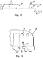
- FIG. 9 is the wiring diagram for the said Piper aircraft.
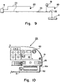
- FIG. 10 is a front view of the control panel of the Piper PA 28 series aircraft.
- FIG. 1 shows an aircraft marked generally as 1 , having a propeller 1 a and an engine compartment marked as 2 .
- an engine compartment front baffle wall 3 a At the front of the engine compartment is an engine compartment front baffle wall 3 a .
- engine baffle wall 3 a In engine baffle wall 3 a is an air intake aperture 4 a .
- ram air is forced through aperture 4 a with movement of the aircraft.
- Permanently attached to engine baffle wall 3 a around aperture 4 a is a flange 5 . This is normally attached to an air duct hose connected to an exhaust muffler shroud (air duct hose not present in FIG. 1 ).
- a blower 6 is attached with L-shaped bracket 7 by means of a bolt, nut and washer 10 to the engine baffle wall 3 a .
- the bracket 7 is attached to the side of the blower by means of a bolt 9 .
- the blower is equipped with a meshed covering 8 to avoid any debris entering the blower.
- a clamp 11 secures a downstream end of the blower 6 to an air duct hose 12 .
- Air duct hose 12 is connected to the inlet hole 31 of a muffler shroud 13 a .
- a muffler shroud is basically an enclosed space or compartment located around the muffler. Warmed air leaves the muffler shroud 13 a via muffler shroud outlet hose 14 which is connected to muffler shroud air outlet 32 .
- warmed air moves through the firewall blower channel 15 and is then directed through cabin heater ducts 16 and defroster duct 17 to defroster nozzle 18 .
- muffler shroud 13 a outlet hose 14 , firewall blower channel 15 , cabin heater duct 16 , defroster duct 17 and defroster nozzle 18 are pre-existing parts of the Cessna 172 aircraft.
- FIG. 2 is a schematic view of the wiring diagram for the invention shown in FIG. 1 .
- a blower indicator light 19 connected to the wiring system. It is mounted on the control panel in the cabin as shown in FIG. 3 .
- the wiring system is grounded at 20 on both the cabin wall and the firewall.
- the blower receives power through the wiring system from the main bus bar or source of electricity in the aircraft.
- the bus bar is marked as 21 .
- the circuit breaker is shown as number 22 . This is connected to the blower circuit breaker switch 25 shown in FIG. 3 .
- Wiring 23 located ahead of the firewall, connects with blower 6 .
- a cabin heat duct control 16 a On the cabin control panel, as shown in FIG. 3 , there is a cabin heat duct control 16 a , a cabin air control 24 , and as previously mentioned, the newly added blower circuit breaker switch 25 .
- Numeral 26 is the flap control; numeral 27 is the avionics indicator; and a numeral 28 is the carburetor temperature indicator.
- the control panel is shown generally as 29 .
- FIG. 3 is a pre-existing control panel of the Cessna 172 model series aircraft and indicates where the new LED light 19 and circuit breaker switch 25 are to be installed.
- FIG. 4 the invention is shown installed in a Cessna 150 aircraft.
- the Cessna 150 there are two mufflers, each with a muffler shroud and two air intakes; hence, two blowers can be used.
- the muffler shrouds are shown in FIG. 4 as 13 a and 13 b .
- the Cessna 150 is also equipped with air scoops 30 located above the apertures on the outside of the front engine compartment baffle wall 3 .
- only one blower 6 is shown connected to flange 5 and firewall 3 by nuts and bolts 10 in FIG.
- blower for each air aperture may be used and one air duct hose 12 leads to air inlet 31 of muffler shroud 13 a while another blower 6 and air duct hose 12 , are connected to an air inlet on muffler shroud 13 b.
- FIG. 5 is a wiring diagram for the blower shown in FIG. 4 . It is similar to FIG. 2 except that when using a 24-volt system, a resistor 33 is placed in the wiring system 23 .
- FIG. 6 shows the existing control panel of the aircraft shown in FIG. 4 . It is understood that FIG. 6 is used simply to show the installed location of the new LED light 19 and the blower on/off switch 25 .
- FIG. 6 shows a mixture control dial 34 , throttle 35 , a vertical speed indicator 36 , an altimeter 37 , a tachometer 38 , an hour and meter 39 , a suction gauge 40 , a left-hand fuel gauge indicator 41 , a right-hand fuel gauge 42 , an oil temp gauge 43 and an oil pressure gauge 44 .
- FIG. 7 is a schematic view of the invention as used in Cessna 180, 182 aircraft.
- FIG. 7 is an illustration which shows that an air intake aperture 4 b need not be in the front engine compartment baffle wall but rather can also be located in the rear engine compartment baffle wall 3 b .
- blower 6 is attached to a flange (not shown) located on rear engine compartment baffle wall 3 b .
- Also shown in FIG. 7 joined to exhaust muffler 13 , are exhaust system inlets 45 and 46 .
- FIG. 8 shows the invention as applied to a Piper PA 28 series aircraft.
- the air intake aperture in this particular aircraft is located in the left-hand forward engine compartment baffle 3 c .
- the Piper PA 28 series is equipped with fresh air inlet knob 47 , a cabin heat shutoff 48 , defroster ducts 49 and defroster control 50 .
- FIG. 9 is the wiring system for blower 6 for the Piper PA 28 series aircraft and is very similar to the wiring systems shown for the previous aircraft.
- FIG. 10 is a front view of the dash 29 for the Piper aircraft, showing in addition, an ammeter 51 and a circuit breaker panel 52 , as well as the other usual controls. Placement of the blower switch 25 and the LED light 19 are indicated.
Landscapes
- Health & Medical Sciences (AREA)
- General Health & Medical Sciences (AREA)
- Pulmonology (AREA)
- Engineering & Computer Science (AREA)
- Aviation & Aerospace Engineering (AREA)
- Air-Conditioning For Vehicles (AREA)
- Structures Of Non-Positive Displacement Pumps (AREA)
- Duct Arrangements (AREA)
Priority Applications (1)
| Application Number | Priority Date | Filing Date | Title |
|---|---|---|---|
| US11/342,452 US20060283968A1 (en) | 2003-06-20 | 2006-01-30 | Blower assisted heating and defogging system for small aircraft |
Applications Claiming Priority (2)
| Application Number | Priority Date | Filing Date | Title |
|---|---|---|---|
| CA2,433,496 | 2003-06-20 | ||
| CA002433496A CA2433496C (fr) | 2003-06-20 | 2003-06-20 | Systeme de chauffage et de desembuage avec ventilateur d'appoint pour petits avions |
Related Child Applications (1)
| Application Number | Title | Priority Date | Filing Date |
|---|---|---|---|
| US11/342,452 Continuation-In-Part US20060283968A1 (en) | 2003-06-20 | 2006-01-30 | Blower assisted heating and defogging system for small aircraft |
Publications (2)
| Publication Number | Publication Date |
|---|---|
| US20040256478A1 US20040256478A1 (en) | 2004-12-23 |
| US7017828B2 true US7017828B2 (en) | 2006-03-28 |
Family
ID=33515057
Family Applications (2)
| Application Number | Title | Priority Date | Filing Date |
|---|---|---|---|
| US10/808,091 Expired - Lifetime US7017828B2 (en) | 2003-06-20 | 2004-03-24 | Blower assisted heating and defogging system for small aircraft |
| US11/342,452 Abandoned US20060283968A1 (en) | 2003-06-20 | 2006-01-30 | Blower assisted heating and defogging system for small aircraft |
Family Applications After (1)
| Application Number | Title | Priority Date | Filing Date |
|---|---|---|---|
| US11/342,452 Abandoned US20060283968A1 (en) | 2003-06-20 | 2006-01-30 | Blower assisted heating and defogging system for small aircraft |
Country Status (2)
| Country | Link |
|---|---|
| US (2) | US7017828B2 (fr) |
| CA (1) | CA2433496C (fr) |
Cited By (2)
| Publication number | Priority date | Publication date | Assignee | Title |
|---|---|---|---|---|
| US20060283968A1 (en) * | 2003-06-20 | 2006-12-21 | Reichle Carl H | Blower assisted heating and defogging system for small aircraft |
| US10647304B2 (en) | 2013-03-14 | 2020-05-12 | Carl Heinz Reichle | Anti-fogging system for single engine aircraft |
Families Citing this family (7)
| Publication number | Priority date | Publication date | Assignee | Title |
|---|---|---|---|---|
| US10215130B2 (en) * | 2012-02-10 | 2019-02-26 | Briggs & Stratton Corporation | Choke override for an engine |
| US9429107B2 (en) | 2013-02-22 | 2016-08-30 | Briggs & Stratton Corporation | Solenoid autochoke for an engine |
| US9945326B2 (en) | 2015-05-07 | 2018-04-17 | Briggs & Stratton Corporation | Automatic choking mechanism for internal combustion engines |
| US9932936B2 (en) | 2015-11-11 | 2018-04-03 | Briggs & Stratton Corporation | Carburetor choke removal mechanism for pressure washers |
| US11059592B2 (en) * | 2016-10-13 | 2021-07-13 | Gulfstream Aerospace Corporation | Coaxial fluid vent and electronic control for a fluid valve for aircraft |
| CN109229339A (zh) * | 2018-08-30 | 2019-01-18 | 哈尔滨飞机工业集团有限责任公司 | 一种直升机动力舱前部整流罩 |
| CN112455646B (zh) * | 2020-11-13 | 2023-07-21 | 中国航空工业集团公司沈阳飞机设计研究所 | 一种对接机构及其除雾结构 |
Citations (7)
| Publication number | Priority date | Publication date | Assignee | Title |
|---|---|---|---|---|
| US2265168A (en) | 1941-06-27 | 1941-12-09 | William E Huffman | Heater, automotive and aircraft |
| US3583658A (en) * | 1969-03-10 | 1971-06-08 | A R A Mfg Co | Single-engine aircraft air-conditioning system |
| US3971511A (en) * | 1975-04-16 | 1976-07-27 | Anthony Joseph Casey | Cabin heater for helicopters and fixed wing aircraft |
| US4490989A (en) | 1982-02-16 | 1985-01-01 | Aero Engineering Corporation | Helicopter heating and air conditioning system |
| US4814579A (en) * | 1986-04-07 | 1989-03-21 | Innovative Scientific Development, Inc. | Electric resistance air reating system for an aircraft cabin |
| US5327744A (en) * | 1992-12-18 | 1994-07-12 | United Technologies Corporation | Integrated environmental control system for a helicopter |
| US6012515A (en) * | 1996-11-27 | 2000-01-11 | Sikorsky Aircraft Corporation | System and method for automatically controlling cabin air temperature in an aircraft |
Family Cites Families (13)
| Publication number | Priority date | Publication date | Assignee | Title |
|---|---|---|---|---|
| US1673149A (en) * | 1927-07-20 | 1928-06-12 | Kohn Ignatius | Portable cooling and heating device for vehicles |
| US1996019A (en) * | 1932-05-16 | 1935-03-26 | Trico Products Corp | Windshield heater |
| US2333818A (en) * | 1940-05-29 | 1943-11-09 | Ranco Inc | Heating system |
| US2523923A (en) * | 1946-06-22 | 1950-09-26 | Stewart Warner Corp | Automobile heating system |
| US2876998A (en) * | 1956-10-18 | 1959-03-10 | Ford Motor Co | Heater air conditioning ductwork |
| US3096938A (en) * | 1960-09-02 | 1963-07-09 | Gen Motors Corp | Heating and ventilating system for air cooled engine cars |
| US3278121A (en) * | 1963-09-26 | 1966-10-11 | Porsche Kg | Vehicle heating system |
| US3908900A (en) * | 1974-04-29 | 1975-09-30 | James R Smith | Recirculating automotive heating system |
| US5114382A (en) * | 1987-11-23 | 1992-05-19 | Air Comm Corporation | Windshield defrosting apparatus and method for aircraft |
| US5632673A (en) * | 1995-10-30 | 1997-05-27 | Chrysler Corporation | Ventilation system for lightweight automobile |
| FR2775221B1 (fr) * | 1998-02-20 | 2000-05-26 | Renault | Dispositif d'aeration, de chauffage et de climatisation d'un habitacle d'un vehicule automobile |
| US5987216A (en) * | 1998-04-27 | 1999-11-16 | Krug; Schani | Defrosting, deicing, and heating device |
| CA2433496C (fr) * | 2003-06-20 | 2008-12-09 | Heinz Reichle | Systeme de chauffage et de desembuage avec ventilateur d'appoint pour petits avions |
-
2003
- 2003-06-20 CA CA002433496A patent/CA2433496C/fr not_active Expired - Fee Related
-
2004
- 2004-03-24 US US10/808,091 patent/US7017828B2/en not_active Expired - Lifetime
-
2006
- 2006-01-30 US US11/342,452 patent/US20060283968A1/en not_active Abandoned
Patent Citations (7)
| Publication number | Priority date | Publication date | Assignee | Title |
|---|---|---|---|---|
| US2265168A (en) | 1941-06-27 | 1941-12-09 | William E Huffman | Heater, automotive and aircraft |
| US3583658A (en) * | 1969-03-10 | 1971-06-08 | A R A Mfg Co | Single-engine aircraft air-conditioning system |
| US3971511A (en) * | 1975-04-16 | 1976-07-27 | Anthony Joseph Casey | Cabin heater for helicopters and fixed wing aircraft |
| US4490989A (en) | 1982-02-16 | 1985-01-01 | Aero Engineering Corporation | Helicopter heating and air conditioning system |
| US4814579A (en) * | 1986-04-07 | 1989-03-21 | Innovative Scientific Development, Inc. | Electric resistance air reating system for an aircraft cabin |
| US5327744A (en) * | 1992-12-18 | 1994-07-12 | United Technologies Corporation | Integrated environmental control system for a helicopter |
| US6012515A (en) * | 1996-11-27 | 2000-01-11 | Sikorsky Aircraft Corporation | System and method for automatically controlling cabin air temperature in an aircraft |
Cited By (2)
| Publication number | Priority date | Publication date | Assignee | Title |
|---|---|---|---|---|
| US20060283968A1 (en) * | 2003-06-20 | 2006-12-21 | Reichle Carl H | Blower assisted heating and defogging system for small aircraft |
| US10647304B2 (en) | 2013-03-14 | 2020-05-12 | Carl Heinz Reichle | Anti-fogging system for single engine aircraft |
Also Published As
| Publication number | Publication date |
|---|---|
| US20060283968A1 (en) | 2006-12-21 |
| CA2433496A1 (fr) | 2004-12-20 |
| CA2433496C (fr) | 2008-12-09 |
| US20040256478A1 (en) | 2004-12-23 |
Similar Documents
| Publication | Publication Date | Title |
|---|---|---|
| EP1405986B1 (fr) | Dispositif anti-givrage pour une surface interne d'un turboréacteur d'avion | |
| US6216981B1 (en) | Environmental control system | |
| US6282881B1 (en) | Cooling system for a turbomachine speed reducer | |
| CA2950782C (fr) | Systeme de gestion thermique | |
| EP2250090B1 (fr) | Protection antigivre pour buses d admission d air d aéronef | |
| US2164545A (en) | Airplane | |
| EP3385510B1 (fr) | Procédé pour faire fonctionner un prérefroidisseur dans un aéronef et moteur aéronef | |
| US7017828B2 (en) | Blower assisted heating and defogging system for small aircraft | |
| US4976397A (en) | Anti-icing system for aircraft | |
| EP0035909A2 (fr) | Système de conditionnement d'air | |
| EP1069044A2 (fr) | Source d'energie et de poussee auxiliaire | |
| US3109610A (en) | Combined aircraft air intake scoop, foreign material ingestion inhibitor, and aerodynamic flap | |
| US4465154A (en) | Vehicle gas extractor | |
| EP2835517B1 (fr) | Système empêcher l'accumulation de cristaux de glace dans des moteurs à turbine à gaz | |
| US20240301826A1 (en) | Aircraft turboprop engine inlet compact profile configuration | |
| US5852846A (en) | Windshield airstream deflector for vehicles | |
| US5617608A (en) | Windshield protection and cleaning system | |
| US3583658A (en) | Single-engine aircraft air-conditioning system | |
| US2898745A (en) | Automobile air conditioning and supercharging system | |
| US2647366A (en) | Means for preventing ice formation in jet propulsion and gas turbine engines | |
| US20020162345A1 (en) | System for supplying an aircraft with cool air | |
| US3416428A (en) | Defroster and windshield heater | |
| US2869535A (en) | Aircraft heating system | |
| US5014606A (en) | Windshield defroster system for the Bell Helicopter Textron, Inc., model 206 helicopter and military derivatives | |
| US10647304B2 (en) | Anti-fogging system for single engine aircraft |
Legal Events
| Date | Code | Title | Description |
|---|---|---|---|
| STCF | Information on status: patent grant |
Free format text: PATENTED CASE |
|
| FPAY | Fee payment |
Year of fee payment: 4 |
|
| FPAY | Fee payment |
Year of fee payment: 8 |
|
| MAFP | Maintenance fee payment |
Free format text: PAYMENT OF MAINTENANCE FEE, 12TH YR, SMALL ENTITY (ORIGINAL EVENT CODE: M2553) Year of fee payment: 12 |