US7032471B2 - Control device for controlling machines by hand or foot - Google Patents
Control device for controlling machines by hand or foot Download PDFInfo
- Publication number
- US7032471B2 US7032471B2 US10/149,408 US14940802A US7032471B2 US 7032471 B2 US7032471 B2 US 7032471B2 US 14940802 A US14940802 A US 14940802A US 7032471 B2 US7032471 B2 US 7032471B2
- Authority
- US
- United States
- Prior art keywords
- fluid
- operating element
- movement
- cavity
- accumulator
- Prior art date
- Legal status (The legal status is an assumption and is not a legal conclusion. Google has not performed a legal analysis and makes no representation as to the accuracy of the status listed.)
- Expired - Lifetime
Links
- 239000012530 fluid Substances 0.000 claims abstract description 64
- 238000013016 damping Methods 0.000 claims abstract description 36
- 230000005540 biological transmission Effects 0.000 claims description 13
- 230000000284 resting effect Effects 0.000 claims description 13
- 239000011553 magnetic fluid Substances 0.000 claims description 4
- 230000003287 optical effect Effects 0.000 claims description 2
- 238000006073 displacement reaction Methods 0.000 claims 1
- 230000008901 benefit Effects 0.000 description 4
- 230000001419 dependent effect Effects 0.000 description 4
- 238000006243 chemical reaction Methods 0.000 description 3
- 230000009471 action Effects 0.000 description 2
- 230000006835 compression Effects 0.000 description 2
- 238000007906 compression Methods 0.000 description 2
- 230000000881 depressing effect Effects 0.000 description 2
- 230000009467 reduction Effects 0.000 description 2
- 230000008859 change Effects 0.000 description 1
- 230000001276 controlling effect Effects 0.000 description 1
- 230000008878 coupling Effects 0.000 description 1
- 238000010168 coupling process Methods 0.000 description 1
- 238000005859 coupling reaction Methods 0.000 description 1
- 230000005611 electricity Effects 0.000 description 1
- 230000014759 maintenance of location Effects 0.000 description 1
- 230000001105 regulatory effect Effects 0.000 description 1
- 238000009877 rendering Methods 0.000 description 1
- 230000035945 sensitivity Effects 0.000 description 1
- 238000004513 sizing Methods 0.000 description 1
Images


Classifications
-
- G—PHYSICS
- G05—CONTROLLING; REGULATING
- G05G—CONTROL DEVICES OR SYSTEMS INSOFAR AS CHARACTERISED BY MECHANICAL FEATURES ONLY
- G05G1/00—Controlling members, e.g. knobs or handles; Assemblies or arrangements thereof; Indicating position of controlling members
- G05G1/30—Controlling members actuated by foot
-
- B—PERFORMING OPERATIONS; TRANSPORTING
- B66—HOISTING; LIFTING; HAULING
- B66F—HOISTING, LIFTING, HAULING OR PUSHING, NOT OTHERWISE PROVIDED FOR, e.g. DEVICES WHICH APPLY A LIFTING OR PUSHING FORCE DIRECTLY TO THE SURFACE OF A LOAD
- B66F9/00—Devices for lifting or lowering bulky or heavy goods for loading or unloading purposes
- B66F9/06—Devices for lifting or lowering bulky or heavy goods for loading or unloading purposes movable, with their loads, on wheels or the like, e.g. fork-lift trucks
- B66F9/075—Constructional features or details
- B66F9/20—Means for actuating or controlling masts, platforms, or forks
-
- E—FIXED CONSTRUCTIONS
- E02—HYDRAULIC ENGINEERING; FOUNDATIONS; SOIL SHIFTING
- E02F—DREDGING; SOIL-SHIFTING
- E02F9/00—Component parts of dredgers or soil-shifting machines, not restricted to one of the kinds covered by groups E02F3/00 - E02F7/00
- E02F9/20—Drives; Control devices
- E02F9/2004—Control mechanisms, e.g. control levers
-
- E—FIXED CONSTRUCTIONS
- E02—HYDRAULIC ENGINEERING; FOUNDATIONS; SOIL SHIFTING
- E02F—DREDGING; SOIL-SHIFTING
- E02F9/00—Component parts of dredgers or soil-shifting machines, not restricted to one of the kinds covered by groups E02F3/00 - E02F7/00
- E02F9/20—Drives; Control devices
- E02F9/22—Hydraulic or pneumatic drives
- E02F9/2203—Arrangements for controlling the attitude of actuators, e.g. speed, floating function
- E02F9/2207—Arrangements for controlling the attitude of actuators, e.g. speed, floating function for reducing or compensating oscillations
-
- E—FIXED CONSTRUCTIONS
- E02—HYDRAULIC ENGINEERING; FOUNDATIONS; SOIL SHIFTING
- E02F—DREDGING; SOIL-SHIFTING
- E02F9/00—Component parts of dredgers or soil-shifting machines, not restricted to one of the kinds covered by groups E02F3/00 - E02F7/00
- E02F9/20—Drives; Control devices
- E02F9/22—Hydraulic or pneumatic drives
- E02F9/2217—Hydraulic or pneumatic drives with energy recovery arrangements, e.g. using accumulators, flywheels
-
- F—MECHANICAL ENGINEERING; LIGHTING; HEATING; WEAPONS; BLASTING
- F15—FLUID-PRESSURE ACTUATORS; HYDRAULICS OR PNEUMATICS IN GENERAL
- F15B—SYSTEMS ACTING BY MEANS OF FLUIDS IN GENERAL; FLUID-PRESSURE ACTUATORS, e.g. SERVOMOTORS; DETAILS OF FLUID-PRESSURE SYSTEMS, NOT OTHERWISE PROVIDED FOR
- F15B13/00—Details of servomotor systems ; Valves for servomotor systems
- F15B13/14—Special measures for giving the operating person a "feeling" of the response of the actuated device
-
- G—PHYSICS
- G05—CONTROLLING; REGULATING
- G05G—CONTROL DEVICES OR SYSTEMS INSOFAR AS CHARACTERISED BY MECHANICAL FEATURES ONLY
- G05G9/00—Manually-actuated control mechanisms provided with one single controlling member co-operating with two or more controlled members, e.g. selectively, simultaneously
- G05G9/02—Manually-actuated control mechanisms provided with one single controlling member co-operating with two or more controlled members, e.g. selectively, simultaneously the controlling member being movable in different independent ways, movement in each individual way actuating one controlled member only
- G05G9/04—Manually-actuated control mechanisms provided with one single controlling member co-operating with two or more controlled members, e.g. selectively, simultaneously the controlling member being movable in different independent ways, movement in each individual way actuating one controlled member only in which movement in two or more ways can occur simultaneously
- G05G9/047—Manually-actuated control mechanisms provided with one single controlling member co-operating with two or more controlled members, e.g. selectively, simultaneously the controlling member being movable in different independent ways, movement in each individual way actuating one controlled member only in which movement in two or more ways can occur simultaneously the controlling member being movable by hand about orthogonal axes, e.g. joysticks
-
- Y—GENERAL TAGGING OF NEW TECHNOLOGICAL DEVELOPMENTS; GENERAL TAGGING OF CROSS-SECTIONAL TECHNOLOGIES SPANNING OVER SEVERAL SECTIONS OF THE IPC; TECHNICAL SUBJECTS COVERED BY FORMER USPC CROSS-REFERENCE ART COLLECTIONS [XRACs] AND DIGESTS
- Y10—TECHNICAL SUBJECTS COVERED BY FORMER USPC
- Y10T—TECHNICAL SUBJECTS COVERED BY FORMER US CLASSIFICATION
- Y10T74/00—Machine element or mechanism
- Y10T74/20—Control lever and linkage systems
- Y10T74/20012—Multiple controlled elements
- Y10T74/20189—Foot operated
-
- Y—GENERAL TAGGING OF NEW TECHNOLOGICAL DEVELOPMENTS; GENERAL TAGGING OF CROSS-SECTIONAL TECHNOLOGIES SPANNING OVER SEVERAL SECTIONS OF THE IPC; TECHNICAL SUBJECTS COVERED BY FORMER USPC CROSS-REFERENCE ART COLLECTIONS [XRACs] AND DIGESTS
- Y10—TECHNICAL SUBJECTS COVERED BY FORMER USPC
- Y10T—TECHNICAL SUBJECTS COVERED BY FORMER US CLASSIFICATION
- Y10T74/00—Machine element or mechanism
- Y10T74/20—Control lever and linkage systems
- Y10T74/20396—Hand operated
-
- Y—GENERAL TAGGING OF NEW TECHNOLOGICAL DEVELOPMENTS; GENERAL TAGGING OF CROSS-SECTIONAL TECHNOLOGIES SPANNING OVER SEVERAL SECTIONS OF THE IPC; TECHNICAL SUBJECTS COVERED BY FORMER USPC CROSS-REFERENCE ART COLLECTIONS [XRACs] AND DIGESTS
- Y10—TECHNICAL SUBJECTS COVERED BY FORMER USPC
- Y10T—TECHNICAL SUBJECTS COVERED BY FORMER US CLASSIFICATION
- Y10T74/00—Machine element or mechanism
- Y10T74/20—Control lever and linkage systems
- Y10T74/20528—Foot operated
Definitions
- the invention relates to a control device for the manual or foot-operated control of machines with the features of the preamble of claim 1 .
- Machines with hydraulic drives such as, e.g., diggers or front loaders, are often controlled by control levers and pedals, which operate via slide and valve systems directly on the hydraulic circuit. Through the reaction of the hydraulic fluid, these control elements or operating elements put up a certain resistance to the hand or foot when operated.
- Each lever can hereby be moved in at least two directions, e.g., forwards and backwards.
- This power of resistance serves the operator of the machine as feedback for the actions he takes, thus rendering possible an easier execution of the movements of the machine.
- a control system e.g., a control computer
- the movement of the respective control element via intermediate parts e.g., electrical slide resistance or rheostats
- a signal e.g., an electrical analog or digital signal.
- the resistance that the machine operator feels when operating an operating element is often determined only by a return spring and essentially depends on the mechanical sensitivity of the sensor.
- a control device of the type mentioned at the outset is known from DE 36 22 260 A1.
- the operation of a control lever is damped by a damping device that features a piston that is moveable in a cylinder and separates two cylinder chambers from one another.
- the two cylinder chambers are connected by a bypass channel arrangement.
- a choke is arranged in a bypass channel of this arrangement.
- Prestressed back-pressure valves connected in counter-parallel are arranged in the two other bypass channels of this arrangement.
- EP 0 899 147 A1 shows a driving pedal with damping device, in which a damping is caused by a piston which can be displaced in a cylinder.
- a choke and a back-pressure valve are arranged in the piston.
- the choke puts up an increased resistance to a movement of the piston in one direction, whereas the back-pressure valve permits a movement in the other direction with a reduced resistance.
- a spring is arranged parallel to the piston.
- EP 0 331 177 A1 shows a control device with an active system for the targeted impingement of an operating element.
- the operating element features a damping piston for each direction of operation, which damping piston rests on the operating element with an extension prolongation.
- the other side of the piston is impinged with pressure by the hydraulic system, whereby the pressure can be adjusted through a pressure adjustment valve, specifically depending on the operating pressures in the system and a load acting on the system.
- the object of the invention is to provide a control device for the manual or foot-operated control of machines, in which a power of resistance can be felt during shifting or adjusting the operating element, which power of resistance is in the order of magnitude of conventional machines.
- the reduction of the fluid-filled cavity is a relatively simple possibility for building up a high resistance with the aid of a moved fluid.
- the flow-off speed of the fluid is a gauge of how quickly the cavity can be reduced.
- the reduction speed of the cavity is a gauge of how quickly the operating element can be moved.
- the cavity is formed in a cylinder and is partially limited by a piston that is displaceable in the cylinder, whereby under the pressure of the fluid the piston rests against the operating element or a driving device connected to it, the piston is kept against the operating element during the entire operation of the operating element and thus puts up the corresponding resistance to the operating element upon movement in the corresponding direction.
- the piston interacts with a limit stop which is adjusted to the resting position of the operating element. This is particularly advantageous if the operating element can be moved in two opposite directions. The power of resistance during movement in one direction is then not masked by a corresponding elastic force in the other direction.
- Each damping device thus always acts only in one direction, putting up a corresponding resistance to the movement in this direction, whereas the movement of the operating element in the other direction remains uninfluenced by this damping device.
- a certain pressure difference has to be available via the choke, which pressure difference is generated by the operator building up the appropriate pressure in the cavity via the operating element.
- the flow-off behavior of the fluid from the cavity can be selectively controlled by the choice of the size of the choke.
- the flow-off stop valve thus opens for the fluid that wants to flow back from the outlet into the cavity.
- the fluid is thus practically unhindered from flowing back into the cavity, whereas the fluid can flow out of the cavity only through the choke.
- This embodiment has the advantage on the one hand that hardly any force is needed to reset the operating element.
- it has the advantage that a pressure can be used at the outlet in order to convey the fluid back into the cavity.
- the damping device preferably puts up a basic resistance to a movement of the operating element from its resting position.
- This embodiment has several advantages. For one thing, the operator receives a corresponding resistance from the start of the movement, which resistance does not have to build up in the course of the movement. For another, it is ensured that the operating element can only be moved from a resting position when the operator actually intends to move it. Accidental movements, which can be caused by a vibration of the machine or by other outside influences, can be avoided with a relatively high reliability.
- the damping device preferably puts up a reduced resistance to a movement of the operating element from a deflected position into its resting position.
- This resistance can be practically nothing at all.
- the operating element can return to its resting position quickly and without larger outside forces, whereas it requires greater forces to deflect the operating element from its resting position.
- This is linked, i.a., with a safety aspect. When the operator is no longer influencing it, the operating element is then automatically returned to its resting position, so that movements of the machine caused by shifting the operating element also cease.
- the fluid is preferably under pressure.
- the defined basic resistance to the movement of the operating element is thus already generated at the start of the movement of the operating element.
- the outlet of the cavity is preferably connected to an accumulator.
- the pressure of the fluid is accordingly defined in the accumulator so that the necessary basic resistance can already be generated at the start of the movement of the operating element.
- the level of the pressure in the accumulator is a gauge of this basic resistance.
- the accumulator prefferably contains a gas bubble.
- a certain spring characteristic can be achieved with the aid of this gas bubble, i.e., the pressure increases with increasing deflection or shifting of the operating element.
- the fluid is namely displaced in the accumulator such that it compresses the gas bubble.
- the gas bubble thereby generates a counterpressure dependent on the degree of compression, which counterpressure increases with the increasing degree of compression.
- the fluid is preferably a hydraulic fluid. Hydraulic fluid is available in sufficient quantity with most hydraulic machines. The supply does not require additional expense.
- the fluid features a viscosity which can be altered by the action of a control component.
- This viscosity is one of the values with which the flow-off behavior of a fluid can be changed. If the viscosity is altered, the flow-off speed is altered as well.
- the fluid is preferably a magnetic fluid.
- a magnetic fluid changes its viscosity or its flow behavior when it is exposed to a magnetic field.
- a magnetic field can be generated by a magnet, e.g., an electromagnet, in order to change the flow-off speed.
- the fluid is a compressed gas.
- the appropriate damping can also be caused by a gas.
- the choke is preferably adjustable.
- the resistance behavior can be adapted to the requirements of a special vehicle or a special operator.
- the operating element is preferably a pedal which can be pivoted about an axis or a rocker lever. These are the most common control devices which can be controlled well with the damping device.
- the operating element is also preferred for the operating element to be a universal-mounted control lever which features a driver ring surrounding it at right angles to its longitudinal extension near the universal mounting, which driver ring rests on the piston in the resting position. A damping thus occurs in virtually every movement direction.
- a different resistance is assigned to a first pair of movement directions than to a second pair of movement directions which is perpendicular to the first pair of movement directions. It is thus possible, e.g., to put up a stronger resistance to lateral movements than to lengthwise movements, in order to give the machine operator a feeling for the exact guidance in a forwards-backwards direction.
- FIG. 1 A control device with a simple-action pedal
- FIG. 2 A control device with a pedal embodied as a rocker lever
- FIG. 3 A control device with an operating element in the form of a control lever with a choke-valve combination
- FIG. 4 A control device with an operating element in the form of a control lever with several choke-valve combinations and a choke control dependent on a work circuit.
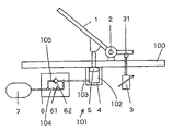
- FIG. 1 shows an embodiment of a control device with a simple pedal. This embodiment is intended to show the fundamental idea of the invention.
- An operating element 1 in the form of a pedal supported on a baseplate 100 in a bearing 2 is connected to a transmission device 3 via a coupling device 31 .
- the transmission device 3 generates a signal in a way that is not shown, but known per se, with a movement of the operating element 1 , which signal is converted into hydraulic pressures via a processing unit (not shown in detail), e.g., a control computer.
- a processing unit e.g., a control computer.
- the control computer operates, e.g., predetermined valves in the hydraulic circuit of a machine, e.g., a digger or a loader.
- the signals emitted by the transmission device 3 are usually in electrical form, whereby they can be analog or digital. However, it is also possible for the transmission device 3 to generate pneumatic, optical or hydraulic signals, whereby in the latter case the signal path is uncoupled from the hydraulic work circuit.
- a damping device 101 is arranged in the operating direction of the control element 1 embodied as a pedal.
- the damping device features a cylinder 4 in which a piston 5 is displaceably guided between two end positions.
- the piston 5 is thereby arranged such that in the starting position of the pedal it is located in its upper end position. This end position is defined by the impact of the piston on the base plate 100 . It is not possible to move the piston 5 beyond this end position.
- a cavity 102 is formed in the cylinder 4 , which cavity is limited by the cylinder 4 and the piston 5 .
- the cavity 102 is filled with a hydraulic fluid.
- the hydraulic fluid is displaced outwards via an outlet 103 and reaches an accumulator 7 via a damping element 6 .
- the damping element 6 contains in an outflow path 104 a choke 61 which forms a device for controlling the flow-off speed of the hydraulic fluid.
- the choke resistance of the choke 61 can be adjusted if necessary, as indicated by an arrow.
- An inflow path 105 is arranged parallel to the outflow path 104 .
- a valve 62 is provided in the inflow path 105 , which valve is embodied as a back-pressure valve.
- the valve 62 opens into the cavity 102 and closes in the direction of the accumulator 7 .
- a predetermined pressure prevails in the accumulator 7 . This pressure prevails when the piston 5 is in its upper end position, also in the cavity 102 .
- a certain basic resistance of the operating element 1 is thus set by the pressure available in the accumulator 7 .
- a gas bubble can be contained in the accumulator 7 , the size of which gas bubble is adjusted to the volume of the cavity 102 in the cylinder 4 . With appropriate sizing the counterpressure in the accumulator 7 can increase upon the deflection of the operating element 1 . The machine operator thus receives a feedback on the degree of operation of the operating element 7 .
- the adjustment of the choke 61 causes a higher resistance to be opposed to a rapid depressing of the pedal than is the case with a slow depressing of the pedal. This rules out above all the transfer of jerky movements or vibrations of the machine to the transmission device 3 via the pedal.
- the resistance against the movement of the operating element 1 is only built up by movements in one direction, i.e., the movement of the operating element 1 from its resting position.
- the choke device 6 produces basically no resistance.
- the hydraulic fluid is conveyed back into the cavity 102 by the pressure in the accumulator 7 via the valve 62 which then opens, so that the piston 5 can directly follow the movement of the operating element 1 .
- FIG. 2 shows another exemplary embodiment, in which the operating element 1 is embodied as a pedal operating in a two-sided manner, i.e., as a rocker lever.
- the same elements are given the same reference number.
- Cylinder 4 and piston 5 which enclose a cavity 102 , are provided for both movement directions here.
- Each piston-cylinder-unit operates only when the operating element 1 is moved from the resting position shown in FIG. 2 . No resistance is opposed to a movement of the operating element 1 from a deflected position back into the resting position. The precise adjustment of the normal position when releasing the pedal is ensured by the upper end stops of the piston 5 which is formed by the baseplate 100 .
- the damping occurs by a hydraulic fluid being displaced by the chokes 61 when the cavities 102 are reduced.
- a gas it is just as possible for a gas to be used instead of a hydraulic fluid.
- the choke 61 will have to be sized differently.
- FIG. 3 shows an embodiment of the control device, in which the operating element is embodied as a control lever or joystick. Only one pair of movement directions is shown for reasons of clarity, i.e., from left to right and from right to left. The same parts are given the same reference numbers.
- a piston 5 is provided in the cylinders 4 for each movement direction, whereby the outlets of both cavities 102 thus formed are connected to a joint damping element 6 , which is structured identically to the exemplary embodiment of FIG. 1 .
- the operating element 1 can also be suspended on gimbals, whereby only one axis is shown, as mentioned above.
- the basic pressure in the cavities 102 of the cylinders 4 is derived from the control circuit 71 of the hydraulic pump.
- FIG. 4 shows another exemplary embodiment which shows that only the piston 5 located in the movement direction is pushed into the cylinder 4 , in order to reduce the cavity 102 arranged therein.
- each cylinder 4 is assigned a damping element 6 featuring a choke 61 and a valve 62 .
- a varying counter force can thus be assigned to different movement directions on the movement of the operating element. For instance, a forward movement can be assigned a greater counter force than a backward movement.
- such an embodiment is designed in principle so that several pairs of movement directions are available, whereby the pairs of movement directions are aligned perpendicular to one another. In this case, a greater resistance force can be opposed to a lateral movement than to a forward-backward movement, so that it is possible to give the machine operator a feeling for the exact guidance in the forward-backward direction.
- FIG. 4 also shows in a diagrammatic representation that the chokes 61 can be controlled with a control pressure that is derived via a pressure transducer 73 out of the work circuit 72 of the hydraulic machine.
- the damping i.e., the resistance force opposed to the movement, automatically increases with the increase in the strain on the machine, which in most cases is also accompanied by increased vibrations of the system.
- the pressure of the work circuit 72 transformed via a pressure transducer 73 can also be used to adjust the working pressure in the cavity 102 in the cylinders 4 .
- the machine operator is thus given a feedback on particular pressures of the machine. For instance, the pressure in cylinder 4 can be increased so much when the digger bucket comes across an obstacle that when the load limit is reached only a retraction of the lever is possible, so that a deliberate overload of the machine can be prevented.
- the damping occurs by a hydraulic fluid being displaced by the chokes 61 when the cavities 102 are reduced.
- a gas it is just as possible for a gas to be used instead of a hydraulic fluid.
- the choke 61 will have to be sized differently.
- the viscosity of the fluid can be changed by arranging an electromagnet in the outflow path and impinging the electromagnet (not shown) with electricity. If the viscosity is changed, the outflow behavior is changed, i.e., a more viscous fluid is braked more by the choke 61 than a thinner fluid.
Landscapes
- Engineering & Computer Science (AREA)
- Structural Engineering (AREA)
- Civil Engineering (AREA)
- General Engineering & Computer Science (AREA)
- Mining & Mineral Resources (AREA)
- Physics & Mathematics (AREA)
- Transportation (AREA)
- Mechanical Engineering (AREA)
- General Physics & Mathematics (AREA)
- Automation & Control Theory (AREA)
- Chemical & Material Sciences (AREA)
- Combustion & Propulsion (AREA)
- Fluid Mechanics (AREA)
- Life Sciences & Earth Sciences (AREA)
- Geology (AREA)
- Operation Control Of Excavators (AREA)
- Mechanical Control Devices (AREA)
- Selective Calling Equipment (AREA)
- Telephone Function (AREA)
- Transplanting Machines (AREA)
- Harvester Elements (AREA)
- Lifting Devices For Agricultural Implements (AREA)
- Fluid-Pressure Circuits (AREA)
Applications Claiming Priority (5)
| Application Number | Priority Date | Filing Date | Title |
|---|---|---|---|
| DE29921943U DE29921943U1 (de) | 1999-12-16 | 1999-12-16 | Steuervorrichtung für die manuell- oder fußgeführte Steuerung von Arbeitsmaschinen |
| DE19961052.5 | 1999-12-16 | ||
| DE29921943.7 | 1999-12-16 | ||
| DE19961052A DE19961052A1 (de) | 1999-12-16 | 1999-12-22 | Steuervorrichtung für die manuell- oder fußgeführte Steuerung von Arbeitsmaschinen |
| PCT/EP2000/012644 WO2001044668A2 (de) | 1999-12-16 | 2000-12-13 | Steuervorrichtung für die manuell- oder fussgeführte steuerung von arbeitsmaschinen |
Publications (2)
| Publication Number | Publication Date |
|---|---|
| US20020178854A1 US20020178854A1 (en) | 2002-12-05 |
| US7032471B2 true US7032471B2 (en) | 2006-04-25 |
Family
ID=26055834
Family Applications (1)
| Application Number | Title | Priority Date | Filing Date |
|---|---|---|---|
| US10/149,408 Expired - Lifetime US7032471B2 (en) | 1999-12-16 | 2000-12-13 | Control device for controlling machines by hand or foot |
Country Status (7)
| Country | Link |
|---|---|
| US (1) | US7032471B2 (de) |
| EP (1) | EP1276995B1 (de) |
| AT (1) | ATE296961T1 (de) |
| AU (1) | AU3363501A (de) |
| DE (2) | DE19961052A1 (de) |
| ES (1) | ES2240235T3 (de) |
| WO (1) | WO2001044668A2 (de) |
Cited By (5)
| Publication number | Priority date | Publication date | Assignee | Title |
|---|---|---|---|---|
| US20110214751A1 (en) * | 2008-11-12 | 2011-09-08 | Bosch Rexroth D.S.I. | Pressure regulator device, especially of the hydraulic remote-control type |
| US20160004271A1 (en) * | 2014-07-01 | 2016-01-07 | Raytheon BBN Technologies, Corp. | Accelerator Pedal Assembly |
| US10353422B2 (en) * | 2015-06-23 | 2019-07-16 | Kongsberg Power Products Systems I, Inc. | Bidirectional pedal assembly |
| US11180900B2 (en) * | 2017-03-31 | 2021-11-23 | Hitachi Construction Machinery Co., Ltd. | Construction machine |
| US20230018708A1 (en) * | 2020-04-22 | 2023-01-19 | Ningbo Geely Automobile Research & Development Co., Ltd. | Pedal system for road and flight operational use vehicle |
Families Citing this family (10)
| Publication number | Priority date | Publication date | Assignee | Title |
|---|---|---|---|---|
| DE19939796C1 (de) | 1999-08-21 | 2000-11-23 | Orenstein & Koppel Ag | Verfahren und Arbeitsmaschine zur Herstellung von Bodenflächen |
| DE10133492A1 (de) * | 2001-07-10 | 2003-01-30 | Itt Mfg Enterprises Inc | Fuß-oder handbetätigbares Steuerungsmodul |
| JP4772464B2 (ja) * | 2005-11-11 | 2011-09-14 | オリンパスメディカルシステムズ株式会社 | 操作装置 |
| DE102006042629A1 (de) * | 2006-09-05 | 2008-03-20 | ITT Mfg. Enterprises, Inc., Wilmington | Schaltknüppel |
| EP3088263B1 (de) * | 2015-04-28 | 2017-12-20 | Bitron S.p.A. | Pedalsteuerungsvorrichtung, insbesondere für ein motorfahrzeug |
| FR3054049B1 (fr) * | 2016-07-12 | 2019-05-31 | Robert Bosch Gmbh | Telecommande d'engin equipee d'un amortisseur |
| JP6704841B2 (ja) * | 2016-12-01 | 2020-06-03 | 株式会社日立建機ティエラ | 小型油圧ショベル |
| CN110337628B (zh) * | 2017-03-03 | 2021-02-02 | 威廉姆斯控制有限公司 | 电子控制器组件中的非液压集成阻尼机构 |
| JP7708523B2 (ja) * | 2023-06-07 | 2025-07-15 | 三菱ロジスネクスト株式会社 | フォークリフト、ペダル重さ変更システムおよびペダル重さ推定プログラム |
| JP7693267B2 (ja) * | 2023-06-26 | 2025-06-17 | 三菱ロジスネクスト株式会社 | フォークリフト、ペダル重さ変更システム、ペダル重さ推定プログラムおよびフォークリフト割当システム |
Citations (14)
| Publication number | Priority date | Publication date | Assignee | Title |
|---|---|---|---|---|
| US2754505A (en) * | 1953-10-21 | 1956-07-10 | Tactair Inc | Tactile control indicator |
| US3978738A (en) * | 1973-12-26 | 1976-09-07 | La Telemecanique Electrique | Toggle manipulator |
| US4012014A (en) * | 1975-09-11 | 1977-03-15 | Mcdonnell Douglas Corporation | Aircraft flight controller |
| US4530376A (en) * | 1983-09-19 | 1985-07-23 | Dresser Industries, Inc. | Pilot valve including a hydraulically actuated detent |
| DE3622260A1 (de) | 1985-07-18 | 1987-01-29 | Volkswagen Ag | Kraftfahrzeug-antriebsaggregat mit einem mehrgaengigen automatikgetriebe |
| EP0331177A1 (de) | 1988-03-03 | 1989-09-06 | KABUSHIKI KAISHA KOBE SEIKO SHO also known as Kobe Steel Ltd. | Vorrichtung zur Beherrschung der Arbeitsreaktion einer Winde |
| US5156065A (en) * | 1988-11-11 | 1992-10-20 | Kabushiki Kaisha Kobe Seiko Sho | Control lever apparatus and actuator operation apparatus |
| JPH05112215A (ja) * | 1991-10-22 | 1993-05-07 | Toyota Autom Loom Works Ltd | 車両用ブレーキペダル装置 |
| US5289902A (en) * | 1991-10-29 | 1994-03-01 | Kabushiki Kaisha Toshiba | Elevator |
| US5452745A (en) * | 1992-11-06 | 1995-09-26 | Byelocorp Scientific, Inc. | Magnetorheological valve and devices incorporating magnetorheological elements |
| US5558127A (en) * | 1992-10-09 | 1996-09-24 | Kabushiki Kaisha Komatsu Seisakusho | Hydraulic pilot valve |
| US5576704A (en) * | 1994-12-01 | 1996-11-19 | Caterpillar Inc. | Capacitive joystick apparatus |
| EP0889147A1 (de) | 1996-02-29 | 1999-01-07 | Nippon Steel Corporation | Verfahren zur zinnplattierung und bad mit weitem optimalen stromdichtebereich |
| US6029537A (en) * | 1997-05-08 | 2000-02-29 | Konami Co., Ltd. | Multi directional shift mechanism |
Family Cites Families (2)
| Publication number | Priority date | Publication date | Assignee | Title |
|---|---|---|---|---|
| DE19737289A1 (de) * | 1997-08-27 | 1999-03-04 | Mannesmann Vdo Ag | Steuereinrichtung |
| DE29921943U1 (de) * | 1999-12-16 | 2000-07-27 | Tyroller Hydraulik Herzberg GmbH, 04916 Herzberg | Steuervorrichtung für die manuell- oder fußgeführte Steuerung von Arbeitsmaschinen |
-
1999
- 1999-12-22 DE DE19961052A patent/DE19961052A1/de not_active Withdrawn
-
2000
- 2000-12-13 AU AU33635/01A patent/AU3363501A/en not_active Abandoned
- 2000-12-13 ES ES00991594T patent/ES2240235T3/es not_active Expired - Lifetime
- 2000-12-13 WO PCT/EP2000/012644 patent/WO2001044668A2/de not_active Ceased
- 2000-12-13 EP EP00991594A patent/EP1276995B1/de not_active Expired - Lifetime
- 2000-12-13 DE DE50010480T patent/DE50010480D1/de not_active Expired - Lifetime
- 2000-12-13 AT AT00991594T patent/ATE296961T1/de not_active IP Right Cessation
- 2000-12-13 US US10/149,408 patent/US7032471B2/en not_active Expired - Lifetime
Patent Citations (14)
| Publication number | Priority date | Publication date | Assignee | Title |
|---|---|---|---|---|
| US2754505A (en) * | 1953-10-21 | 1956-07-10 | Tactair Inc | Tactile control indicator |
| US3978738A (en) * | 1973-12-26 | 1976-09-07 | La Telemecanique Electrique | Toggle manipulator |
| US4012014A (en) * | 1975-09-11 | 1977-03-15 | Mcdonnell Douglas Corporation | Aircraft flight controller |
| US4530376A (en) * | 1983-09-19 | 1985-07-23 | Dresser Industries, Inc. | Pilot valve including a hydraulically actuated detent |
| DE3622260A1 (de) | 1985-07-18 | 1987-01-29 | Volkswagen Ag | Kraftfahrzeug-antriebsaggregat mit einem mehrgaengigen automatikgetriebe |
| EP0331177A1 (de) | 1988-03-03 | 1989-09-06 | KABUSHIKI KAISHA KOBE SEIKO SHO also known as Kobe Steel Ltd. | Vorrichtung zur Beherrschung der Arbeitsreaktion einer Winde |
| US5156065A (en) * | 1988-11-11 | 1992-10-20 | Kabushiki Kaisha Kobe Seiko Sho | Control lever apparatus and actuator operation apparatus |
| JPH05112215A (ja) * | 1991-10-22 | 1993-05-07 | Toyota Autom Loom Works Ltd | 車両用ブレーキペダル装置 |
| US5289902A (en) * | 1991-10-29 | 1994-03-01 | Kabushiki Kaisha Toshiba | Elevator |
| US5558127A (en) * | 1992-10-09 | 1996-09-24 | Kabushiki Kaisha Komatsu Seisakusho | Hydraulic pilot valve |
| US5452745A (en) * | 1992-11-06 | 1995-09-26 | Byelocorp Scientific, Inc. | Magnetorheological valve and devices incorporating magnetorheological elements |
| US5576704A (en) * | 1994-12-01 | 1996-11-19 | Caterpillar Inc. | Capacitive joystick apparatus |
| EP0889147A1 (de) | 1996-02-29 | 1999-01-07 | Nippon Steel Corporation | Verfahren zur zinnplattierung und bad mit weitem optimalen stromdichtebereich |
| US6029537A (en) * | 1997-05-08 | 2000-02-29 | Konami Co., Ltd. | Multi directional shift mechanism |
Cited By (7)
| Publication number | Priority date | Publication date | Assignee | Title |
|---|---|---|---|---|
| US20110214751A1 (en) * | 2008-11-12 | 2011-09-08 | Bosch Rexroth D.S.I. | Pressure regulator device, especially of the hydraulic remote-control type |
| US8434519B2 (en) * | 2008-11-12 | 2013-05-07 | Bosch Rexroth D.S.I. | Pressure regulator device, especially of the hydraulic remote-control type |
| US20160004271A1 (en) * | 2014-07-01 | 2016-01-07 | Raytheon BBN Technologies, Corp. | Accelerator Pedal Assembly |
| US10353422B2 (en) * | 2015-06-23 | 2019-07-16 | Kongsberg Power Products Systems I, Inc. | Bidirectional pedal assembly |
| US11180900B2 (en) * | 2017-03-31 | 2021-11-23 | Hitachi Construction Machinery Co., Ltd. | Construction machine |
| US20230018708A1 (en) * | 2020-04-22 | 2023-01-19 | Ningbo Geely Automobile Research & Development Co., Ltd. | Pedal system for road and flight operational use vehicle |
| US11768514B2 (en) * | 2020-04-22 | 2023-09-26 | Chengdu Aerovan Technology Co., Ltd | Pedal system for road and flight operational use vehicle |
Also Published As
| Publication number | Publication date |
|---|---|
| EP1276995B1 (de) | 2005-06-01 |
| DE50010480D1 (de) | 2005-07-07 |
| DE19961052A1 (de) | 2001-07-26 |
| EP1276995A2 (de) | 2003-01-22 |
| WO2001044668A2 (de) | 2001-06-21 |
| ATE296961T1 (de) | 2005-06-15 |
| US20020178854A1 (en) | 2002-12-05 |
| ES2240235T3 (es) | 2005-10-16 |
| WO2001044668A3 (de) | 2002-10-31 |
| AU3363501A (en) | 2001-06-25 |
Similar Documents
| Publication | Publication Date | Title |
|---|---|---|
| US7032471B2 (en) | Control device for controlling machines by hand or foot | |
| EP0087773B1 (de) | Regelungssystem für eine Pumpe mit variabler Verdrängung und Schieber für ein solches Regelungssystem | |
| KR920010875B1 (ko) | 유압구동장치 | |
| EP0516864A1 (de) | Hydraulisches Steuersystem und Richtungsumschaltventile | |
| US6651428B2 (en) | Hydraulic drive device | |
| KR20110095374A (ko) | 브레이크 부스터 | |
| US20040204811A1 (en) | Operator input device with tactile feedback | |
| US5528911A (en) | Hydraulic control apparatus for a plurality of users | |
| KR920007650B1 (ko) | 작업기계의 유압회로장치 | |
| US5152140A (en) | Pressure compensating valve spool positioned by difference in pressure receiving areas for load and inlet pressures | |
| EP1217209A3 (de) | Verstellvorrichtung zum Verstellen eines auf das Verdrängungsvolumen einer hydrostatischen Maschine einwirkenden Stellkolbens | |
| US3727402A (en) | Hydrostatic transmission speed and steering control system | |
| US4107924A (en) | Pump upgrading system | |
| US4350078A (en) | Apparatus for restricting the velocity of a hydraulic piston in its end positions | |
| US5662390A (en) | Method and appliance for controlling a power-brake valve | |
| CA1084088A (en) | Pressure-modulating control valve for steering systems or the like | |
| EP0567698B1 (de) | Eingangsglied | |
| JPH0456883B2 (de) | ||
| DE29921943U1 (de) | Steuervorrichtung für die manuell- oder fußgeführte Steuerung von Arbeitsmaschinen | |
| US3687152A (en) | Control device for gradually increasing fluid pressure | |
| SU652280A1 (ru) | Устройство дл управлени машиной с режущим рабочим органом | |
| JP3347847B2 (ja) | 作業機械の操作装置 | |
| JP3168792B2 (ja) | ブレーキ制御装置 | |
| JPS61268531A (ja) | 油圧クラツチ | |
| JPH05124492A (ja) | ブレーキ操作装置 |
Legal Events
| Date | Code | Title | Description |
|---|---|---|---|
| AS | Assignment |
Owner name: O&K ORENSTEIN UND KOPPEL AG, GERMANY Free format text: ASSIGNMENT OF ASSIGNORS INTEREST;ASSIGNORS:WEBER, JURGEN;RENNER, HELMUT;KURDE, MANFRED;REEL/FRAME:013189/0130;SIGNING DATES FROM 20020610 TO 20020614 |
|
| STCF | Information on status: patent grant |
Free format text: PATENTED CASE |
|
| AS | Assignment |
Owner name: CNH BAUMASCHINEN GMBH, GERMANY Free format text: ASSIGNMENT OF ASSIGNORS INTEREST;ASSIGNOR:O&K ORENSTEIN & KOPPEL;REEL/FRAME:017776/0281 Effective date: 20060614 |
|
| FPAY | Fee payment |
Year of fee payment: 4 |
|
| FPAY | Fee payment |
Year of fee payment: 8 |
|
| MAFP | Maintenance fee payment |
Free format text: PAYMENT OF MAINTENANCE FEE, 12TH YEAR, LARGE ENTITY (ORIGINAL EVENT CODE: M1553) Year of fee payment: 12 |