US7057364B2 - Actuation system comprising a digital position sensor - Google Patents
Actuation system comprising a digital position sensor Download PDFInfo
- Publication number
- US7057364B2 US7057364B2 US10/727,086 US72708603A US7057364B2 US 7057364 B2 US7057364 B2 US 7057364B2 US 72708603 A US72708603 A US 72708603A US 7057364 B2 US7057364 B2 US 7057364B2
- Authority
- US
- United States
- Prior art keywords
- encoder
- actuating system
- computer
- actuating
- motor
- Prior art date
- Legal status (The legal status is an assumption and is not a legal conclusion. Google has not performed a legal analysis and makes no representation as to the accuracy of the status listed.)
- Expired - Fee Related
Links
Images


Classifications
-
- G—PHYSICS
- G05—CONTROLLING; REGULATING
- G05B—CONTROL OR REGULATING SYSTEMS IN GENERAL; FUNCTIONAL ELEMENTS OF SUCH SYSTEMS; MONITORING OR TESTING ARRANGEMENTS FOR SUCH SYSTEMS OR ELEMENTS
- G05B19/00—Program-control systems
- G05B19/02—Program-control systems electric
- G05B19/18—Numerical control [NC], i.e. automatically operating machines, in particular machine tools, e.g. in a manufacturing environment, so as to execute positioning, movement or co-ordinated operations by means of program data in numerical form
- G05B19/19—Numerical control [NC], i.e. automatically operating machines, in particular machine tools, e.g. in a manufacturing environment, so as to execute positioning, movement or co-ordinated operations by means of program data in numerical form characterised by positioning or contouring control systems, e.g. to control position from one programmed point to another or to control movement along a programmed continuous path
- G05B19/21—Numerical control [NC], i.e. automatically operating machines, in particular machine tools, e.g. in a manufacturing environment, so as to execute positioning, movement or co-ordinated operations by means of program data in numerical form characterised by positioning or contouring control systems, e.g. to control position from one programmed point to another or to control movement along a programmed continuous path using an incremental digital measuring device
- G05B19/23—Numerical control [NC], i.e. automatically operating machines, in particular machine tools, e.g. in a manufacturing environment, so as to execute positioning, movement or co-ordinated operations by means of program data in numerical form characterised by positioning or contouring control systems, e.g. to control position from one programmed point to another or to control movement along a programmed continuous path using an incremental digital measuring device for point-to-point control
- G05B19/231—Numerical control [NC], i.e. automatically operating machines, in particular machine tools, e.g. in a manufacturing environment, so as to execute positioning, movement or co-ordinated operations by means of program data in numerical form characterised by positioning or contouring control systems, e.g. to control position from one programmed point to another or to control movement along a programmed continuous path using an incremental digital measuring device for point-to-point control the positional error is used to control continuously the servomotor according to its magnitude
- G05B19/232—Numerical control [NC], i.e. automatically operating machines, in particular machine tools, e.g. in a manufacturing environment, so as to execute positioning, movement or co-ordinated operations by means of program data in numerical form characterised by positioning or contouring control systems, e.g. to control position from one programmed point to another or to control movement along a programmed continuous path using an incremental digital measuring device for point-to-point control the positional error is used to control continuously the servomotor according to its magnitude with speed feedback only
Definitions
- the invention relates to a system for actuating a member and methods of using the system to actuate the member.
- the invention also relates to using the system for actuating a device to meter fuel in a heat engine, such as, for example, an aeronautical turbine engine.
- an actuating system comprising an electric motor, for example, a stepping-type electric motor, which includes a device for transmitting the movement of the electric motor to a valve that supplies fuel to the heat engine.
- the electric motor is controlled by a computer that is configured to regulate the current supplied to the electric motor as a function of a setpoint position of the valve.
- the setpoint position is derived from an acceleration command initiated by the pilot of the plane having the heat engine, to supply a desired amount of fuel to the heat engine.
- resolver-type sensors are particularly bulky and relatively heavy due to the technology used to provide the sensors, which requires a rotor and a stator that may have a number of wire windings wound around a metal core.
- the volume needed to integrate the resolver-type sensors often requires the sensors be mounted on a rotor parallel to the electric motor. Consequently, particularly in the case of small actuating systems, the sensor becomes a bulky component of the electric motor and significantly contributes to the total mass of the actuating system.
- the actuating system must include an analog/digital conversion stage at the input of the computer to make use of the position information.
- Resolver-type sensors do not optimally satisfy the constraints, particularly in terms of reliability, due to the large number of elements of which they are composed and the presence of an additional analog/digital conversion stage within the computer.
- resistive-type sensors the reliability of which is highly affected by severe use conditions.
- the position information is in the form of digital signals and the system which delivers the information is easily integrated into the actuating system.
- an actuating system which includes an electric motor controlled by a computer configured to regulate the current supplied to the electric motor as a function of a setpoint position of the member that is to be actuated.
- the actuating system also includes a device for transmitting the movement of the electric motor to the member.
- the transmission device includes an encoder that is dependent on the movement of the electric motor.
- the encoder includes a main multipolar track.
- the system further includes a fixed sensor having at least two sensitive elements arranged to face the main track with an air-gap between the elements and the main track.
- the fixed sensor is designed to deliver two square digital position signals in quadrature and representative of the position of the encoder.
- a device for processing the signals includes counting means for determining, from an initial position, the actual position of the encoder.
- a device compares the actual position of the encoder with the position of the encoder that corresponds, in theory, to the applied setpoint.
- the comparison device includes alert means which, upon determination of a significant difference between the actual position and the theoretical position, is designed to emit a signal indicating an anomaly in the operation of the actuating system.
- the present invention includes a method of actuating a member using the actuating system.
- the method includes the iterative steps of inputting the setpoint position of the member to the computer; determining the actual position of the encoder; comparing the actual position of the encoder with the position of the encoder corresponding, in theory, to the applied setpoint; and activating the alert means when the difference between the actual position and the theoretical position is greater than a predetermined threshold amount.
- the comparison device includes an actuation feedback loop controlled as a function of the determined difference between the actual position and the theoretical position.
- the present invention includes a method of actuating a member using the actuating system.
- the method includes the iterative steps of inputting the setpoint position of the member to the computer; determining the actual position of the encoder; comparing the actual position of the encoder with the position of the encoder corresponding, in theory, to the applied setpoint; and controlling the feedback loop wherein a setpoint position associated with the difference between the actual position and the theoretical position is supplied to the computer when the difference is greater than a predetermined threshold amount.
- the actuating system is used to actuate a device for metering fuel in a heat engine.
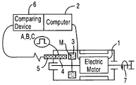
- FIGS. 1–2 are schematic diagrams of a rotating actuating system according to a first and a second embodiment of the present invention
- FIGS. 3 a and 3 b are schematic diagrams illustrating overhead and side views, respectively, of a translation actuating system according to another embodiment of the present invention.
- FIG. 4 is a longitudinal section view of an actuating system for a device that meters fuel in a heat engine
- FIG. 5 is a sectional view taken along line V—V of FIG. 4 .
- the invention relates to an actuating system comprising an electric motor 1 , for example, a stepper-type motor, which is controlled by a computer 2 configured to regulate a current supplied to the motor 1 as a function of a setpoint position of a member to be actuated.
- an electric motor 1 for example, a stepper-type motor
- a computer 2 configured to regulate a current supplied to the motor 1 as a function of a setpoint position of a member to be actuated.
- the member is actuated by a device which transmits the movement of the motor 1 to the member to be actuated.
- the actuation is obtained by controlling the motor 1 with a setpoint position of the member to be actuated, the setpoint position being selected, based on the type of the transmission device used, to move the member to a desired position.
- the actuating system actuates a device which meters an amount of fuel provided to a heat engine, such as, for example, an aeronautics turbine.
- a transmission device facilitates actuating a valve which supplies fuel to the heat engine, wherein the setpoint position is derived from an acceleration command provided by the pilot flying the plane having the heat engine.
- an encoder 3 having a main multipolar track M that is dependent on the movement of the motor 1 , is integrated into the actuating system and a sensor 4 , which can deliver two digital signals representative of the position of the encoder 3 , and hence, of the movements of the electric motor 1 .
- the encoder 3 is formed of a multipolar magnetic part on which a plurality of magnetized pairs of north and south poles are equally distributed with a constant angular width between neighboring poles to form the main track M.
- the encoder 3 is formed of an elastomeric part which is charged with magnetic particles, such as, for example, with ferrite, such as barium ferrite or strontium ferrite.
- the sensor 4 is fixed and includes at least two sensitive elements that are arranged to face the main track M with an air-gap AG defined between the sensitive elements and the main track M, to deliver two periodic electrical signals S 1 , S 2 in quadrature.
- the sensor 4 also includes means for digitizing the signals S 1 , S 2 , wherein two square digital position signals A, B are delivered in quadrature, wherein the signals are representative of the position of the encoder 3 .
- the sensitive elements are chosen from a group including Hall probes, magnetoresistors and giant magnetoresistors.
- this embodiment makes it possible to obtain position signals which do not depend on the amplitude of the read magnetic field; which are insensitive to the air-gap variations due to the movement of the encoder 3 ; and which are also insensitive to the decrease in the magnetic field due to the temperature.
- sensors 4 having two sensitive elements that deliver the signals S 1 and S 2 , are known.
- the sensor 4 includes means for interpolating the signals which make it possible to increase the resolution of the output digital signals A, B, so as to be able to use a smaller number of pairs of poles.
- the sensor 4 includes means for interpolating the signals which make it possible to increase the resolution of the output digital signals A, B, so as to be able to use a smaller number of pairs of poles.
- it is possible to use a high level of magnetic induction wherein it becomes possible to increase the robustness of the actuating system's operation with respect to the severe use conditions as well as the resolution of the position signals, and to do so without increasing the bulk of the encoder 3 .
- the actuating system further includes a device for processing the signals A, B, the device including counting means for determining, from an initial position, the actual position of the encoder 3 .
- the counting means includes a register within which the value of the position of the encoder 3 is increased or decreased by an incremental value corresponding to the number of fronts of signals A, B which are detected.
- the senor 4 and the processing device 5 may be integrated and provided on a silicon substrate or the like, for example, an AsGa substrate, to form an integrated circuit customized for a specific application, wherein the circuit is sometimes referred to as an ASIC to denote an integrated circuit that is designed in whole or in part as a function of requirements.
- a silicon substrate or the like for example, an AsGa substrate
- the circuit is sometimes referred to as an ASIC to denote an integrated circuit that is designed in whole or in part as a function of requirements.
- the initial position is fixed at zero when the actuating system is set in operation.
- the processing device 5 enables the relative position of the encoder 3 with respect to the initial position to be known. In other words, the distance separating the position of the encoder 3 from any initial position, which may vary with respect to a fixed reference point.
- the processing device 5 is designed to deliver the absolute position of the encoder 3 .
- Absolute position is understood to mean the distance separating the position of the encoder 3 at a given instant from a reference position of the encoder 3 with respect to a fixed reference position.
- the system includes means for determining a reference position, and the processing device 5 includes means which, upon detection of the reference position, assigns the reference position as the initial position.
- the means for determining the reference position is integrated in the encoder 3 .
- the encoder 3 also includes a singularity that is indexed to a reference position of the encoder 3 .
- the sensor also includes at least one sensitive element designed to detect the singularity of the encoder 3 .
- the encoder 3 may include the main multipolar track M or a top tour track T, the track M or T being provided with the singularity.
- At least one sensitive element is arranged to face the track M or T across the air-gap AG defined between the sensitive element and the track M or T to deliver a digital signal C having a pulse.
- the processing device 5 includes means which, upon detection of the pulse, assigns the reference position as an initial position.
- the magnetic singularity of the track M or T may be formed of two adjacent poles, the magnetic transition of which is different from the others.
- the means for determining the reference position are integrated in the transmission device.
- the transmission device may include a stop that is designed to interrupt the movement of the motor 1 in a reference position of the encoder 3
- the processing device 5 may include means which, upon interruption of the movement, assigns the reference position as the initial position.
- the encoder 3 may be formed of a metal or glass target on which the main track M and possibly the top track T have been engraved to form an optical motif that is analogous to the multipolar magnetic motif described above, the sensitive elements then being formed of optical detectors.
- the actuating system also includes a device 6 for comparing the actual position of the encoder 3 , that is to say the position determined by the processing device 5 , with the position of the encoder 3 that corresponds, in theory, to the applied setpoint.
- the comparison device 6 thus makes it possible to make the actuation safer by verifying, in real time, the correspondence between the movements of the electric motor 1 and the setpoint applied to the computer 2 .
- the comparison device 6 is integrated or provided within the computer 2 and includes a comparator for making a comparison between the position signal coming from the processing device 5 and the position signal derived from the setpoint.
- the integration being particularly simple and reliable on account of the digital nature of the two types of signal.
- the comparison device 6 includes alert means which, upon determination of a significant difference between the actual position and the theoretical position, is designed to emit a signal, for example, a light signal or audible signal, indicating an anomaly in the operation of the actuating system.
- alert means which, upon determination of a significant difference between the actual position and the theoretical position, is designed to emit a signal, for example, a light signal or audible signal, indicating an anomaly in the operation of the actuating system.
- the method of actuating the member using such an actuating system includes the following iterative steps of inputting a setpoint position of the member to the computer 2 ; determining the actual position of the encoder 3 ; comparing the actual position of the encoder 3 with the position of the encoder 3 that corresponds, in theory, to the applied setpoint; and, if the difference between the actual position and the theoretical position is greater than a predetermined threshold value, activating the alert means.
- the comparison device 6 includes, in addition to the alert means, an actuation feedback loop, which is controlled as a function of the determined difference between the actual position and the theoretical position.
- an actuation feedback loop which is controlled as a function of the determined difference between the actual position and the theoretical position.
- the processing device 5 may deliver signals which are representative of the speed of displacement of the encoder 3 , with the signals being used in the feedback loop.
- the method of actuating the member using such an actuating system includes the following iterative steps of inputting a setpoint position of the member to the computer 2 ; determining the actual position of the encoder 3 ; comparing the actual position of the encoder 3 with the position of the encoder 3 that corresponds, in theory, to the applied setpoint; and, if the difference between the actual position and the theoretical position is greater than a predetermined threshold value, controlling the feedback loop so as to apply to the computer 2 a position setpoint that is slaved to the difference.
- the methods may, where appropriate, include a step prior to the step of determining the initial position of the encoder 3 .
- the procedure may include a step of supplying the motor 1 with a current to position the encoder 3 in a reference position, the reference position being assigned in the processing device 5 as an initial position to subsequently determine the absolute position of the encoder 3 .
- the transmission device includes the rotor 7 of the electric motor 1 , wherein the encoder 3 is mounted on a part of the rotor that is opposite the member that is to be actuated.
- the transmission device includes a two-stage reducer 8 , the encoder 3 being mounted on the output rotor 9 of the reducer.
- the encoder 3 may also be mounted on the rotor 7 of the electric motor 1 or on the input rotor 10 of the reducer 8 .
- the encoder 3 and hence, the 30 multipolar tracks, are circular, the encoder being, for example, annular in shape and including a bore that allows it to be connected to the rotor 7 , 9 .
- the transmission device includes the rotor 7 , which is provided with a pinion 11 and a part 12 provided with a rack 13 , which are designed to transform the rotary movement of the rotor 7 into a linear movement of the part 12 , the encoder 3 being associated with the part.
- the part 12 may form part of the member that is to be actuated.
- the encoder 3 and hence, the multipolar tracks, are linear, the encoder being, for example, molded with the part 12 .
- the output rotor 9 includes a slot into which there is designed to be inserted the valve for supplying fuel to the metering device (not shown).
- the actuating system includes a casing 14 in which the motor 1 and the reducer 8 are housed to form a single assembly.
- the encoder 3 is fixed to an annular journal 15 of the gear wheel 16 which is associated with the output rotor 9 .
- This embodiment permits integration of an encoder 3 having a large diameter, which makes it possible to improve the precision with which the position of the encoder is measured without increasing the size of the actuating system or requiring additional mechanical parts.
- the sensor 4 is formed of a non-magnetic structural part in which the sensitive elements and the associated electronics are housed, the input/output connection of the sensor 4 , which is formed of a multiconductor cable 17 , projecting from the part to allow the connection of the sensor 4 to the computer 2 .
- the non-magnetic structural part includes a head 4 a on a side face of which there extends a body 4 b , the sensitive elements being disposed in the vicinity of the free side face 4 c of the body 4 b and the cable 17 extending from the side face of the head 4 a that is opposite the body 4 b .
- the part is designed so that the head 4 a has, on the body side, a free side surface 4 d.
- the sensor 4 is fixed in a housing 18 of the casing 19 of the reducer 8 , the housing being designed to receive the body 4 b by pressing the free side surface 4 d against the peripheral wall of the housing.
- the sensitive elements are precisely and reliably positioned to face the encoder 3 across an air-gap defined therebetween to be able to withstand severe use conditions.
- a wedge 20 may be placed between the peripheral wall of the housing and the free side surface 4 b to regulate the air-gap distance.
Landscapes
- Engineering & Computer Science (AREA)
- Human Computer Interaction (AREA)
- Manufacturing & Machinery (AREA)
- Physics & Mathematics (AREA)
- General Physics & Mathematics (AREA)
- Automation & Control Theory (AREA)
- Transmission And Conversion Of Sensor Element Output (AREA)
- Control Of Position Or Direction (AREA)
Applications Claiming Priority (2)
| Application Number | Priority Date | Filing Date | Title |
|---|---|---|---|
| FR0215280 | 2002-12-04 | ||
| FR0215280A FR2848358B1 (fr) | 2002-12-04 | 2002-12-04 | Systeme d'actionnement comprenant un capteur numerique de position |
Publications (2)
| Publication Number | Publication Date |
|---|---|
| US20040201356A1 US20040201356A1 (en) | 2004-10-14 |
| US7057364B2 true US7057364B2 (en) | 2006-06-06 |
Family
ID=32319973
Family Applications (1)
| Application Number | Title | Priority Date | Filing Date |
|---|---|---|---|
| US10/727,086 Expired - Fee Related US7057364B2 (en) | 2002-12-04 | 2003-12-04 | Actuation system comprising a digital position sensor |
Country Status (3)
| Country | Link |
|---|---|
| US (1) | US7057364B2 (fr) |
| EP (1) | EP1443373A3 (fr) |
| FR (1) | FR2848358B1 (fr) |
Cited By (2)
| Publication number | Priority date | Publication date | Assignee | Title |
|---|---|---|---|---|
| US20090060717A1 (en) * | 2007-06-27 | 2009-03-05 | Honeywell International, Inc. | Synchronous signal generator for trim balancing of jet engine |
| US20130131976A1 (en) * | 2011-11-17 | 2013-05-23 | Jonathan Hubbard | Position accuracy testing system |
Citations (3)
| Publication number | Priority date | Publication date | Assignee | Title |
|---|---|---|---|---|
| US4264850A (en) * | 1979-03-12 | 1981-04-28 | Dana Corporation | Position encoder interface for a servo control system |
| US4312033A (en) * | 1979-07-31 | 1982-01-19 | Sweeney James S | Digital motor control for positioning system |
| US5532583A (en) * | 1993-05-04 | 1996-07-02 | Storage Technology Corporation | System and method for calibrating a position sensing system |
Family Cites Families (8)
| Publication number | Priority date | Publication date | Assignee | Title |
|---|---|---|---|---|
| JPS5344777A (en) * | 1976-10-03 | 1978-04-21 | Ricoh Co Ltd | Closed loop servo-controlling system |
| US4129813A (en) * | 1977-07-26 | 1978-12-12 | The Singer Company | Method and apparatus for adaptive control of a stepper motor |
| JP2692274B2 (ja) * | 1989-06-22 | 1997-12-17 | 三菱電機株式会社 | 主軸位置・速度制御装置 |
| US5124625A (en) * | 1990-05-11 | 1992-06-23 | Matsushita Electric Industrial Co., Ltd. | Position control system |
| JPH0454885A (ja) * | 1990-06-19 | 1992-02-21 | Mitsubishi Electric Corp | サーボモータ用監視装置 |
| US5534692A (en) * | 1992-09-14 | 1996-07-09 | Sony Corporation | Method for detecting origin point of position sensor |
| JPH0697823A (ja) * | 1992-09-16 | 1994-04-08 | Okuma Mach Works Ltd | 位置制御装置 |
| FR2769088B1 (fr) * | 1997-09-26 | 1999-12-03 | Roulements Soc Nouvelle | Capteur digital de position relative |
-
2002
- 2002-12-04 FR FR0215280A patent/FR2848358B1/fr not_active Expired - Fee Related
-
2003
- 2003-11-24 EP EP03292908A patent/EP1443373A3/fr not_active Withdrawn
- 2003-12-04 US US10/727,086 patent/US7057364B2/en not_active Expired - Fee Related
Patent Citations (3)
| Publication number | Priority date | Publication date | Assignee | Title |
|---|---|---|---|---|
| US4264850A (en) * | 1979-03-12 | 1981-04-28 | Dana Corporation | Position encoder interface for a servo control system |
| US4312033A (en) * | 1979-07-31 | 1982-01-19 | Sweeney James S | Digital motor control for positioning system |
| US5532583A (en) * | 1993-05-04 | 1996-07-02 | Storage Technology Corporation | System and method for calibrating a position sensing system |
Cited By (4)
| Publication number | Priority date | Publication date | Assignee | Title |
|---|---|---|---|---|
| US20090060717A1 (en) * | 2007-06-27 | 2009-03-05 | Honeywell International, Inc. | Synchronous signal generator for trim balancing of jet engine |
| US20130131976A1 (en) * | 2011-11-17 | 2013-05-23 | Jonathan Hubbard | Position accuracy testing system |
| US9163948B2 (en) * | 2011-11-17 | 2015-10-20 | Speedgauge, Inc. | Position accuracy testing system |
| US9897451B2 (en) | 2011-11-17 | 2018-02-20 | Speedgauge, Inc. | Position accuracy testing system |
Also Published As
| Publication number | Publication date |
|---|---|
| FR2848358A1 (fr) | 2004-06-11 |
| EP1443373A3 (fr) | 2004-10-13 |
| EP1443373A2 (fr) | 2004-08-04 |
| US20040201356A1 (en) | 2004-10-14 |
| FR2848358B1 (fr) | 2005-03-18 |
Similar Documents
| Publication | Publication Date | Title |
|---|---|---|
| US6479987B1 (en) | Angle encoder with four hall sensors and method for angle determination of output signals of the four hall sensors | |
| US8461827B2 (en) | Roller bearing arrangement with a sensor unit | |
| US5880586A (en) | Apparatus for determining rotational position of a rotatable element without contacting it | |
| US10175066B2 (en) | Sensor system for detecting absolute rotational angle of a shaft | |
| CN110220538B (zh) | 多匝转动编码器 | |
| CN101660892B (zh) | 用于测量旋转的可移动部件的轴向移动的系统和方法 | |
| CN103256911B (zh) | 检测在车辆中的旋转构件处的旋转角度的传感器组件 | |
| US11984837B2 (en) | Method for determining an angular position of a rotating component, in particular of an electric motor for a clutch actuation system of a vehicle | |
| US6496784B1 (en) | Method for compensating the offset of angle sensors | |
| US12098967B2 (en) | Torque and angle sensing device | |
| JP7191567B2 (ja) | 組み立て品 | |
| US12111220B2 (en) | Sensor assembly for sensing a steering torque and an absolute angular position, and sensor device having said sensor assembly | |
| GB2197483A (en) | Determining rotational speed using magnetic sensors | |
| KR20160146758A (ko) | 전동기 회전자의 위치 인식 방법, 전동기 회전자의 위치 결정을 위한 타깃, 및 전동기 | |
| CN111433568A (zh) | 用于确定围绕至少一个旋转轴线旋转的旋转元件的至少一个旋转特性的传感器系统 | |
| EP4075100B1 (fr) | Capteur de proximité pour détecter la position et la vitesse d'un arbre rotatif | |
| CN114270132A (zh) | 用于捕获可旋转轴的扭矩和角度位置的传感器组件 | |
| US7057364B2 (en) | Actuation system comprising a digital position sensor | |
| US6265866B1 (en) | Measuring device for determining the position of a control element with temperature related measurement errors correction | |
| US20060113989A1 (en) | Redundant pedal position sensor | |
| JP2005531736A (ja) | ショックアブソーバ並びにショックアブソーバ運動を検出する装置 | |
| KR102216270B1 (ko) | 항공기용 전기식 구동장치의 아날로그 홀 센서 방식을 이용한 절대위치각 측정장치 | |
| US7764035B2 (en) | Electric actuator for aircraft flight control | |
| CN111902703A (zh) | 测量活动体相对于固定体的位置的方法 | |
| Kapser et al. | GMR sensors in automotive applications |
Legal Events
| Date | Code | Title | Description |
|---|---|---|---|
| AS | Assignment |
Owner name: BDSA, FRANCE Free format text: ASSIGNMENT OF ASSIGNORS INTEREST;ASSIGNORS:BALLAS, GERARD;NICOT, CHRISTOPHE;REEL/FRAME:015450/0530;SIGNING DATES FROM 20040507 TO 20040510 |
|
| AS | Assignment |
Owner name: S.N.R. ROULEMENTS, FRANCE Free format text: CORRECTIVE ASSIGNMENT TO CORRECT THE ASSIGNEE'S INFORMATION PREVIOUSLY RECORDED ON REEL 015450 FRAME 0530;ASSIGNORS:BALLAS, GERARD;NICOT, CHRISTOPHE;REEL/FRAME:017979/0631;SIGNING DATES FROM 20040507 TO 20040510 |
|
| FEPP | Fee payment procedure |
Free format text: PAYOR NUMBER ASSIGNED (ORIGINAL EVENT CODE: ASPN); ENTITY STATUS OF PATENT OWNER: LARGE ENTITY |
|
| REMI | Maintenance fee reminder mailed | ||
| LAPS | Lapse for failure to pay maintenance fees | ||
| STCH | Information on status: patent discontinuation |
Free format text: PATENT EXPIRED DUE TO NONPAYMENT OF MAINTENANCE FEES UNDER 37 CFR 1.362 |
|
| FP | Lapsed due to failure to pay maintenance fee |
Effective date: 20100606 |