US7073609B2 - Apparatus and methods for imaging wells drilled with oil-based muds - Google Patents
Apparatus and methods for imaging wells drilled with oil-based muds Download PDFInfo
- Publication number
- US7073609B2 US7073609B2 US10/674,179 US67417903A US7073609B2 US 7073609 B2 US7073609 B2 US 7073609B2 US 67417903 A US67417903 A US 67417903A US 7073609 B2 US7073609 B2 US 7073609B2
- Authority
- US
- United States
- Prior art keywords
- current
- property
- sensor
- electrode
- formation
- Prior art date
- Legal status (The legal status is an assumption and is not a legal conclusion. Google has not performed a legal analysis and makes no representation as to the accuracy of the status listed.)
- Expired - Lifetime, expires
Links
Images


Classifications
-
- G—PHYSICS
- G01—MEASURING; TESTING
- G01V—GEOPHYSICS; GRAVITATIONAL MEASUREMENTS; DETECTING MASSES OR OBJECTS; TAGS
- G01V3/00—Electric or magnetic prospecting or detecting; Measuring magnetic field characteristics of the earth, e.g. declination, deviation
- G01V3/18—Electric or magnetic prospecting or detecting; Measuring magnetic field characteristics of the earth, e.g. declination, deviation specially adapted for well-logging
- G01V3/20—Electric or magnetic prospecting or detecting; Measuring magnetic field characteristics of the earth, e.g. declination, deviation specially adapted for well-logging operating with propagation of electric current
- G01V3/24—Electric or magnetic prospecting or detecting; Measuring magnetic field characteristics of the earth, e.g. declination, deviation specially adapted for well-logging operating with propagation of electric current using AC
Definitions
- the invention relates generally to resistivity logging tools. More particularly, the invention relates to tools and methods of resistivity measurements in wells drilled with oil-based muds.
- the GSTTM tool provides azimuthal resistivity measurements close to the drilling bit. The azimuthal resistivity measurements can be used to steer the drill bit to follow a path to the hydrocarbon zones and stay away from water zones. The GSTTM tool can also determine whether the well path is getting out of the pay zone.
- U.S. Pat. No. 5,235,285 issued to Clark et al. and assigned to the assignee of the present invention discloses a tool that measures the resistivity at the bit.
- tools based on this and related principles include one sold under the trade name of RABTM (resistivity at the bit) and another sold under the trade name of GVRTM (geovision resistivity) by Schlumberger Technology Corporation (Houston, Tex.).
- RABTM resistivity at the bit
- GVRTM division resistivity
- Schlumberger Technology Corporation Houston, Tex.
- These tools are capable of delivering full borehole resistivity images of the reservoir rock being drilled. This capability makes it possible to detect small geological structures or thin formation layers while drilling and allows one to image reservoir structural and stratigraphic dips. Being able to detect and visualize the well path while drilling is crucial in placing the well in the proper location—to stay within the pay zone and to avoid crossing the boundary.
- the first device developed specifically for the measurements of formation dips in wells drilled with OBM was an OBM dipmeter based on capacitive coupling.
- OBM dipmeter based on capacitive coupling.
- One example of such an OBM dipmeter is disclosed in U.S. Pat. No. 3,973,181 issued to Calvert and assigned to the assignee of the present invention.
- This device operates at high frequency (10 MHz) to minimize the effect of standoffs.
- a single guarded (insulated) button was mounted on each of the four pads of a standard dipmeter.
- this tool can image four sectors of the borehole; however, it does not have enough coverage of the borehole to provide full borehole images.
- LWD logging-while-drilling
- MWD measurement-while-drilling
- ADNTM azimuthal density neutron tool sold under the trade name of ADNTM by Schlumberger Technology Corporation (Houston, Tex.).
- ADNTM can only provide a 16-sector density image.
- the densities of typical rock formations have a more limited range, typically 2 to 3 g/cc, as compared to the range of resistivities, typically 0.2 to 2000 ohm-meter. Therefore, an imaging tool based on resistivity is more desirable.
- a logging sensor used on an LWD tool may not be able to maintain contact with the borehole wall at all times.
- Tool standoffs may reduce the accuracy of the measurements. Therefore, it is desirable that a sensor to be used on an LWD tool have the ability to minimize or eliminate the standoffs.
- a resistivity logging sensor in accordance with one embodiment of the invention includes a sensor body; a first current injector electrode disposed on the sensor body, wherein the first current injector electrode is electrically insulated from the sensor body; at least two current return electrodes disposed on the sensor body at a selected distance from the first current injector electrode, wherein the at least two current return electrodes are disposed proximate to each other and are electrically insulated from the sensor body; and an electrical source configured to energize the first current injector electrode with a current having a voltage of no less than 50 mvolts and a frequency of no less than 1 KHz.
- a method in accordance with one embodiment of the invention includes injecting a current into a formation by energizing a current injector electrode; measuring a property of a first current returning to a first current return electrode disposed at a distance from the current injector electrode; measuring a property of a second current returning to a second current return electrode disposed proximate the first current return electrode; and determining the formation property from a difference measurement derived from the property of the first current and the property of the second current.
- a method in accordance with one embodiment of the invention includes injecting a first current into a formation by energizing a first current injector electrode; measuring a property of a first current returning to a first current return electrode disposed at a distance from the first current injector electrode; measuring a property of a second current returning to a second current return electrode disposed proximate the first current return electrode; injecting a second current into the formation by energizing a second current injector electrode; measuring a property of a third current returning to the first current return electrode; measuring a property of a fourth current returning to the second current return electrode; and determining the formation property from a difference measurement derived from the property of the first current, the property of the second current, the property of the third current, and the property of the fourth current.
- FIG. 1A shows a resistivity logging sensor in accordance with one embodiment of the invention.
- FIG. 1B shows an electrode array for a resistivity logging sensor in accordance with one embodiment of the invention.
- FIG. 2 shows a resistivity logging sensor in accordance with one embodiment of the invention in the process of logging a formation.
- FIG. 3 shows a schematic of various impedance encountered by a current injected into a formation and returning to an electrode.
- FIG. 4 shows a chart illustrating magnitudes of currents returning to the tool as a function of formation resistivity and tool standoffs.
- FIG. 5 shows a chart illustrating formation impedances computed from difference measurements as a function of formation resistivity and tool standoffs.
- FIG. 6 shows a resistivity logging sensor in accordance with another embodiment of the invention.
- FIG. 7 shows a schematic of various impedance encountered by currents injected into a formation and returning to electrodes according to a sensor of FIG. 6 .
- FIG. 8 shows a resistivity logging sensor in accordance with another embodiment of the invention.
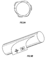
- FIG. 9A shows a cross section view of a PowerDrive and three deployable pads in a wellbore.
- FIG. 9B shows a downhole tool having a resistivity logging sensor disposed on a deployable pad on the downhole tool in accordance with one embodiment of the invention.
- FIG. 10 shows a downhole tool having extendable pistons for including a resistivity logging sensor in accordance with one embodiment of the invention.
- FIG. 11 illustrates a method of resistivity logging and geosteering in accordance with one embodiment of the invention.
- Embodiments of the invention relate to apparatus and methods for resistivity measurements and formation imaging.
- a tool in accordance with embodiments of the invention is capable of operating in oil-based muds (OBM) and may be used while drilling.
- OBM oil-based muds
- embodiments of the invention can monitor and/or minimize the tool standoff effects.
- a resistivity logging tool can be based on one of the two sensor mechanisms: electrical dipoles (using generally metallic electrodes) and magnetic dipoles (using generally induction coils or resonant cavities at VHF).
- electrical dipoles using generally metallic electrodes
- magnetic dipoles using generally induction coils or resonant cavities at VHF.
- Embodiments of the invention relate to tools using metallic electrode sensors.
- new LWD or MWD sensors are deigned to be able to operate in OBM. These new sensors are capable of providing formation images for geosteering as well as other geological applications.
- the LWD sensors of the invention are based on a configuration similar to the original RAB configuration, which was designed to operate in water-based muds (WBM).
- WBM water-based muds
- HFRAB high frequency RAB
- FIG. 1A shows an HFRAB 100 in accordance with embodiments of the invention.
- This HFRAB is a modification of a prior art RAB sensor.
- a ring electrode 11 is disposed on the drill collar 19 , but insulated from the drill collar 19 using a suitable insulating material 18 .
- the ring electrode 11 acts as a current source (current injector) in a manner similar to a toroidal transmitter of the RABTM disclosed in U.S. Pat. No. 5,235,285.
- a ring electrode is expected to be more efficient at high frequencies, embodiments of the invention may also use a troroidal transformer, like the RABTM.
- a selected voltage difference (e.g., 100V) is applied between the current injector electrode 11 and the surrounding drill collar 19 .
- the applied voltage is between 50 mV and 1000 volts, more preferably about 100 volts.
- the voltage difference forces a current to flow from the current injector electrode 11 through the borehole into the formation and finally returns to the button electrodes 12 and 13 .
- the current return electrodes are shown as button electrodes in FIGS. 1A , one of ordinary skill in the art would appreciate that these electrodes may have other configurations, such as ring electrodes or toroidal transformers. Accordingly, these electrodes will be generally referred to as “current return electrodes.”
- the current return electrodes are button electrodes because they can provide good vertical resolution and azimuthal sensitivity.
- the currents for current injector electrode 11 are applied at relatively high frequencies (e.g., about 1 KHz–about 1.5 GHz, preferably between 1 MHz and 500 MHz, and more preferably about 50 MHz). Capacitive coupling is more efficient at higher frequencies. As a result, the contribution of mud impedance is smaller relative to the impedance constituted by the rock formation at higher frequencies.
- two or more current return electrodes are provided on each tool.
- two current return electrodes 12 and 13 are included in the HFRAB 100 shown in FIG. 1A .
- the two or more current return electrodes preferably are arranged in proximity such that their borehole effects are similar. In addition, close proximity of these electrodes provides better resolution. If more than two electrodes are included, they may be organized in an array as shown in FIG. 1B .
- FIG. 2 shows a sectional view of an exemplary tool configuration in accordance with one embodiment of the invention.
- the current injector electrode 11 comprises a ring of about 1 to 5 inches wide embedded in an insulating material 18 disposed around the periphery (in a recess about 3 to 15 inches wide) of tool collar 19 .
- the current return electrodes 12 and 13 each comprising a button having a 1 ⁇ 2-inch diameter, are preferably embedded in insulating materials with a separation of about 1.00 inches between the centers of the two electrodes.
- conductive paths 21 and 22 are also shown.
- the conductive path 21 leads from the current injector electrode 11 into formation 101 and returns to the current return electrode 12
- the conductive path 22 leads from the current injector electrode 11 into the formation 101 and returns to the current return electrode 13 .
- FIG. 3 shows a schematic of impedances encountered by the currents flowing along a conductive path.
- an electrical source 31 is applied to the current injector electrode 11 , which then emits a current 30 .
- the emitted current 30 first encounters the impedance of the mud (Z c ) in front of the current injector electrode 11 .
- the current 30 then enters the formation 101 and encounters the impedance of the formation (Z f ).
- the current 30 finally exits the formation 101 and encounters the mud impedance (Z b1 ) in front of the current return electrode 12 before returning to the current return electrode 12 , which is referred to as the first button electrode (b 1 ) in the schematic of FIG. 3 .
- the total impedance along the conductive path 21 may be derived from a ratio of the voltage (V) of the current injected into the formation 101 by the current injector electrode 11 and the measured current magnitude (I b1 ) at the current return electrode 12 .
- V I b ⁇ ⁇ 1 is a summation of the three impedances, Z c , Z f , and Z b1 along the conductive path 21 , i.e.,
- V I b ⁇ ⁇ 1 Z C + Z f + Z b ⁇ ⁇ 1 . ( 1 ) Note that if the tool is operated with a relatively high frequency current, then the mud impedances become negligible relative to the formation impedance, i.e., Z f >>Z c and Z b1 . As a result,
- the formation impedance Z f is a function of both rock formation resistivity and dielectric constant.
- V I b ⁇ ⁇ 2 Z C + Z f + ⁇ ⁇ ⁇ Z f ⁇ ⁇ 12 + Z b ⁇ ⁇ 2 ( 2 )
- V is the voltage of the current emitted from the current injector electrode 11
- I b2 is the current measured at current return electrode 13
- Z c is the impedance of the mud in front of the current injector electrode 11
- Z f is the impedance of the formation corresponding to the section traversed by the conductive path 21
- ⁇ Z f12 is the impedance of the additional section of the formation that the conductive path 22 needs to traverse
- Z b2 is the impedance of mud in front of the current return electrode 13 .
- This provides a convenient means to measure formation impedance that is independent of tool standoffs as long as the mud impedance in from of the two current return electrodes are similar (Z b2 ⁇ Z b1 ) or their difference is insignificant relative to the formation impedance (
- the section of the formation that contributes to ⁇ Z f12 is a function of the separation between the two measuring electrodes. Therefore, the vertical resolution of such difference measurements depends on the physical separation between the measuring electrodes.
- the measurement electrodes are disposed in proximity to each other to enable high-resolution imaging of the formation. For example, in the embodiment shown in FIG. 2 , the two measurement electrodes are arranged 1.00 inches apart. This sensor should be able to provide borehole images with a resolution on the order of 1 or 2 inches.
- the difference measurement described above may be a phase-shift difference, an amplitude difference (attenuation), or an amplitude ratio (measured in dB).
- the amplitude ratio is also a difference measurement, but it is equivalent to a difference between the logarithm of the amplitudes.
- the responses of a tool in accordance with embodiments of the invention may be simulated using a suitable program, such as the finite element simulation program sold under the trade name of FEMLAB® by COMSOL, Inc. (Burlington, Mass.).
- a suitable program such as the finite element simulation program sold under the trade name of FEMLAB® by COMSOL, Inc. (Burlington, Mass.).
- Results from a simulation of the basic responses of a simple HFRAB sensor (as shown in FIG. 2 ) mounted on a drill collar is shown in FIG. 4 .
- the simulation is performed with a tool having the dimensions shown in FIG. 2 and operated with a current having a frequency of 50 MHz.
- the total currents collected by these current return electrodes are normalized according to the effective electrode surface.
- FIG. 4 shows the results of such a simulation, in which the amplitudes of the currents measured by the button electrodes are presented as a function of total formation resistivity (R t ) and for different values of standoffs.
- Curve pairs a, b, c, and d represent 0, 0.5, 1.0 and 1.5 inch standoffs, respectively.
- the higher magnitude curve is that of the first button electrode (I b1 , shown as electrode 12 in FIG. 2 ) and the lower magnitude curve is that of the second electrode (I b2 , shown as electrode 13 in FIG. 2 ).
- the current amplitudes in general decrease as R t increases. This is expected because higher formation resistivity contributes to higher formation impedance, which in turn contributes to a higher total impedance experienced by the currents returning to the electrodes.
- the formation impedance Z f is substantially greater than the impedances of mud (Z c , Z b1 or Z b2 ). Therefore, the measured currents are dominated by the formation impedance (Z f ), hence the relationship between the measured currents (I b1 and I b2 ) and the formation resistivity (R t ) is mostly linear. Note that formation impedance is actually a function of both the capacitance and the resistivity of the formation. However, the capacitance of the formation is not changed in this simulation. Note also that at extremely high R t , formation dielectric effects become non-negligible and the rate of decreases of the measured currents (I b1 and I b2 ) becomes slower.
- the measured current magnitudes (I b1 and I b2 ) do not change as fast as they do at higher resistivities. This is because the mud impedances become substantial relative to the formation impedance, which is lower due to lower formation resistivities.
- the deviation from the linear relationship starts at higher R t (about 2 ohm-meter) than that (about 0.5 ohm-meter) at smaller standoffs (e.g., curves a).
- FIG. 4 also shows that the standoff effects are substantially identical on the currents measured by the two button electrodes. This is apparent from the fact that each pair of the curves within the same standoff have substantially identical shapes, e.g., the curves “flatten out” at the same formation resistivity. Therefore, a difference measurement between the two buttons should cancel the standoff effects. Accordingly, the formation impedance may be derived from the differential impedance measurements from the two electrodes, regardless of the tool standoffs, as shown in equation (4).
- FIG. 5 shows a plot of the apparent impedance of the formation ( ⁇ Z f12 ) in front of the two current return electrodes, which is derived from the difference measurements shown in FIG. 4 , as a function of the formation resistivity (R t ).
- the formation impedance ( ⁇ Z f12 ) is calculated according to equation (4) using results shown in FIG. 4 . It is apparent from FIG. 5 that the formation impedances ( ⁇ Z f12 ) in front of the two current return electrodes are independent of tool standoffs, but are dependent on the formation resistivities with a substantially linear relationship.
- the slope of the linear segment in the high resistivity region (e.g., R t >20 ohm-meter) is different from that in the low resistivity region (e.g., R t ⁇ 10 ohm-meter). This change in the slopes most likely arises from the fact that dielectric effects become non-negligible in high resistivity formations.
- the formation impedance ( ⁇ Z f12 ) can be derived from difference measurements using two electrodes. This approach is valid only if the mud impedances in front of the two electrodes are substantially the same or if the differences are negligible when compared to the formation impedance, i.e., Z b1 ⁇ Z b2 or
- an HFRAB tool is equipped with three or more current return electrodes 12 , 13 , and 14 (shown in FIG. 6 ) for providing a compensated difference measurement and for monitoring the standoff effects.
- This tool is similar to that shown in FIG. 1 ; however, it includes an additional current return electrode 14 .
- the currents measured by the three current return electrodes 12 , 13 , 14 can be used to monitor whether the mud impedances in front of these current return electrodes 12 , 13 , 14 are substantially identical.
- FIG. 7 shows a schematic illustrating three conductive paths leading to each of the three current return electrodes 12 , 13 , 14 shown in FIG. 6 .
- the currents that return to electrodes 12 and 13 will experience impedances as shown in equations (1) and (2), respectively. Equations (1) and (2) are reproduced below for easy comparison.
- the current returning to electrode 14 will experience a total impedance as shown in equation (5):
- V I b ⁇ ⁇ 1 Z C + Z f + Z b ⁇ ⁇ 1 ( 1 )
- V I b ⁇ ⁇ 2 Z C + Z f + ⁇ ⁇ ⁇ Z f ⁇ ⁇ 12 + Z b ⁇ ⁇ 2 ( 2 )
- V I b ⁇ ⁇ 3 Z C + Z f + ⁇ ⁇ ⁇ Z f ⁇ ⁇ 12 + ⁇ ⁇ ⁇ Z f ⁇ ⁇ 23 + Z b ⁇ ⁇ 3 ( 5 )
- ⁇ Z f23 represents the formation impedance in front of button electrodes 13 and 14
- Z b3 is the impedance in front of electrode 14
- other terms have the same meanings as previously defined in reference to equation (2).
- FIG. 8 shows a resistivity tool in accordance with one embodiment of the invention.
- the tool 800 includes two current injector electrodes 81 , 82 that are equally spaced from the two current return electrodes 83 and 84 . These electrodes are similar to those shown in FIG. 1 and are similarly arranged.
- the main difference between the tool 100 shown in FIG. 1A (or FIG. 2 ) and the tool 800 shown in FIG. 8 lies in the inclusion of an additional current injector electrode 82 in tool 800 .
- the equations described with reference to tool 100 in FIG. 1 (or FIG. 2 ) are generally applicable to the tool 800 in FIG. 8 .
- the current injector electrodes 81 and 82 are energized at different times (i.e., by time multiplexing), then two sets of measurements may be acquired with the current return electrodes 83 , 84 .
- the impedance obtained from the difference measurements between the two button electrodes 83 and 84 is as follows:
- V I b ⁇ ⁇ 2 UP - V I b ⁇ ⁇ 1 UP ⁇ ⁇ ⁇ Z f ⁇ ⁇ 12 UP + Z b ⁇ ⁇ 2 UP - Z b ⁇ ⁇ 1 UP ( 8 )
- UP indicates that the upper current injector electrode 81 is energized.
- the impedance of the formation can be obtained from the difference measurements between the two button electrodes 83 and 84 as follows:
- V I b1 DN - V I b2 DN ⁇ ⁇ ⁇ Z f21 DN + Z b1 DN - Z b2 DN ( 9 ) where DN indicates that the lower (down) current injector electrode 82 is energized.
- Z b1 UP Z b1 DN
- Z b2 UP Z b2 DN
- Equation (10) shows that the average of the UP and DOWN differential impedance measurements between the two current return electrodes 83 , 84 depends only on the formation properties in the region adjacent to the two current return electrodes 83 , 84 . Therefore, the formation impedance obtained using equation (10) is immune to tool standoff effects. That is, the tool 800 shown in FIG. 8 is standoff-compensated.
- a resistivity measurement sensor (such as those shown in FIGS. 1 , 6 , 8 , or a variant thereof) may be included on a pad of a drilling/logging tool.
- Deployable pads have been extensively used in wireline tools to minimize logging tool standoffs and to maximize and maintain sensor contacts with the borehole wall.
- the use of deployable pads in LWD or MWD tools is rare due to the harsh conditions encountered during drilling.
- a PowerDriveTM tool is introduced by Schlumberger Technology Corporation (Houston, Tex.).
- the PowerDriveTM tools include hydraulically controlled pads that may be used to steer the drill bit by a push-the-bit mechanism.
- the three pads of a PowerDriveTM tool can deployed to produce boreholes with much less rugosity and dogleg severity.
- FIG. 9A shows a cross sectional view of a collar equipped with three PowerDriveTM pads 91 disposed on a PowerDriveTM tool 90 that is in the process of drilling a borehole 95 .
- the deployable pads on a PowerDriveTM tool may also be used to include sensors for formation property measurements.
- Some embodiments of the present invention include HFRAB sensors on at least one pad of a PowerDriveTM directional drilling tool.
- the sensor of the invention may maintain its contact with the borehole wall to eliminate or minimize standoff effects.
- FIG. 9B shows a HFRAB in accordance with one embodiment of the invention disposed on one of the Power Drive pads.
- the HFRAB includes a current injector electrode 92 and five button electrodes 93 arranged in an array.
- the HFRAB tool shown is for illustration, and other variations (e.g., with different number of current return electrodes) may also be used without departing from the scope of the invention.
- FIG. 9B shows that the current injector electrode and the current return electrodes are all included on the deployable pads, other configurations are possible and are expressly within the scope of the invention.
- the current injector electrode may be included on the collar and the current return electrodes included on the deployable pads.
- FIG. 10 shows a tool 100 a having four pressure-compensated pistons 18 a in accordance with this co-pending application.
- the pistons 18 a have fluid-filled reservoirs 13 a that are kept at a pressure substantially identical to the pressure outside the tool (e.g., the pressure in a borehole 101 a ).
- the pistons 18 a may be deployed, for example, by a bias force from the springs 23 a behind the pistons.
- Each piston 18 a includes a pad 19 a , which may be used to include desired sensors, such as the HFRAB sensors of the present invention.
- FIG. 11 shows a method for measuring a formation property in accordance with one embodiment of the invention.
- a resistivity sensor such as that shown in FIG. 1A or FIG. 8 , is disposed in a borehole drilled with OBM.
- a current from a current injector electrode is injected through the OBM in the borehole and into the formation (step 112 ).
- two current injectors are provided (see FIG. 8 ). The two current injectors may be energized at different times or at different frequencies to provide two sets of measurements for canceling the standoff effects. Currents that travel in the formation and return to the measurement electrodes are measured.
- At least two electrodes disposed at a distance from the current injector electrode are used to measure the return currents (step 114 ).
- the measurements may be performed with the sensor pressed against borehole wall, if the sensor is disposed on a disployable pads as in a PowerDriveTM tool or on a piston as shown in FIG. 10 .
- the measured current magnitudes from the at least two measurement electrodes are analyzed to provide the formation impedance (step 116 ).
- the magnitudes of the measured currents are subtracted to give a difference measurement that provides an indication of the formation impedance regardless of the tool standoff.
- at least three measurement electrodes are used to measure the return currents. Then, a comparison between the magnitudes of the currents detected by the electrodes are used to monitor the tool standoff effects and to derive formation impedances. If the measurements were made with two current injectors (see FIG. 8 ), then the two sets of measurements may be used to cancel the effects of tool standoffs. That is the two sets of measurements may be used to derived “standoff-compensated” measurements of formation impedance.
- the derived formation impedance, the measured return currents, voltages, of the difference measurements between two or more electrodes may be used to monitor the environment of the LWD tool. Accordingly, these parameters may be used to control the drilling directions as in geosteering (step 118 ).
- a sensor capable of measuring the resistivity of a formation drilled with OBM capable of measuring the resistivity of a formation drilled with OBM.
- the sensor can provide high resolution images of the borehole.
- the resistivity sensors in accordance with the invention may used with an LWD or MWD tool.
- the resistivity sensor may be disposed on deployable pads or extendable buttons on the LWD or MWD tools so that the sensor can contact the borehole wall to minimize the resistivity barrier of the OBM.
- Methods of the invention can provide indications of tool standoffs and/or compensate for tool standoffs.
- the resistivity measurements obtained using a sensor of the invention are not sensitive to tool standoffs. These measurements may be used to control the drilling directions.
Landscapes
- Life Sciences & Earth Sciences (AREA)
- Engineering & Computer Science (AREA)
- Environmental & Geological Engineering (AREA)
- Geology (AREA)
- Remote Sensing (AREA)
- Physics & Mathematics (AREA)
- General Life Sciences & Earth Sciences (AREA)
- General Physics & Mathematics (AREA)
- Geophysics (AREA)
- Geophysics And Detection Of Objects (AREA)
- Investigating Or Analyzing Materials By The Use Of Electric Means (AREA)
Priority Applications (4)
| Application Number | Priority Date | Filing Date | Title |
|---|---|---|---|
| US10/674,179 US7073609B2 (en) | 2003-09-29 | 2003-09-29 | Apparatus and methods for imaging wells drilled with oil-based muds |
| CA002476976A CA2476976C (fr) | 2003-09-29 | 2004-08-09 | Appareil et methodes d'imagerie de puits perfores au moyen de boues a base d'huile |
| GB0419044A GB2406384B (en) | 2003-09-29 | 2004-08-26 | Apparatus and methods for imaging wells drilled with oil-based drilling muds |
| GB0611691A GB2424489B (en) | 2003-09-29 | 2004-08-26 | Imaging wells drilled with oil-based muds |
Applications Claiming Priority (1)
| Application Number | Priority Date | Filing Date | Title |
|---|---|---|---|
| US10/674,179 US7073609B2 (en) | 2003-09-29 | 2003-09-29 | Apparatus and methods for imaging wells drilled with oil-based muds |
Publications (2)
| Publication Number | Publication Date |
|---|---|
| US20050067190A1 US20050067190A1 (en) | 2005-03-31 |
| US7073609B2 true US7073609B2 (en) | 2006-07-11 |
Family
ID=33132092
Family Applications (1)
| Application Number | Title | Priority Date | Filing Date |
|---|---|---|---|
| US10/674,179 Expired - Lifetime US7073609B2 (en) | 2003-09-29 | 2003-09-29 | Apparatus and methods for imaging wells drilled with oil-based muds |
Country Status (3)
| Country | Link |
|---|---|
| US (1) | US7073609B2 (fr) |
| CA (1) | CA2476976C (fr) |
| GB (2) | GB2406384B (fr) |
Cited By (11)
| Publication number | Priority date | Publication date | Assignee | Title |
|---|---|---|---|---|
| US20070007967A1 (en) * | 2005-07-08 | 2007-01-11 | Baker Hughes Incorporated | High resolution resistivity earth imager |
| US20080288171A1 (en) * | 2007-05-15 | 2008-11-20 | Baker Hughes Incorporated | Dual standoff resistivity imaging instrument, methods and computer program products |
| US20090295392A1 (en) * | 2008-05-29 | 2009-12-03 | Baker Hughes Incorporated | Resistivity Imager in Non-Conductive Mud for LWD and Wireline Applications |
| EP2182391A1 (fr) * | 2008-10-31 | 2010-05-05 | Services Pétroliers Schlumberger | Outil pour l'imagerie d'un environnement d'extraction |
| EP2182392A1 (fr) * | 2008-10-31 | 2010-05-05 | Services Pétroliers Schlumberger | Outil pour l'imagerie d'un environnement d'extraction |
| US20110089951A1 (en) * | 2009-10-19 | 2011-04-21 | Smith International, Inc. | Microresistivity Imaging in Conductive and Nonconductive Drilling Fluid |
| US20110114309A1 (en) * | 2008-10-31 | 2011-05-19 | Richard Bloemenkamp | Sensor for determining downhole parameters and methods for using same |
| EP2565374A1 (fr) | 2011-08-29 | 2013-03-06 | Services Pétroliers Schlumberger | Compensateur de pression de trou de forage et son procédé |
| US20150177407A1 (en) * | 2008-10-31 | 2015-06-25 | Schlumberger Technology Corporation | Tool for Imaging A Downhole Environment |
| US9068436B2 (en) | 2011-07-30 | 2015-06-30 | Onesubsea, Llc | Method and system for sampling multi-phase fluid at a production wellsite |
| WO2016195715A1 (fr) * | 2015-06-05 | 2016-12-08 | Halliburton Energy Services, Inc. | Système de capteur pour mesures galvaniques en puits |
Families Citing this family (35)
| Publication number | Priority date | Publication date | Assignee | Title |
|---|---|---|---|---|
| FR2864439B1 (fr) * | 2003-12-30 | 2010-12-03 | Image Guided Therapy | Dispositif de traitement d'un volume de tissu biologique par hyperthermie localisee |
| US8022983B2 (en) * | 2005-04-29 | 2011-09-20 | Schlumberger Technology Corporation | Borehole imaging system for conductive and resistive drilling fluids |
| BRPI0613349A2 (pt) * | 2005-06-20 | 2011-01-04 | Halliburton Energy Serv Inc | método de diagrafia de resistividade e aparelho de diagrafia de resistividade |
| US7490428B2 (en) * | 2005-10-19 | 2009-02-17 | Halliburton Energy Services, Inc. | High performance communication system |
| WO2007055784A2 (fr) * | 2005-11-04 | 2007-05-18 | Halliburton Energy Services, Inc. | Outil de mise en image de boue a base d'huiles qui mesure la phase et l'amplitude de tension |
| US7696756B2 (en) * | 2005-11-04 | 2010-04-13 | Halliburton Energy Services, Inc. | Oil based mud imaging tool with common mode voltage compensation |
| US7579841B2 (en) * | 2005-11-04 | 2009-08-25 | Halliburton Energy Services, Inc. | Standoff compensation for imaging in oil-based muds |
| CA2611753C (fr) * | 2005-11-10 | 2013-06-25 | Halliburton Energy Services, Inc. | Amplificateur d'electrode deplacee |
| WO2007070777A2 (fr) * | 2005-12-13 | 2007-06-21 | Halliburton Energy Services, Inc. | Correction du courant de fuite multifrequence pour l'imagerie de boues petroliferes |
| US8162076B2 (en) * | 2006-06-02 | 2012-04-24 | Schlumberger Technology Corporation | System and method for reducing the borehole gap for downhole formation testing sensors |
| US7902827B2 (en) * | 2006-09-19 | 2011-03-08 | Baker Hughes Incorporated | Method and apparatus for combined induction and imaging well logging |
| US20080303525A1 (en) * | 2007-06-06 | 2008-12-11 | Baker Hughes Incorporated | Single-dipole high frequency electric imager |
| US8866483B2 (en) * | 2008-04-08 | 2014-10-21 | Halliburton Energy Services, Inc. | Method and apparatus with high resolution electrode configuration for imaging in oil-based muds |
| US8499830B2 (en) * | 2008-07-07 | 2013-08-06 | Bp Corporation North America Inc. | Method to detect casing point in a well from resistivity ahead of the bit |
| US8061442B2 (en) * | 2008-07-07 | 2011-11-22 | Bp Corporation North America Inc. | Method to detect formation pore pressure from resistivity measurements ahead of the bit during drilling of a well |
| US7861801B2 (en) * | 2008-07-07 | 2011-01-04 | Bp Corporation North America Inc. | Method to detect coring point from resistivity measurements |
| US8786288B2 (en) * | 2008-07-23 | 2014-07-22 | Baker Hughes Incorporated | Concentric buttons of different sizes for imaging and standoff correction |
| US8299797B2 (en) * | 2009-07-30 | 2012-10-30 | Baker Hughes Incorporated | Method and apparatus for well logging resistivity image tomography |
| US8581594B2 (en) * | 2009-12-30 | 2013-11-12 | Schlumberger Technology Corporation | Microresistivity anisotropy logging tool employing a monopole current injection electrode |
| US8400158B2 (en) | 2010-10-29 | 2013-03-19 | Baker Hughes Incorporated | Imaging in oil-based mud by synchronizing phases of currents injected into a formation |
| US8965704B2 (en) | 2011-03-31 | 2015-02-24 | Baker Hughes Incorporated | Apparatus and method for formation resistivity measurements in oil-based mud using a floating reference signal |
| US8965702B2 (en) * | 2011-03-31 | 2015-02-24 | Baker Hughes Incorporated | Formation resistivity measurements using multiple controlled modes |
| US9223047B2 (en) | 2011-03-31 | 2015-12-29 | Baker Hughes Incorporated | Formation resistivity measurements using phase controlled currents |
| RU2488851C2 (ru) * | 2011-05-23 | 2013-07-27 | Общество с ограниченной ответственностью "ТЕХНОЛОГИЧЕСКАЯ КОМПАНИЯ ШЛЮМБЕРЖЕ" | Уплотнительный узел зонда для электрического каротажа |
| US9181754B2 (en) | 2011-08-02 | 2015-11-10 | Haliburton Energy Services, Inc. | Pulsed-electric drilling systems and methods with formation evaluation and/or bit position tracking |
| CN103726831B (zh) * | 2012-10-10 | 2018-07-20 | 中国石油集团长城钻探工程有限公司 | 用于测井仪器的极板电极系 |
| EP2938817A4 (fr) * | 2012-12-31 | 2016-08-03 | Halliburton Energy Services Inc | Appareil, procédés et systèmes de multiplexage dans les domaines temporel et fréquentiel |
| CA2916015C (fr) | 2013-08-30 | 2018-03-20 | Halliburton Energy Services, Inc. | Outil d'imagerie de resistivite de diagraphie lwd a coussinets de detection reglables |
| WO2018052449A1 (fr) * | 2016-09-19 | 2018-03-22 | Halliburton Energy Services, Inc. | Procédé de détection de saturation de substance dans une formation |
| WO2018052453A1 (fr) * | 2016-09-19 | 2018-03-22 | Halliburton Energy Services, Inc. | Excitation de bouton directionnelle pour applications de télémétrie |
| US11255181B2 (en) | 2017-10-31 | 2022-02-22 | Halliburton Energy Services, Inc. | Calculation of mud angle for imaging wells with oil based muds |
| US11899157B2 (en) | 2018-10-26 | 2024-02-13 | Schlumberger Technology Corporation | Well logging tool and interpretation framework that employs a system of artificial neural networks for quantifying mud and formation electromagnetic properties |
| CN109488291B (zh) * | 2018-11-09 | 2022-08-02 | 中国海洋石油集团有限公司 | 一种随钻电阻率测井方法和测量装置 |
| WO2024020629A1 (fr) * | 2022-07-26 | 2024-02-01 | SensorC Pty Ltd | Capteur de carbone du sol et dispositif de détection |
| CN116291418B (zh) * | 2023-05-19 | 2023-07-18 | 中海油田服务股份有限公司 | 一种随钻电成像测井仪 |
Citations (10)
| Publication number | Priority date | Publication date | Assignee | Title |
|---|---|---|---|---|
| US3973181A (en) | 1974-12-19 | 1976-08-03 | Schlumberger Technology Corporation | High frequency method and apparatus for electrical investigation of subsurface earth formations surrounding a borehole containing an electrically non-conductive fluid |
| US5235285A (en) | 1991-10-31 | 1993-08-10 | Schlumberger Technology Corporation | Well logging apparatus having toroidal induction antenna for measuring, while drilling, resistivity of earth formations |
| US5924499A (en) * | 1997-04-21 | 1999-07-20 | Halliburton Energy Services, Inc. | Acoustic data link and formation property sensor for downhole MWD system |
| WO2000004405A1 (fr) | 1998-07-15 | 2000-01-27 | Schlumberger Limited | Procede et appareil d'imagerie de formations terrestres |
| US6188223B1 (en) * | 1996-09-03 | 2001-02-13 | Scientific Drilling International | Electric field borehole telemetry |
| GB2353596A (en) | 1997-11-14 | 2001-02-28 | Cedar Bluff Group Corp | Retrievable resistivity tool for measurement while drilling |
| US6253848B1 (en) * | 1995-02-09 | 2001-07-03 | Baker Hughes Incorporated | Method of obtaining improved geophysical information about earth formations |
| GB2379511A (en) | 2000-01-28 | 2003-03-12 | Halliburton Energy Serv Inc | Multi-depth focused resistivity imaging tool for logging while drilling applications |
| US6534986B2 (en) * | 2000-05-01 | 2003-03-18 | Schlumberger Technology Corporation | Permanently emplaced electromagnetic system and method for measuring formation resistivity adjacent to and between wells |
| US6600321B2 (en) | 2001-04-18 | 2003-07-29 | Baker Hughes Incorporated | Apparatus and method for wellbore resistivity determination and imaging using capacitive coupling |
Family Cites Families (1)
| Publication number | Priority date | Publication date | Assignee | Title |
|---|---|---|---|---|
| US3305771A (en) * | 1963-08-30 | 1967-02-21 | Arps Corp | Inductive resistivity guard logging apparatus including toroidal coils mounted on a conductive stem |
-
2003
- 2003-09-29 US US10/674,179 patent/US7073609B2/en not_active Expired - Lifetime
-
2004
- 2004-08-09 CA CA002476976A patent/CA2476976C/fr not_active Expired - Fee Related
- 2004-08-26 GB GB0419044A patent/GB2406384B/en not_active Expired - Fee Related
- 2004-08-26 GB GB0611691A patent/GB2424489B/en not_active Expired - Fee Related
Patent Citations (11)
| Publication number | Priority date | Publication date | Assignee | Title |
|---|---|---|---|---|
| US3973181A (en) | 1974-12-19 | 1976-08-03 | Schlumberger Technology Corporation | High frequency method and apparatus for electrical investigation of subsurface earth formations surrounding a borehole containing an electrically non-conductive fluid |
| US5235285A (en) | 1991-10-31 | 1993-08-10 | Schlumberger Technology Corporation | Well logging apparatus having toroidal induction antenna for measuring, while drilling, resistivity of earth formations |
| US6253848B1 (en) * | 1995-02-09 | 2001-07-03 | Baker Hughes Incorporated | Method of obtaining improved geophysical information about earth formations |
| US6188223B1 (en) * | 1996-09-03 | 2001-02-13 | Scientific Drilling International | Electric field borehole telemetry |
| US5924499A (en) * | 1997-04-21 | 1999-07-20 | Halliburton Energy Services, Inc. | Acoustic data link and formation property sensor for downhole MWD system |
| GB2353596A (en) | 1997-11-14 | 2001-02-28 | Cedar Bluff Group Corp | Retrievable resistivity tool for measurement while drilling |
| WO2000004405A1 (fr) | 1998-07-15 | 2000-01-27 | Schlumberger Limited | Procede et appareil d'imagerie de formations terrestres |
| US6191588B1 (en) | 1998-07-15 | 2001-02-20 | Schlumberger Technology Corporation | Methods and apparatus for imaging earth formation with a current source, a current drain, and a matrix of voltage electrodes therebetween |
| GB2379511A (en) | 2000-01-28 | 2003-03-12 | Halliburton Energy Serv Inc | Multi-depth focused resistivity imaging tool for logging while drilling applications |
| US6534986B2 (en) * | 2000-05-01 | 2003-03-18 | Schlumberger Technology Corporation | Permanently emplaced electromagnetic system and method for measuring formation resistivity adjacent to and between wells |
| US6600321B2 (en) | 2001-04-18 | 2003-07-29 | Baker Hughes Incorporated | Apparatus and method for wellbore resistivity determination and imaging using capacitive coupling |
Cited By (30)
| Publication number | Priority date | Publication date | Assignee | Title |
|---|---|---|---|---|
| EA014303B1 (ru) * | 2005-07-08 | 2010-10-29 | Бейкер Хьюз Инкорпорейтед | Устройство для формирования высокоразрешающего изображения среды по данным метода сопротивлений |
| WO2007008640A3 (fr) * | 2005-07-08 | 2008-01-17 | Baker Hughes Inc | Imageur terrestre avec resistivite a fort pouvoir de resolution |
| US7385401B2 (en) * | 2005-07-08 | 2008-06-10 | Baker Hughes Incorporated | High resolution resistivity earth imager |
| US20070007967A1 (en) * | 2005-07-08 | 2007-01-11 | Baker Hughes Incorporated | High resolution resistivity earth imager |
| US20080288171A1 (en) * | 2007-05-15 | 2008-11-20 | Baker Hughes Incorporated | Dual standoff resistivity imaging instrument, methods and computer program products |
| US7689363B2 (en) * | 2007-05-15 | 2010-03-30 | Baker Hughes Incorporated | Dual standoff resistivity imaging instrument, methods and computer program products |
| US20090295392A1 (en) * | 2008-05-29 | 2009-12-03 | Baker Hughes Incorporated | Resistivity Imager in Non-Conductive Mud for LWD and Wireline Applications |
| US8237445B2 (en) | 2008-05-29 | 2012-08-07 | Baker Hughes Incorporated | Octupole induction sensors for resistivity imaging in non-conductive muds |
| US8036830B2 (en) | 2008-05-29 | 2011-10-11 | Baker Hughes Incorporated | Resistivity imager in non-conductive mud for LWD and wireline applications |
| EP2182392A1 (fr) * | 2008-10-31 | 2010-05-05 | Services Pétroliers Schlumberger | Outil pour l'imagerie d'un environnement d'extraction |
| US8901933B2 (en) | 2008-10-31 | 2014-12-02 | Schlumberger Technology Corporation | Tool for imaging a downhole environment |
| US9671517B2 (en) * | 2008-10-31 | 2017-06-06 | Schlumberger Technology Corporation | Tool for imaging a downhole environment |
| US20150185354A1 (en) * | 2008-10-31 | 2015-07-02 | Schlumberger Technology Corporation | Tool for Imaging A Downhole Environment |
| US20110114309A1 (en) * | 2008-10-31 | 2011-05-19 | Richard Bloemenkamp | Sensor for determining downhole parameters and methods for using same |
| WO2010049106A1 (fr) * | 2008-10-31 | 2010-05-06 | Services Petroliers Schlumberger | Outil d’imagerie d’un environnement de fond de trou |
| WO2010049105A1 (fr) * | 2008-10-31 | 2010-05-06 | Services Petroliers Schlumberger | Outil d’imagerie d’un environnement de fond de trou |
| EP2182391A1 (fr) * | 2008-10-31 | 2010-05-05 | Services Pétroliers Schlumberger | Outil pour l'imagerie d'un environnement d'extraction |
| US20150177407A1 (en) * | 2008-10-31 | 2015-06-25 | Schlumberger Technology Corporation | Tool for Imaging A Downhole Environment |
| US8901932B2 (en) | 2008-10-31 | 2014-12-02 | Schlumberger Technology Corporation | Tool for imaging a downhole environment |
| US8776878B2 (en) * | 2008-10-31 | 2014-07-15 | Schlumberger Technology Corporation | Sensor for determining downhole parameters and methods for using same |
| US8129994B2 (en) | 2009-10-19 | 2012-03-06 | Smith International Inc | Microresistivity imaging in conductive and nonconductive drilling fluid |
| WO2011049912A1 (fr) * | 2009-10-19 | 2011-04-28 | Smith International, Inc. | Imagerie de microrésistivité dans un fluide de forage conducteur et non conducteur |
| US20110089951A1 (en) * | 2009-10-19 | 2011-04-21 | Smith International, Inc. | Microresistivity Imaging in Conductive and Nonconductive Drilling Fluid |
| US9068436B2 (en) | 2011-07-30 | 2015-06-30 | Onesubsea, Llc | Method and system for sampling multi-phase fluid at a production wellsite |
| WO2013033138A2 (fr) | 2011-08-29 | 2013-03-07 | Services Petroliers Schlumberger | Compensateur de pression de fond de trou et son procédé |
| EP2565374A1 (fr) | 2011-08-29 | 2013-03-06 | Services Pétroliers Schlumberger | Compensateur de pression de trou de forage et son procédé |
| US9371728B2 (en) | 2011-08-29 | 2016-06-21 | Schlumberger Technology Corporation | Downhole pressure compensator and method of same |
| WO2016195715A1 (fr) * | 2015-06-05 | 2016-12-08 | Halliburton Energy Services, Inc. | Système de capteur pour mesures galvaniques en puits |
| GB2553982A (en) * | 2015-06-05 | 2018-03-21 | Halliburton Energy Services Inc | Sensor system for downhole galvanic measurements |
| US9983329B2 (en) | 2015-06-05 | 2018-05-29 | Halliburton Energy Services, Inc. | Sensor system for downhole galvanic measurements |
Also Published As
| Publication number | Publication date |
|---|---|
| GB0419044D0 (en) | 2004-09-29 |
| GB2406384B (en) | 2006-08-30 |
| GB0611691D0 (en) | 2006-07-26 |
| CA2476976A1 (fr) | 2005-03-29 |
| US20050067190A1 (en) | 2005-03-31 |
| GB2424489B (en) | 2007-02-14 |
| CA2476976C (fr) | 2009-10-06 |
| GB2424489A (en) | 2006-09-27 |
| GB2406384A (en) | 2005-03-30 |
Similar Documents
| Publication | Publication Date | Title |
|---|---|---|
| US7073609B2 (en) | Apparatus and methods for imaging wells drilled with oil-based muds | |
| CA2503816C (fr) | Imagerie de formations durant le forage de fluides non conductifs | |
| CN100504444C (zh) | 使用交叉磁偶极子的地下电磁测量 | |
| US7250768B2 (en) | Apparatus and method for resistivity measurements during rotational drilling | |
| US7098664B2 (en) | Multi-mode oil base mud imager | |
| USRE42493E1 (en) | Apparatus and method for wellbore resistivity measurements in oil-based muds using capacitive coupling | |
| US7228903B2 (en) | Apparatus and method for wireline imaging in nonconductive muds | |
| CN100427968C (zh) | 使用微电阻率装置获得浅Rxo和深方位地层电阻率 | |
| WO2003076968A1 (fr) | Dispositif et procede permettant de determiner la resistivite dans un puits de forage et d'obtenir une image de la resistivite dans un puits de forage par couplage capacitif | |
| WO2020101692A1 (fr) | Procédé de détermination de résistivité avec des imageurs de forage | |
| EP1390712A1 (fr) | Appareil et procede pour determiner la resistivite des forages et imagerie utilisant un couplage capacitif | |
| US11746642B2 (en) | Electromagnetic imager design |
Legal Events
| Date | Code | Title | Description |
|---|---|---|---|
| AS | Assignment |
Owner name: SCHLUMBERGER TECHNOLOGY CORPORATION, TEXAS Free format text: ASSIGNMENT OF ASSIGNORS INTEREST;ASSIGNORS:TABANOU, JACQUES R.;OMERAGIC, DZEVAT;SEYDOUX, JEAN;AND OTHERS;REEL/FRAME:014869/0647;SIGNING DATES FROM 20031020 TO 20031104 |
|
| STCF | Information on status: patent grant |
Free format text: PATENTED CASE |
|
| FPAY | Fee payment |
Year of fee payment: 4 |
|
| FPAY | Fee payment |
Year of fee payment: 8 |
|
| MAFP | Maintenance fee payment |
Free format text: PAYMENT OF MAINTENANCE FEE, 12TH YEAR, LARGE ENTITY (ORIGINAL EVENT CODE: M1553) Year of fee payment: 12 |