US7092115B1 - Data processing method, data processing apparatus and image printing apparatus - Google Patents
Data processing method, data processing apparatus and image printing apparatus Download PDFInfo
- Publication number
- US7092115B1 US7092115B1 US09/363,823 US36382399A US7092115B1 US 7092115 B1 US7092115 B1 US 7092115B1 US 36382399 A US36382399 A US 36382399A US 7092115 B1 US7092115 B1 US 7092115B1
- Authority
- US
- United States
- Prior art keywords
- data
- buffer
- printhead
- register
- Prior art date
- Legal status (The legal status is an assumption and is not a legal conclusion. Google has not performed a legal analysis and makes no representation as to the accuracy of the status listed.)
- Expired - Fee Related
Links
Images


Classifications
-
- G—PHYSICS
- G06—COMPUTING OR CALCULATING; COUNTING
- G06K—GRAPHICAL DATA READING; PRESENTATION OF DATA; RECORD CARRIERS; HANDLING RECORD CARRIERS
- G06K15/00—Arrangements for producing a permanent visual presentation of the output data, e.g. computer output printers
- G06K15/02—Arrangements for producing a permanent visual presentation of the output data, e.g. computer output printers using printers
-
- G—PHYSICS
- G06—COMPUTING OR CALCULATING; COUNTING
- G06K—GRAPHICAL DATA READING; PRESENTATION OF DATA; RECORD CARRIERS; HANDLING RECORD CARRIERS
- G06K2215/00—Arrangements for producing a permanent visual presentation of the output data
- G06K2215/0002—Handling the output data
- G06K2215/0077—Raster outputting to the print element(s)
Definitions
- This invention relates to a method of processing data that has been stored in a storage device, a data processing apparatus used upon being connected to a storage device, and an image printing apparatus in which such a data processing apparatus is built-in.
- Serial printers are in wide use as printers that can be constructed in small size and at low cost.
- ink-jet printers in particular, have undergone remarkable development in recent years as printers capable of printing quietly and at high speed, and the capabilities of these printers have been enhanced.
- higher speed has been achieved by raising the scanning speed of the carriage that carries the printhead.
- printing quality has been improved greatly by techniques such as raising the definition of images by improving image resolution.
- a well-known technique for improving printing quality through higher resolution is to drive the nozzles of the printhead in time-division fashion. Specifically, the load on the power supply is alleviated by reducing the peak value of current needed to drive the printhead. In addition, by driving adjacent nozzles at different timings, vibration of the ink, within the printhead that accompanies jetting of the ink drops, is reduced, thereby improving the ink jetting characteristic of the printhead. When printing is performed utilizing this technique, there are instances where attainment of higher printing speed is hampered because data processing takes too much time.
- the printer has a ink-jet head on which 128 ink-jet nozzles are arrayed vertically at intervals of 1/360 of an inch. Ink drops are jetted from the nozzles toward print paper while the ink-jet head is scanned horizontally relative to the print paper, thereby performing printing on the print paper.
- FIG. 2 is a timing chart representing the driving sequence of the printhead. Since time-division drive is performed based upon division by 4, the 128 nozzles of the printhead are driven at four timings. Adjacent nozzles are driven at different timings, and nozzles driven simultaneously are those of every other four dots.
- any deviation in drive timing results in a deviation in the position of dots on the print paper.
- the rows of dots are formed in the shape of a sawtooth because of the time difference resulting from time division. Therefore, in a case where a printhead is driven by time division, measurements need to be taken so that print deviation will not be caused by a time difference in drive timing.
- An example of a method of preventing print deviation involves arraying the nozzles obliquely, relative to the direction of transport, at an angle that corresponds to the printing deviation.
- FIG. 3A illustrates the 1st through 20th nozzles arrayed at an angle on the upper end of the printhead. Since the nozzles are thus arrayed, the printhead itself is mounted on the carriage at an incline of 3.58 • with respect to a vertical line on the print paper. In other words, the printhead has an incline of 1/360 of an inch in the horizontal direction per 16 nozzles in the vertical direction. The carriage is scanned horizontally (to the right in FIG. 3A ) relative to the print paper.
- FIG. 3B is a diagram showing a dot array formed on print paper by the driving sequence of FIG. 2 under these conditions. Since a deviation in drive timing resulting from time-division drive is canceled out by the inclination of the printhead, the dots that correspond to the 1st to 4th nozzles are arranged vertically. Further, the dots that correspond to the 5th to 8th nozzles are arranged vertically and spaced 1/1440 of an inch to the right of the above-mentioned dots. Because this ink-jet printer prints at 1440 dpi, the dots spaced to the right by 1/1440 of an inch form a row of dots adjacent on the right side.
- FIG. 4 is a diagram showing a data array in a print buffer. Since the print buffer stores print data immediately before it is output to the printhead, the buffer is an area provided in a RAM possessed by the printer. The area is capable of storing print data in the vertical direction equivalent to the size (128 dots) of the printhead and in the horizontal direction equivalent to the width of the print paper. Each rectangle bounded by the solid lines in FIG. 4 indicate one byte of print data. The rows of dots printed by driving the printhead one time have the shape of a staircase, as shown in FIG. 3B . Therefore, in a case where the data is transferred to the printhead from the print buffer, it is necessary to read the data out of the print buffer in staircase fashion, as indicated by the shaded portions in FIG. 4 .
- an object of the present invention is to provide a data processing method and apparatus in which it is possible to raise the efficiency with which data is read out of a print buffer at the time of time-division drive, as well as an image printing apparatus capable of printing at high speed and resolution by using this data processing apparatus.
- the foregoing object is attained by providing a data processing method for processing data stored in a print buffer within an image printing apparatus subjected to time-division drive, comprising a step of rearranging the data in such a manner that one word of data corresponding to a plurality of contiguous nozzles provided on a printhead of the image printing apparatus will become one row in the print buffer.
- the present invention provides a data processing apparatus for processing data stored in a print buffer within an image printing apparatus subjected to time-division drive, wherein the data is rearranged in such a manner that one word of data corresponding to a plurality of contiguous nozzles provided on a printhead of the image printing apparatus will become one row in the print buffer.
- the data processing apparatus comprises first storage means for storing data of a plurality of words, and delay means for delaying an amount of data that corresponds to a whole-number multiple of a number of time divisions employed in time-division drive, the delayed data being from the data that has been read out of the first storage means.
- storage means for a horizontal-to-vertical conversion is used as the first storage means.
- the present invention provides an image printing apparatus subjected to time-division drive in which n represents the number of time divisions and one word is composed of m bits, comprising data processing means for storing contiguous 1-bit data in one row within a print buffer, the data being from data output by driving the apparatus one time and n-bit data corresponding to n-number of contiguous nozzles serving as one unit, where the lowest common multiple of n and m is 1.
- the present invention provides an image printing apparatus for processing data in which one word consists of eight bits, comprising: printhead driving means for discharging ink from four contiguous nozzles of a printhead at different timings; a print buffer for outputting image data to the printhead driving means; and data transfer means for transferring data to the print buffer; said data transfer means rearranging sets of 4-bit data, each set of which corresponds to four contiguous nozzles of the printhead, in such a manner that two sets of data are rendered contiguous.
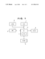
- FIG. 1 is a block diagram showing the principal circuit components of a printer according to a first embodiment of the present invention
- FIG. 2 is a timing chart showing the driving sequence of a printhead
- FIGS. 3A , 3 B are diagrams showing the relationship between an array of nozzles of a printhead and an array of printed dots;
- FIG. 4 is a diagram showing the array of data in a print buffer according to an example of the prior art
- FIG. 5 is a block diagram showing the principal circuit components of a transfer circuit according to the first embodiment of the present invention.
- FIG. 6 is a timing chart showing the operation of a transfer circuit according to the first embodiment
- FIGS. 7A to 7C are diagrams showing data arrays at a transfer source and transfer destination in the first embodiment
- FIG. 8 is a diagram showing an array of data in a print buffer
- FIGS. 9A , 9 B are diagrams showing data arrays in a transverse-to-longitudinal conversion
- FIG. 10 is a block diagram showing the principal circuit components of a transfer circuit according to the second embodiment of the present invention.
- FIG. 11 is a timing chart showing the operation of a transfer circuit according to the second embodiment.
- the printer of this embodiment is one which drives a printhead in accordance with the sequence illustrated in the timechart of FIG. 2 , and the printhead is arranged as shown in FIG. 3(A) and forms dots in an array of the kind shown in FIG. 3B by a single driving cycle of the printhead.
- FIG. 1 is a block diagram showing the principal circuit components of a circuit for controlling the printer according to the first embodiment of the present invention.
- the arrangement of FIG. 1 includes a CPU 1 , a ROM 2 , a parallel interface (PIF) 3 , a printer control integrated circuit (PC) 4 , a RAM 5 and a printhead 6 .
- the printer control IC 4 has a transfer circuit (TC) 7 .
- the CPU 1 which controls the overall operation of the printer, incorporates a timer function and input/output ports in addition to a processor section for executing programs.
- the ROM 2 stores programs executed by the CPU 1 and various data necessary for control.
- the parallel interface 3 which is connected to a host system such as a computer, receives print data and commands.
- the printer control IC 4 controls the parallel interface 3 , RAM 5 and printhead 6 based upon commands from the CPU 1 .
- the printer control IC 4 incorporates the transfer circuit 7 .
- the RAM 5 is a dynamic RAM, in which 16 bits is the width of one pass.
- the RAM 5 is used to store received datan image data and the like. As shown in FIG.
- the printhead 6 is an ink-jet printhead on which 128 ink-jet nozzles are arrayed vertically at intervals of 1/360 of an inch. Ink drops are jetted from the nozzles toward print paper while the ink-jet head is scanned horizontally relative to the print paper, thereby performing printing on the print paper.
- Data that has been received by the parallel interface 3 is stored temporarily in a receive register within the printer control IC 4 and then is stored in a receive buffer area set up in the RAM 5 .
- the CPU 1 checks to see whether or not data has been stored in the receive buffer and, if received data has been stored in the receive buffer, analyzes the received data.
- Image data that was created by expanding compressed data is stored by the CPU 1 in an editing buffer area set up in the RAM 5 .
- the transfer circuit 7 transfers the data in the editing buffer to a print buffer set up in the RAM 5 .
- FIG. 5 is a block diagram showing the principal components of the transfer circuit 7 .
- the transfer circuit 7 includes a 16-bit register 21 , a 4-bit register 22 , a transfer control circuit 23 and an address generating circuit 24 .
- the 16-bit register 21 is expressed by being divided into 4-bit registers in order to make it easier to comprehend the flow of data.
- Sixteen-bit data that has been read out of the editing buffer in RAM 5 passes through the input buffer of the printer control IC 4 and is stored in the 16-bit register 21 as input data signals ID 15 to ID 0 .
- the stored data is written to the print buffer in RAM 5 , through the output buffer of the printer control IC 4 , as output data signals OD 15 to OD 0 .
- data that has been stored in the 4-bit register 22 is output as the output signals OD 15 to OD 12 .
- Initially all “0”s are stored in the 4-bit register 22 .
- data corresponding to ID 11 to ID 8 is output as OD 11 to OD 8
- data corresponding to ID 15 to ID 12 is output as OD 7 to OD 4
- data corresponding to ID 3 to ID 0 is output as OD 3 to OD.
- the data corresponding to ID 7 to ID 4 which is among the data output by the 16-bit register 21 , is stored in the 4-bit register 22 .
- the above-described operation is controlled by the transfer control circuit 23 . Addresses of the RAM 5 when data is read out and data is written in are generated by the address generating circuit 24 .
- FIG. 6 illustrates a timing chart for when the transfer circuit 7 transfers data.
- D 15 to D 0 represent data signals of the RAM 5
- ADDRESS represents an address signal.
- R/WX represents a read/write signal, in which “1” signifies read-out and “0” signifies write.
- the R/WX signal is converted to a signal, which is suited to control of the RAM 5 , in a DRAM control circuit (not shown) within the printer control IC 4 .
- a to H of the data signals are symbols of convenience assigned in 4-bit units to facilitate and understanding of the flow of data.
- the transfer circuit When transfer starts, the transfer circuit outputs a transfer-origin address SA as an address signal and reads data A to D output of the editing buffer in RAM 5 .
- a data transfer is performed simultaneously to transfer 16 bits, i.e., two bytes, whereas addresses are provided in byte units. Data of an address SA+1, therefore, also is output at the same time.
- the transfer circuit When read-out ends, the transfer circuit outputs a transfer-destination address DA as an address signal and writes the data to the print buffer in RAM 5 .
- a write operation is performed, data is written also to the address DA+1 simultaneously in a manner similar to that of read-out.
- the “0” that was initially stored in the 4-bit register 22 is written as data D 15 to D 12 .
- FIG. 7A illustrates a data array in the editing buffer of the transfer origin
- FIG. 7B a data array in the print buffer of the transfer destination
- FIG. 7C the addresses of the respective buffers.
- One byte of data in the editing buffer signifies eight dots of image data vertically. Data obtained by rendering the eight dots of vertical image data continuous in the horizontal direction by an amount commensurate with the width of the paper makes up the editing buffer.
- the upper four dots of data are shifted in their entirety one column to the right of the diagram through the operation described earlier.
- Data is output from the editing buffer in the array (see FIG. 4 ) stored in the conventional print buffer.
- the data is stored in the print buffer in an array illustrated in FIG. 8 .
- the shaded portions in FIG. 8 represent print data printed by driving the printhead one time.
- K 1 and K 2 for example, form one byte of data, and therefore this data can be read out at one time.
- data K 3 and K 4 and data K 5 and K 6 can also be read out simultaneously in the same manner. Since only data that takes part in printing is read out when the printhead is driven, reading out 128 bits of data suffices in order to print 128 dots.
- the data is rearranged in such a manner that one word of data corresponding to a plurality of contiguous nozzles provided on the printhead of the image printing apparatus becomes one row in the print buffer.
- FIGS. 9A , 9 B and FIG. 10 A second embodiment of the present invention is illustrated in FIGS. 9A , 9 B and FIG. 10 .
- an independent data transfer circuit is provided and the arrangement of data is performed between the editing buffer and the print buffer.
- data is rearranged by improving a horizontal-to-vertical conversion circuit. The horizontal-to-vertical conversion and the method of improvement will now be described.
- the method generally employed includes providing a register having N dots in the horizontal direction and M dots in the vertical direction, reading data that is data arrayed in the horizontal direction out of N ⁇ M dots of memory, storing the data temporarily in the register and controlling the sequence of data read-out from the register, thereby writing the data to the memory as data arrayed in the vertical direction.
- FIGS. 9A , 9 B are diagrams useful in describing a horizontal-to-vertical conversion of 16 dots (horizontal direction) ⁇ 8 dots (vertical direction).
- Sixteen dots of data at the transfer source shown in FIG. 9A are read out of transfer-source addresses SA and SA+1 as two bytes of data R 1 and written to a horizontal-to-vertical conversion register in the printer control IC.
- R 2 which is data one line below R 1 , is read out of transfer-source addresses SA+H and SA+H+1. Since addresses storing data are contiguous in the horizontal direction in the case of raster data, the addresses of the data of the underlying line are spaced away by H, which corresponds to the width of the print paper.
- FIG. 10 is a block diagram showing the principal components of the transfer circuit improved in order to perform rearrangement of data at the same time as the horizontal-to-vertical conversion.
- the transfer circuit shown in FIG. 10 includes a 128-bit [16 dots (horizontal direction) ⁇ 8 dots (vertical direction)] horizontal-to-vertical conversion register 31 , and a selector 32 for extracting data, which has been stored in the horizontal-to-vertical conversion register 31 , as data arrayed in the vertical direction.
- the other functional blocks of this transfer circuit are the same as those of the transfer circuit described earlier in conjunction with FIG. 5 .
- FIG. 11 is a timing chart of the data transfer.
- 16-bit data R 1 is read out of address SA (and SA+1) in the editing buffer area of the RAM and is stored in the horizontal-to-vertical conversion register 31 .
- data R 8 By reading out data up to data R 8 in a similar manner, data of 16 dots (horizontal direction) ⁇ 8 dots (vertical direction) is prepared in the horizontal-to-vertical conversion register 31 .
- data C 1 corresponding to two rows is selected from the left by the selector 32 and is written as 2-byte data to address DA (and DA+1) in the print buffer area of the RAM. Data is written up to data C 8 in similar fashion.
- the upper four dots of data are shifted in their entirety one column to the right in a manner similar to that of the first embodiment. Furthermore, by continuously applying the horizontal-to-vertical conversion to blocks [data of 16 dots (horizontal direction) ⁇ 8 dots (vertical direction)] adjacent one after the other on the right side, it is possible to shift the upper four dots of data one column to the right over the entirety of the data commensurate with the width of the paper.
- the number of time divisions used in time-division drive is not limited to four. If one word consists of m bits and the number of time divisions is n, and if the lowest common multiple of n and m is l, data can be read out of the print buffer efficiently if l-bit data is transferred to the print buffer so as to be arranged in a single row.
- High-density, high-definition printing can be achieved especially if these embodiments of the invention employ ink-jet printing technology using means (e.g., an electrothermal transducer or laser beam mechanism) for generating thermal energy as the energy utilized to discharge ink, wherein a change in the state of the ink is brought about by this thermal energy.
- means e.g., an electrothermal transducer or laser beam mechanism
- air bubbles can be formed in the fluid (ink) in one-to-one correspondence with the drive signals. Due to growth and contraction of the air bubbles, the fluid (ink) is jetted via an orifice so as to form at least one droplet. If the drive signal has the form of a pulse, growth and contraction of the air bubbles can be made to take place rapidly and in appropriate fashion. This is preferred since it will be possible to achieve fluid (ink) discharge exhibiting excellent response.
- a print head of the full-line type having a length corresponding to the maximum width of the printing medium capable of being printed on by the printing apparatus
- the print head is not limited to one of the cartridge type, in which the print head itself is integrally provided with an ink tank.
- the print head may be of the replaceable tip-type, in which the electrical connection to the apparatus proper and the supply of ink from the apparatus proper can be achieved by mounting the head on the apparatus proper.
- the printing apparatus described above be additionally provided with print head recovery means and auxiliary means.
- print head capping means cleaning means, pressurizing or suction means, preheating means comprising an electrothermal transducer, a heating element separate from this transducer or a combination of the transducer and the heating element, and a pre-discharge mode for performing a discharge of ink separate from a discharge for printing.
- the printing mode of the printing apparatus is not limited to a printing mode solely for the mainstream colors such as black.
- the apparatus adopted can be one equipped with at least one print head for a plurality of different colors or one full-color print head using mixed colors, through it is desired that this be achieved by a print head having an integrated structure or by a combination of a plurality of print heads.
- the ink used may be one which solidifies at room temperature or lower, one which softens at room temperature or one which is a liquid at room temperature.
- temperature control is performed in such a manner that ink viscosity will fall within a stable ink jetting range by adjusting the temperature of the ink itself so as to fall within a temperature range of no less than 30° C. to no greater than 70° C. Accordingly, it will suffice to use an ink liquefied when the printing signal is applied.
- ink which solidifies when left standing but which is liquefied by application of heat ink which is liquefied for the first time by thermal energy, such as an ink liquefied by application of thermal energy conforming to a printing signal and jetted as a liquid ink, or ink which has already begun to solidify at the moment it reaches the printing medium, can be applied to the present invention.
- Such inks may be used in a form in which they oppose the electrothermal transducer in a state in which they are held as a liquid or solid in the recesses or through-holes of a porous sheet, as described in Japanese Patent Application Laid-Open Nos. 54-56847 and 60-71260.
- the most effective method of dealing with these inks is the above-described method of film boiling.
- the printing apparatus of the invention may take on the form of an apparatus that is an integral part of or separate from an image output terminal of information processing equipment such as a computer, a copier in combination with a reader or the like, or a facsimile machine having a transmitting/receiving function.
- information processing equipment such as a computer, a copier in combination with a reader or the like, or a facsimile machine having a transmitting/receiving function.
- the present invention can be applied to a system constituted by a plurality of devices (e.g., a host computer, interface, reader, printer, etc.) or to an apparatus comprising a single device (e.g., a copier or facsimile machine, etc.).
- a host computer e.g., a host computer, interface, reader, printer, etc.
- an apparatus e.g., a copier or facsimile machine, etc.
- the invention is applicable also to a case where the object of the invention is attained by supplying a storage medium storing the program codes of the software for performing the functions of the foregoing embodiments to a system or an apparatus, reading the program codes with a computer (e.g., a CPU or MPU) of the system or apparatus from the storage medium, and then executing the program codes.
- a computer e.g., a CPU or MPU
- the program codes read from the storage medium implement the novel functions of the invention, and the storage medium storing the program codes constitutes the invention.
- the storage medium such as a floppy disk, hard disk, optical disk, magneto-optical disk, CD-ROM, CD-R, magnetic tape, non-volatile type memory card or ROM can be used to provide the program codes.
- the present invention covers a case where an operating system or the like running on the computer performs a part of or the entire process in accordance with the designation of program codes and implements the functions according to the embodiments.
- the present invention further covers a case where, after the program codes read from the storage medium are written in a function extension board inserted into the computer or in a memory provided in a function extension unit connected to the computer, a CPU or the like contained in the function extension board or function extension unit performs a part of or the entire process in accordance with the designation of program codes and implements the function of the above embodiments.
- a data rearranging function is combined with a horizontal-to-vertical conversion.
Landscapes
- Engineering & Computer Science (AREA)
- General Engineering & Computer Science (AREA)
- Physics & Mathematics (AREA)
- General Physics & Mathematics (AREA)
- Theoretical Computer Science (AREA)
- Record Information Processing For Printing (AREA)
- Dot-Matrix Printers And Others (AREA)
- Electronic Switches (AREA)
Applications Claiming Priority (1)
| Application Number | Priority Date | Filing Date | Title |
|---|---|---|---|
| JP10219477A JP2000043347A (ja) | 1998-08-03 | 1998-08-03 | データ処理方法及びデータ処理装置並びに画像記録装置 |
Publications (1)
| Publication Number | Publication Date |
|---|---|
| US7092115B1 true US7092115B1 (en) | 2006-08-15 |
Family
ID=16736058
Family Applications (1)
| Application Number | Title | Priority Date | Filing Date |
|---|---|---|---|
| US09/363,823 Expired - Fee Related US7092115B1 (en) | 1998-08-03 | 1999-07-30 | Data processing method, data processing apparatus and image printing apparatus |
Country Status (3)
| Country | Link |
|---|---|
| US (1) | US7092115B1 (de) |
| EP (1) | EP0978799B1 (de) |
| JP (1) | JP2000043347A (de) |
Cited By (4)
| Publication number | Priority date | Publication date | Assignee | Title |
|---|---|---|---|---|
| US20020143823A1 (en) * | 2001-01-19 | 2002-10-03 | Stevens Mark A. | Conversion system for translating structured documents into multiple target formats |
| US20050007607A1 (en) * | 2003-03-24 | 2005-01-13 | Canon Kabushiki Kaisha | Printing apparatus and printing data control method |
| US20080036801A1 (en) * | 2006-08-09 | 2008-02-14 | Fuji Xerox Co., Ltd. | Data processing device, method, storage medium storing program therefor, and signal for discharging liquid droplets, and liquid droplet discharging device |
| US9189199B2 (en) * | 2012-12-06 | 2015-11-17 | Nvidia Corporation | Folded FIFO memory generator |
Families Citing this family (9)
| Publication number | Priority date | Publication date | Assignee | Title |
|---|---|---|---|---|
| US6786420B1 (en) | 1997-07-15 | 2004-09-07 | Silverbrook Research Pty. Ltd. | Data distribution mechanism in the form of ink dots on cards |
| US6618117B2 (en) | 1997-07-12 | 2003-09-09 | Silverbrook Research Pty Ltd | Image sensing apparatus including a microcontroller |
| US6879341B1 (en) | 1997-07-15 | 2005-04-12 | Silverbrook Research Pty Ltd | Digital camera system containing a VLIW vector processor |
| US6624848B1 (en) | 1997-07-15 | 2003-09-23 | Silverbrook Research Pty Ltd | Cascading image modification using multiple digital cameras incorporating image processing |
| US6690419B1 (en) | 1997-07-15 | 2004-02-10 | Silverbrook Research Pty Ltd | Utilising eye detection methods for image processing in a digital image camera |
| US20040119829A1 (en) | 1997-07-15 | 2004-06-24 | Silverbrook Research Pty Ltd | Printhead assembly for a print on demand digital camera system |
| US7110024B1 (en) | 1997-07-15 | 2006-09-19 | Silverbrook Research Pty Ltd | Digital camera system having motion deblurring means |
| AUPQ056099A0 (en) * | 1999-05-25 | 1999-06-17 | Silverbrook Research Pty Ltd | A method and apparatus (pprint01) |
| KR102637196B1 (ko) * | 2016-03-11 | 2024-02-15 | 마크텍 가부시키가이샤 | 노즐 구동 피크전력을 저감하는 인자 타이밍 제어 방법 및 공업용 인자 장치 |
Citations (17)
| Publication number | Priority date | Publication date | Assignee | Title |
|---|---|---|---|---|
| JPS5456847A (en) | 1977-10-14 | 1979-05-08 | Canon Inc | Medium for thermo transfer recording |
| JPS55132259A (en) | 1979-04-02 | 1980-10-14 | Canon Inc | Liquid jet recording method |
| US4313124A (en) | 1979-05-18 | 1982-01-26 | Canon Kabushiki Kaisha | Liquid jet recording process and liquid jet recording head |
| US4345262A (en) | 1979-02-19 | 1982-08-17 | Canon Kabushiki Kaisha | Ink jet recording method |
| US4459600A (en) | 1978-10-31 | 1984-07-10 | Canon Kabushiki Kaisha | Liquid jet recording device |
| JPS59123670A (ja) | 1982-12-28 | 1984-07-17 | Canon Inc | インクジエツトヘツド |
| US4463359A (en) | 1979-04-02 | 1984-07-31 | Canon Kabushiki Kaisha | Droplet generating method and apparatus thereof |
| JPS59138461A (ja) | 1983-01-28 | 1984-08-08 | Canon Inc | 液体噴射記録装置 |
| JPS6071260A (ja) | 1983-09-28 | 1985-04-23 | Erumu:Kk | 記録装置 |
| US4558333A (en) | 1981-07-09 | 1985-12-10 | Canon Kabushiki Kaisha | Liquid jet recording head |
| US4723129A (en) | 1977-10-03 | 1988-02-02 | Canon Kabushiki Kaisha | Bubble jet recording method and apparatus in which a heating element generates bubbles in a liquid flow path to project droplets |
| US5084831A (en) | 1990-05-01 | 1992-01-28 | Minolta Camera Kabushiki Kaisha | Printer and printing method |
| US5222818A (en) * | 1990-08-29 | 1993-06-29 | Seiko Epson Corporation | Tape printer apparatus and control method |
| US5570464A (en) | 1992-12-25 | 1996-10-29 | Fuji Xerox Co., Ltd. | Controller for a recording apparatus |
| US5768484A (en) * | 1994-05-11 | 1998-06-16 | Canon Kabushiki Kaisha | Printing apparatus and control method therefor |
| US5838888A (en) * | 1995-12-27 | 1998-11-17 | Brother Kogyo Kabushiki Kaisha | Image recorder |
| US5927871A (en) * | 1994-07-01 | 1999-07-27 | Canon Kabushiki Kaisha | Printer having scroll print buffer and printing method |
-
1998
- 1998-08-03 JP JP10219477A patent/JP2000043347A/ja not_active Withdrawn
-
1999
- 1999-07-30 EP EP99306090A patent/EP0978799B1/de not_active Expired - Lifetime
- 1999-07-30 US US09/363,823 patent/US7092115B1/en not_active Expired - Fee Related
Patent Citations (19)
| Publication number | Priority date | Publication date | Assignee | Title |
|---|---|---|---|---|
| US4740796A (en) | 1977-10-03 | 1988-04-26 | Canon Kabushiki Kaisha | Bubble jet recording method and apparatus in which a heating element generates bubbles in multiple liquid flow paths to project droplets |
| US4723129A (en) | 1977-10-03 | 1988-02-02 | Canon Kabushiki Kaisha | Bubble jet recording method and apparatus in which a heating element generates bubbles in a liquid flow path to project droplets |
| JPS5456847A (en) | 1977-10-14 | 1979-05-08 | Canon Inc | Medium for thermo transfer recording |
| US4459600A (en) | 1978-10-31 | 1984-07-10 | Canon Kabushiki Kaisha | Liquid jet recording device |
| US4345262A (en) | 1979-02-19 | 1982-08-17 | Canon Kabushiki Kaisha | Ink jet recording method |
| US4463359A (en) | 1979-04-02 | 1984-07-31 | Canon Kabushiki Kaisha | Droplet generating method and apparatus thereof |
| JPS55132259A (en) | 1979-04-02 | 1980-10-14 | Canon Inc | Liquid jet recording method |
| US4313124A (en) | 1979-05-18 | 1982-01-26 | Canon Kabushiki Kaisha | Liquid jet recording process and liquid jet recording head |
| US4558333A (en) | 1981-07-09 | 1985-12-10 | Canon Kabushiki Kaisha | Liquid jet recording head |
| JPS59123670A (ja) | 1982-12-28 | 1984-07-17 | Canon Inc | インクジエツトヘツド |
| JPS59138461A (ja) | 1983-01-28 | 1984-08-08 | Canon Inc | 液体噴射記録装置 |
| US4608577A (en) | 1983-09-28 | 1986-08-26 | Elm Co., Ltd. | Ink-belt bubble propulsion printer |
| JPS6071260A (ja) | 1983-09-28 | 1985-04-23 | Erumu:Kk | 記録装置 |
| US5084831A (en) | 1990-05-01 | 1992-01-28 | Minolta Camera Kabushiki Kaisha | Printer and printing method |
| US5222818A (en) * | 1990-08-29 | 1993-06-29 | Seiko Epson Corporation | Tape printer apparatus and control method |
| US5570464A (en) | 1992-12-25 | 1996-10-29 | Fuji Xerox Co., Ltd. | Controller for a recording apparatus |
| US5768484A (en) * | 1994-05-11 | 1998-06-16 | Canon Kabushiki Kaisha | Printing apparatus and control method therefor |
| US5927871A (en) * | 1994-07-01 | 1999-07-27 | Canon Kabushiki Kaisha | Printer having scroll print buffer and printing method |
| US5838888A (en) * | 1995-12-27 | 1998-11-17 | Brother Kogyo Kabushiki Kaisha | Image recorder |
Cited By (6)
| Publication number | Priority date | Publication date | Assignee | Title |
|---|---|---|---|---|
| US20020143823A1 (en) * | 2001-01-19 | 2002-10-03 | Stevens Mark A. | Conversion system for translating structured documents into multiple target formats |
| US20050007607A1 (en) * | 2003-03-24 | 2005-01-13 | Canon Kabushiki Kaisha | Printing apparatus and printing data control method |
| US7679772B2 (en) * | 2003-03-24 | 2010-03-16 | Canon Kabushiki Kaisha | Printing apparatus and printing data control method effecting distributed driving of printing elements |
| US20080036801A1 (en) * | 2006-08-09 | 2008-02-14 | Fuji Xerox Co., Ltd. | Data processing device, method, storage medium storing program therefor, and signal for discharging liquid droplets, and liquid droplet discharging device |
| US8526050B2 (en) * | 2006-08-09 | 2013-09-03 | Fuji Xerox Co., Ltd. | Data processing device, method, storage medium storing program therefor, and signal for discharging liquid droplets, and liquid droplet discharging device |
| US9189199B2 (en) * | 2012-12-06 | 2015-11-17 | Nvidia Corporation | Folded FIFO memory generator |
Also Published As
| Publication number | Publication date |
|---|---|
| EP0978799A2 (de) | 2000-02-09 |
| EP0978799A3 (de) | 2004-01-02 |
| JP2000043347A (ja) | 2000-02-15 |
| EP0978799B1 (de) | 2011-12-21 |
Similar Documents
| Publication | Publication Date | Title |
|---|---|---|
| JP3571891B2 (ja) | 記録装置、記録方法及びデータ供給方法 | |
| US6705695B2 (en) | Combination of bidirectional-and unidirectional-printing using plural ink types | |
| US6371588B1 (en) | Printhead and printing apparatus using printhead | |
| US7448709B2 (en) | Printing head, image printing apparatus using the same, and control method therefor | |
| JP3308815B2 (ja) | インクジェット記録方法及びその装置 | |
| US5621440A (en) | Bidirectional recording device and method for producing consistent images | |
| EP0978799B1 (de) | Datenverarbeitungsverfahren und -vorrichtung und Bilddruckvorrichtung | |
| JPH1071730A (ja) | インクジェット記録方法及びその装置とインクジェット記録ヘッド | |
| EP0782095A2 (de) | Tintenstrahldrucker und Steuerungsverfahren | |
| EP0602582A2 (de) | Bildaufzeichnungsgerät | |
| US5692108A (en) | Odd/even stroke control for reduced video data clocking | |
| US6409299B1 (en) | Printing apparatus and printing method | |
| US6497467B2 (en) | Inkjet printer, and method and apparatus for controlling inkjet printer | |
| JPH0825693A (ja) | 印刷方法及び装置 | |
| US7126715B2 (en) | Ink jet recording apparatus and control method therefor | |
| US20040032620A1 (en) | Printing apparatus, information processing apparatus, printing system, control method for them, and program | |
| JP2001071466A (ja) | インクジェット記録装置および該装置の記録ヘッド駆動方法 | |
| JP4007179B2 (ja) | 画像処理装置と印刷装置とで分担して画像処理を行いながら印刷する印刷システム | |
| JP5343504B2 (ja) | インクジェット記録装置、画像形成システム、画像形成方法、及びプログラム | |
| JP3441868B2 (ja) | 記録装置 | |
| JP2002240370A (ja) | 記録装置及び該記録装置におけるデータ変換方法 | |
| JP2002301839A (ja) | 記録装置及び記録方法 | |
| JP2000015874A (ja) | 画像形成装置及びその制御方法 | |
| JPH09187924A (ja) | 記録方法及び記録装置並びに記録システム | |
| JPH11115165A (ja) | インクジェットプリンタ |
Legal Events
| Date | Code | Title | Description |
|---|---|---|---|
| AS | Assignment |
Owner name: CANON KABUSHIKI KAISHA, JAPAN Free format text: ASSIGNMENT OF ASSIGNORS INTEREST;ASSIGNOR:NAKATA, KAZUHIRO;REEL/FRAME:010148/0468 Effective date: 19990723 |
|
| FEPP | Fee payment procedure |
Free format text: PAYOR NUMBER ASSIGNED (ORIGINAL EVENT CODE: ASPN); ENTITY STATUS OF PATENT OWNER: LARGE ENTITY |
|
| FPAY | Fee payment |
Year of fee payment: 4 |
|
| FPAY | Fee payment |
Year of fee payment: 8 |
|
| FEPP | Fee payment procedure |
Free format text: MAINTENANCE FEE REMINDER MAILED (ORIGINAL EVENT CODE: REM.) |
|
| LAPS | Lapse for failure to pay maintenance fees |
Free format text: PATENT EXPIRED FOR FAILURE TO PAY MAINTENANCE FEES (ORIGINAL EVENT CODE: EXP.); ENTITY STATUS OF PATENT OWNER: LARGE ENTITY |
|
| STCH | Information on status: patent discontinuation |
Free format text: PATENT EXPIRED DUE TO NONPAYMENT OF MAINTENANCE FEES UNDER 37 CFR 1.362 |
|
| FP | Lapsed due to failure to pay maintenance fee |
Effective date: 20180815 |