US7123735B2 - Method and apparatus to increase acoustic separation - Google Patents
Method and apparatus to increase acoustic separation Download PDFInfo
- Publication number
- US7123735B2 US7123735B2 US09/949,832 US94983201A US7123735B2 US 7123735 B2 US7123735 B2 US 7123735B2 US 94983201 A US94983201 A US 94983201A US 7123735 B2 US7123735 B2 US 7123735B2
- Authority
- US
- United States
- Prior art keywords
- acoustic
- acoustic apparatus
- transducer
- sound
- cells
- Prior art date
- Legal status (The legal status is an assumption and is not a legal conclusion. Google has not performed a legal analysis and makes no representation as to the accuracy of the status listed.)
- Expired - Fee Related, expires
Links
Images


Classifications
-
- H—ELECTRICITY
- H04—ELECTRIC COMMUNICATION TECHNIQUE
- H04R—LOUDSPEAKERS, MICROPHONES, GRAMOPHONE PICK-UPS OR LIKE ACOUSTIC ELECTROMECHANICAL TRANSDUCERS; ELECTRIC HEARING AIDS; PUBLIC ADDRESS SYSTEMS
- H04R1/00—Details of transducers, loudspeakers or microphones
- H04R1/02—Casings; Cabinets ; Supports therefor; Mountings therein
Definitions
- the present invention relates to the field of acoustics, and more specifically, a method and apparatus to increase acoustic separation between a sound receiving transducer (such as a microphone) and a sound transmitting transducer (such as a loudspeaker).
- a sound receiving transducer such as a microphone
- a sound transmitting transducer such as a loudspeaker
- a significant problem in the design of such systems is that the microphone intended only for near-end speech also picks up the far-end speech signal, played back using a loudspeaker.
- This acoustic and vibratory coupling problem manifests itself in two ways. First, if the far-end of the communications link also has some amount of coupling (acoustic or electrical), then the potential for instability or howling exists. Second, when the unintentionally acquired far-end signal is transmitted back to the far-end party, it is received as an audible echo. This echo, when delayed by propagation through the communications network, can be extremely annoying and in severe circumstances, can render the communications channel useless.
- the acoustic coupling problem is particularly acute when the loudspeaker and microphone are located in close proximity as in the case of a desktop handsfree telephone.
- loudspeaker There are some general approaches that can reduce the coupling.
- the physical separation between loudspeaker and microphones should be as great as possible.
- Transducers can be mounted with an acoustically opaque structure inserted in the space between them.
- the loudspeaker should be oriented so that its maximal radiation (at high frequencies) is directed away from the microphones. If directional microphones are used, the nulls of the microphones can be directed toward the loudspeaker.
- Echo-cancellation techniques can be implemented in the electronics. A practical design usually employs more than one of these techniques to achieve full duplex operation.
- acoustic separation is increased in a simple way by increasing the distance between the loudspeaker and microphone.
- U.S. Pat. No. 4,378,468 issued Mar. 29, 1983 in the name of Daryl P. Braun (the Braun patent).
- the Braun patent describes an audio conference system that alleviates sound-coupled feedback by mounting the loudspeakers below the conference table (“preferably at floor level” according to the patent) while mounting the microphones above the table. While this approach does reduce acoustic coupling, its operation relies on the presence of a suitable table and it is not applicable to systems where the loudspeaker and microphone must, of necessity, be located in the same housing.
- the effective distance between transducers can be increased by exploiting acoustic diffraction. Sound tends not to propagate around obstacles, corners or edges (hence, the utility of roadside noise barriers). The obstacles create “acoustical shadows”. The residual sound that does get around an obstacle does so through the mechanism of diffraction.
- the effects of diffraction can be predicted numerically using finite element or boundary element techniques.
- the Botros patent describes an audio conference terminal housing consisting of a cylindrical section on top of an inverted conical section.
- the loudspeaker is mounted at the top of the cylinder while the microphone is mounted at the bottom of the inverted conical section to provide physical separation between the speaker and microphone.
- acoustic coupling is reduced by mounting a directional microphone such that the direction of minimum sensitivity coincides with the direction of the loudspeaker.
- U.S. Pat. No. 3,992,586 issued Nov. 16, 1976 in the name of Christopher Jaffe generates a directional loudspeaker pattern by driving two omni-directional loudspeakers out of phase. By positioning the microphone in the acoustic null zone of the resulting dipole, acoustic coupling is reduced.
- U.S. Pat. No. 4,237,339 issued Dec. 2, 1980 in the names of Bunting et al. describes a boom on which directional microphones and a loudspeaker are rigidly mounted such the microphone nulls are directed towards the loudspeaker.
- a sound receiving transducer such as a microphone
- a sound transmitting transducer such as a loudspeaker
- a method and apparatus for increasing the acoustic separation between sound receiving transducers and sound transmitting transducers, and in particular, loudspeakers and microphones in a handsfree speakerphone is disclosed. This is achieved by modifying the acoustic impedance on the surface of the housing between transducers. If the shape of the speakerphone provides a separation or barrier structure between the receiving and transmitting transmitters to achieve acoustic decoupling through diffraction, then the modification of the acoustic impedance gives additional acoustic separation.
- the invention provides a physical structure (edge or solid body) or housing which increases the acoustic separation between transmitting and receiving transducers mounted in the housing.
- a physical structure edge or solid body
- an acoustical impedance on the surface of the housing is used, to control the acoustic propagation from the transmitting to receiving transducer.
- the impedance is inductive or mass-like.
- impedance may be resistive.
- the invention can be used in conjunction with any type of microphone, directional or non-directional and with any type of loudspeaker, directional or non-directional.
- the exterior shape of the housing can take many forms; (2) different configurations of impedance conditions can be used to provide performance tailored to specific exterior shape; and (3) the use of an acoustically transparent material to cover any air-coupled surface treatments, for appearance and dust protection.
- an acoustic loss due to diffraction is obtained When used in conjunction with optimized acoustic conditions to the housing, the effect is further enhanced. Since the incorporation of an acoustic condition may require no additional parts (electronic or otherwise), this approach is inexpensive.
- the improved acoustic separation offered by the invention is useful in all application areas that employ simultaneous operation of a loudspeaker and microphone. These include hands-free telephones (conference and desktop), multimedia computer telephony terminals, interactive kiosks (such as drive-thrus), teleconferencing, and videoconferencing.
- FIG. 1 illustrates a test case speakerphone used to evaluate acoustic diffraction for reducing coupling between loudspeaker-microphone coupling
- FIG. 4 shows the calculated sound field about the cubic “speakerphone” of FIG. 1 having a controlled surface impedance on the sides at a frequency of 300 Hz;
- FIG. 5 shows the difference in contours between the sound fields of FIGS. 3 and 4 at a frequency of 300 Hz;
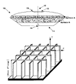
- FIG. 6 illustrates a generic celled structure providing variable acoustic impedance
- FIG. 7 illustrates the acoustic surface resistance for a simple celled structure having a cell depth of 10 cm
- FIG. 8 illustrates the side view of a simple celled structure with an overlying resistive layer
- FIG. 9 illustrates a side view of a speakerphone that exploits both diffraction and acoustic surface impedance, for enhanced separation of microphone from loudspeaker.
- FIG. 10 illustrates the sound pressure level at the microphone, for constant loudspeaker amplitude, for various surface impedance treatments.
- FIG. 1 A simple test case, illustrated in FIG. 1 , has been used to demonstrate the benefits of acoustical shadowing.
- the speakerphone housing (acting as a barrier structure) is represented by a 20 cm cube with a 6 cm square piston (representing the loudspeaker) on its top surface.
- acoustically-rigid surfaces ie: surfaces with infinite acoustic impedance
- the barrier structure serves as an acoustic surface configured to enhance diffraction loss of acoustic waves propagating by diffraction between the loudspeaker and microphone.
- the sound field generated by the piston was calculated using a boundary element technique.
- the surfaces are meshed using 1 cm square elements, giving a total of 2400 elements.
- the piston velocity was fixed (representing the loudspeaker vibration), at an amplitude of 1 m/s.
- the sound pressure level (in dB) was obtained for all points exterior to and on the surface of the speakerphone
- FIG. 2 shows the computed sound field at a signal frequency of 2000 Hz emitted by the loudspeaker.
- Contours are labeled with actual sound pressure levels (SPLs) in dB appropriate to a piston amplitude of 1 m/s.
- SPLs actual sound pressure levels
- the SPLs on the sides ie: the signal received by the microphone
- the decrease in level with distance from the piston is evident. There is a more rapid decrease, though, down the sides of the cube due to acoustic shadowing.
- a microphone measures a level of 95 dB; at the same distance but above the loudspeaker a level of about 109 dB is measured.
- the acoustic shadowing afforded by the shape of the speakerphone gives over 10 dB of decoupling between loudspeaker and microphone.
- FIG. 3 A similar calculation is shown in FIG. 3 for a frequency of 300 Hz.
- the size of the speakerphone is not as large, relative to a wavelength, as for the 2000 Hz case, and the shadowing is hence not so great.
- Contours are labeled with actual SPLs (dB) appropriate to a piston amplitude of 1 m/s.
- the loudspeaker-microphone decoupling (levels on the sides) are reduced by about 5 dB compared to levels above the loudspeaker at comparable distances.
- the acoustic separation between the loudspeaker and microphone is further increased if the acoustic surface impedance of the housing is modified.
- the results are shown in FIG. 4 . Considerable reductions in the levels on the sides are achieved compared to the rigid wall case in the previous figure. The propagation of sound down the side walls is seen to be more attenuated than for the rigid side wall case.
- FIG. 5 the difference in SPL between the results of FIGS. 3 and 4 is computed and displayed.
- This difference shows explicitly the effect of introducing a surface impedance condition.
- An additional acoustic separation of 10 dB is achieved between loudspeaker and microphone, over and above the separation obtained from the diffraction edge.
- Reductions of over 10 dB are achieved by the introduction of a surface impedance condition on the side walls. Therefore, the introduction of the surface and surface impedance on the surface results in an overall reduction of 20 dB. This is because the surface impedance discourages the propagation of acoustic energy, and when combined with the loss due to a diffractive object, the acoustic separation is enhanced.
- the velocity may be related to the gradient in sound pressure:
- a prototypal structure with a plurality of adjacent cells providing variable acoustic impedance is contemplated.
- the lateral dimensions of each cell i.e., normal to the y axis shown in the Figure
- a thin layer of a porous material such as felt, fabric, open-cell foams, or a grid with small holes
- More complicated structures can be used to tailor the frequency dependence of Z for specific applications. Different impedance functions might be desirable on different sections of a speakerphone surface. Broadband increases in acoustic separation of 10 to 20 dB are achievable for various surface impedance conditions.
- Cellular structures represent one approach to constructing impedance surfaces and are not intended to limit this invention. Any structure that provides the appropriate surface impedance will do.
- the determination of the appropriate acoustic surface impedance is governed by several factors, including the frequency range of operation, the shape of the speakerphone housing, the location of the microphone and loudspeaker in the housing, the presence of neighbouring objects (e.g., table) that scatter sound, and the availability of options for constructing surface impedance conditions. Except for the simplest of examples, numerical calculations are performed to determine the sound field around the object due to the loudspeaker for a given choice of acoustic surface impedance and distribution of impedance over the surface Finite-element or boundary-element techniques could be applied, for example.
- the response at the microphone position is determined as a function of sound frequency for different choices of acoustic surface impedance on the object.
- the choices that give the lowest overall response are the optimal choices.
- These distributions and values of surface impedance are the target impedances that a practical implementation will try to match.
- FIGS. 6 and 7 illustrate the use of celled structures to construct impedance conditions. More complicated arrangements of chambers and multiple layers can be used to obtain different acoustic surface impedances. Some examples of alternate cell geometries and distributions are disclosed in Canadian patent application 2,328,265. A compound baffle resonator is described in H. V. Fuchs and X. Zha (1995), Zeitschrift Fur Larmbekampfung, Vol. 43, 1–8. Daigle et al. describes a calculation of surface impedance for a celled structure with acoustical leakage through the cell walls. All three references are incorporated herein by reference.
- the barrier structure (or speakerphone housing) can be of virtually any shape, limited mostly by constraints of its specific application. To achieve as much acoustic separation as possible, the shape should be chosen to provide as much diffractive loss as possible between the loudspeaker and microphone positions. Practically, this means placing as large an obstruction as possible between the loudspeaker and microphone.
- Some geometric possibilities have been listed in Canadian patent application 2,292,357, incorporated herein by reference. Although this patent application addresses the different goal of improved microphone array performance, the geometries given in FIGS. 7A to 24B introduce diffractive loss, assuming a loudspeaker placement on the top of the objects. It is recognized that for some applications, the portion of housing between loudspeaker and microphone may be flat, so there would be no diffractive loss.
- FIG. 9 An example of a speakerphone design that can exploit the effects of both diffraction and acoustic surface impedance is shown in FIG. 9 .
- the housing 10 is symmetric about vertical axis 12 .
- the bottom portion 14 has the shape of an inverted cone and the top portion 16 has a section of a sphere.
- a loudspeaker 13 is located at the top of the housing and microphone 15 is located near the base (because of symmetry, only one microphone needs to be considered here).
- the surfaces in between (top and side) can have impedance conditions incorporated to enhance the acoustic separation.
- the housing has a maximum diameter of 240 mm and a base diameter of 100 mm.
- the height to the interface between top and side is 60 mm and the overall height is 90 mm.
- the loudspeaker has a diameter of 60 mm; the microphone is at a height of 8.6 mm.
- impedance conditions can be applied to the top and side surfaces.
- impedance conditions were applied to two surface regions, indicated on FIG. 9 as first surface A and second surface B.
- Surface A extends from the top/side edge roughly halfway to the top of the housing, between heights of 60 mm and 80.3 mm.
- Surface B extends from the top/side edge downward, between heights of 17.2 mm and 60 mm.
- the acoustic separation was evaluated using a boundary element calculation technique.
- the loudspeaker was assumed to have a piston-like motion with a velocity amplitude of 1 m/s.
- the speakerphone is assumed to sit on an infinite, acoustically-hard table.
- the resulting sound field subject to various surface impedance boundary conditions, was evaluated for sound frequencies between 200 Hz and 3600 Hz.
- the sound pressure level at the microphone is a measure of the acoustic coupling between loudspeaker and microphone.
- the effect of various impedance treatments is demonstrated by comparison to the rigid surface condition (for which all surfaces are acoustically rigid, i. e., infinite impedance, zero admittance).
- results of the sound pressure level (SPL) at the microphone position, for constant velocity of the piston representing the loudspeaker, are presented in FIG. 10 .
- the solid curve represents the results for acoustically rigid surfaces and is the baseline for comparision.
- the dash-dotted line represents results for a simple resistive layer, with no celled structure, having a surface resistance of 0.1 pc on surface B. Over 20 dB of increased acoustic separation is obtained between 500 Hz and 2700 Hz. This surface impedance condition, however, would be difficult to achieve.
- FIG. 10 A practical implementation using 5 cm cells and a resistive layer of 0.5 pc for surface B is represented in FIG. 10 as the dashed line. Over 10 dB of increased separation is found for a broad range of frequencies. Another embodiment is represented by the dotted line, wherein 10 cm cells on surface A and 5 cm cells on surface B both have a 0.1 pc resistive layer. Broadband increases in the acoustic separation are evident in different frequency regimes.
- Another embodiment may make use of an acoustically transparent material to cover any air-coupled surface treatments, for appearance and dust protection.
- Impedances that are inductive tend to permit the formation of air-coupled surface waves that can reduce the desired effect (e.g., the dashed and dotted curves on FIG. 10 show elevated sound pressure levels at frequencies near 600 Hz because of this effect).
- the presence of a resistive component in Z will damp out surface waves.
- the frequency responses of the loudspeaker and microphones will determine the range of frequency where increased acoustic loss is desirable.
- the size of the housing must be taken into consideration since larger housings will have much more diffractive loss at high frequencies, so the timing of the impedance is preferably geared to lower frequencies.
- the acoustic separation between loudspeaker and microphone can be increased by 10–20 dB over a broad frequency range.
- the selection of optimum surface impedance treatment, though, must be tuned to the specific application.
- the acoustic separation between loudspeaker and microphone, using 5 cm cells and a 0.5 pc resistive layer on surface B is over 10 dB between 1500 and 2000 Hz.
- Several other factors e.g., frequency response of both microphone and loudspeaker, proximity of reflecting surfaces, acoustical noise environment) must be considered.
Landscapes
- Physics & Mathematics (AREA)
- Engineering & Computer Science (AREA)
- Acoustics & Sound (AREA)
- Signal Processing (AREA)
- Soundproofing, Sound Blocking, And Sound Damping (AREA)
- Circuit For Audible Band Transducer (AREA)
Priority Applications (1)
| Application Number | Priority Date | Filing Date | Title |
|---|---|---|---|
| US09/949,832 US7123735B2 (en) | 2000-09-14 | 2001-09-12 | Method and apparatus to increase acoustic separation |
Applications Claiming Priority (2)
| Application Number | Priority Date | Filing Date | Title |
|---|---|---|---|
| US23262300P | 2000-09-14 | 2000-09-14 | |
| US09/949,832 US7123735B2 (en) | 2000-09-14 | 2001-09-12 | Method and apparatus to increase acoustic separation |
Publications (2)
| Publication Number | Publication Date |
|---|---|
| US20020044645A1 US20020044645A1 (en) | 2002-04-18 |
| US7123735B2 true US7123735B2 (en) | 2006-10-17 |
Family
ID=22873874
Family Applications (1)
| Application Number | Title | Priority Date | Filing Date |
|---|---|---|---|
| US09/949,832 Expired - Fee Related US7123735B2 (en) | 2000-09-14 | 2001-09-12 | Method and apparatus to increase acoustic separation |
Country Status (2)
| Country | Link |
|---|---|
| US (1) | US7123735B2 (fr) |
| CA (1) | CA2357253C (fr) |
Cited By (3)
| Publication number | Priority date | Publication date | Assignee | Title |
|---|---|---|---|---|
| US20040166906A1 (en) * | 2003-02-21 | 2004-08-26 | Hsiao-Wu Chen | Mobile phone with a connector capable of assembling both a microphone and a coin battery |
| US20050175189A1 (en) * | 2004-02-06 | 2005-08-11 | Yi-Bing Lee | Dual microphone communication device for teleconference |
| US20070110257A1 (en) * | 2003-07-01 | 2007-05-17 | Stephanie Dedieu | Microphone array with physical beamforming using omnidirectional microphones |
Families Citing this family (5)
| Publication number | Priority date | Publication date | Assignee | Title |
|---|---|---|---|---|
| US20060034481A1 (en) * | 2003-11-03 | 2006-02-16 | Farhad Barzegar | Systems, methods, and devices for processing audio signals |
| US8019449B2 (en) * | 2003-11-03 | 2011-09-13 | At&T Intellectual Property Ii, Lp | Systems, methods, and devices for processing audio signals |
| US7450570B1 (en) | 2003-11-03 | 2008-11-11 | At&T Intellectual Property Ii, L.P. | System and method of providing a high-quality voice network architecture |
| CN105308939B (zh) * | 2013-05-07 | 2019-04-26 | 诺基亚技术有限公司 | 减小的声学耦合 |
| DK201500810A1 (en) * | 2015-12-16 | 2017-07-03 | Bang & Olufsen As | A loudspeaker and microphone device |
Citations (17)
| Publication number | Priority date | Publication date | Assignee | Title |
|---|---|---|---|---|
| US3831710A (en) * | 1973-01-24 | 1974-08-27 | Lockheed Aircraft Corp | Sound absorbing panel |
| US3992586A (en) | 1975-11-13 | 1976-11-16 | Jaffe Acoustics, Inc. | Boardroom sound reinforcement system |
| US4078155A (en) * | 1977-01-17 | 1978-03-07 | Northern Telecom Limited | Telephone apparatus for use in a conference room |
| US4237339A (en) | 1977-11-03 | 1980-12-02 | The Post Office | Audio teleconferencing |
| US4339018A (en) * | 1978-10-27 | 1982-07-13 | Lord Corporation | Sound absorbing structure |
| US4378468A (en) | 1980-10-10 | 1983-03-29 | Darome, Inc. | Methods and apparatus for alleviating sound-coupled feedback in conference room sound systems |
| US4811402A (en) * | 1986-11-13 | 1989-03-07 | Epic Corporation | Method and apparatus for reducing acoustical distortion |
| US5121426A (en) | 1989-12-22 | 1992-06-09 | At&T Bell Laboratories | Loudspeaking telephone station including directional microphone |
| US5452265A (en) | 1991-07-01 | 1995-09-19 | The United States Of America As Represented By The Secretary Of The Navy | Active acoustic impedance modification arrangement for controlling sound interaction |
| US5896461A (en) | 1995-04-06 | 1999-04-20 | Coherent Communications Systems Corp. | Compact speakerphone apparatus |
| US6016346A (en) * | 1997-10-21 | 2000-01-18 | 3Com Corporation | Low-profile speakerphone with downward oriented microphone configuration |
| US6041125A (en) | 1996-08-15 | 2000-03-21 | Mitsubishi Jukogyo Kabushiki Kaishal | Active acoustic wall |
| CA2292357A1 (fr) | 1998-12-18 | 2000-06-18 | Michael R. Stinson | Structure de diffraction de reseau de microphones |
| US6085865A (en) * | 1998-02-26 | 2000-07-11 | Societe Nationale D'etude Et De Construction De Moteurs D'aviation "Snecma" | Soundproofing panel and method of producing said panel |
| CA2328265A1 (fr) | 1999-12-16 | 2001-06-16 | James G. Ryan | Structures a ondes de surface a couplage par air pour la modification d'un champ acoustique |
| US6290022B1 (en) * | 1998-02-05 | 2001-09-18 | Woco Franz-Josef Wolf & Co. | Sound absorber for sound waves |
| US6374120B1 (en) * | 1999-02-16 | 2002-04-16 | Denso Corporation | Acoustic guide for audio transducers |
-
2001
- 2001-09-12 CA CA2357253A patent/CA2357253C/fr not_active Expired - Fee Related
- 2001-09-12 US US09/949,832 patent/US7123735B2/en not_active Expired - Fee Related
Patent Citations (18)
| Publication number | Priority date | Publication date | Assignee | Title |
|---|---|---|---|---|
| US3831710A (en) * | 1973-01-24 | 1974-08-27 | Lockheed Aircraft Corp | Sound absorbing panel |
| US3992586A (en) | 1975-11-13 | 1976-11-16 | Jaffe Acoustics, Inc. | Boardroom sound reinforcement system |
| US4078155A (en) * | 1977-01-17 | 1978-03-07 | Northern Telecom Limited | Telephone apparatus for use in a conference room |
| US4237339A (en) | 1977-11-03 | 1980-12-02 | The Post Office | Audio teleconferencing |
| US4339018A (en) * | 1978-10-27 | 1982-07-13 | Lord Corporation | Sound absorbing structure |
| US4378468A (en) | 1980-10-10 | 1983-03-29 | Darome, Inc. | Methods and apparatus for alleviating sound-coupled feedback in conference room sound systems |
| US4811402A (en) * | 1986-11-13 | 1989-03-07 | Epic Corporation | Method and apparatus for reducing acoustical distortion |
| US5121426A (en) | 1989-12-22 | 1992-06-09 | At&T Bell Laboratories | Loudspeaking telephone station including directional microphone |
| US5452265A (en) | 1991-07-01 | 1995-09-19 | The United States Of America As Represented By The Secretary Of The Navy | Active acoustic impedance modification arrangement for controlling sound interaction |
| US5896461A (en) | 1995-04-06 | 1999-04-20 | Coherent Communications Systems Corp. | Compact speakerphone apparatus |
| US6041125A (en) | 1996-08-15 | 2000-03-21 | Mitsubishi Jukogyo Kabushiki Kaishal | Active acoustic wall |
| US6016346A (en) * | 1997-10-21 | 2000-01-18 | 3Com Corporation | Low-profile speakerphone with downward oriented microphone configuration |
| US6290022B1 (en) * | 1998-02-05 | 2001-09-18 | Woco Franz-Josef Wolf & Co. | Sound absorber for sound waves |
| US6085865A (en) * | 1998-02-26 | 2000-07-11 | Societe Nationale D'etude Et De Construction De Moteurs D'aviation "Snecma" | Soundproofing panel and method of producing said panel |
| CA2292357A1 (fr) | 1998-12-18 | 2000-06-18 | Michael R. Stinson | Structure de diffraction de reseau de microphones |
| US6374120B1 (en) * | 1999-02-16 | 2002-04-16 | Denso Corporation | Acoustic guide for audio transducers |
| CA2328265A1 (fr) | 1999-12-16 | 2001-06-16 | James G. Ryan | Structures a ondes de surface a couplage par air pour la modification d'un champ acoustique |
| US6491134B2 (en) * | 1999-12-16 | 2002-12-10 | National Research Council Of Canada | Air-coupled surface wave structures for sound field modification |
Non-Patent Citations (3)
| Title |
|---|
| "A new hybrid passive/active noise absorption system", Beyene et al., J. Acoust. Soc. Am.,101(3), Mar. 1997, pp. 1512-1515. |
| "Experiments on surface waves over a model impedence plane using acoustical pulses", Gillies A. Daigle et al., J. Acoust. Soc. Am. , 99 (4), Apr. 1996, pp. 1993-2005. |
| "Wirkungsweise und auslegungshinweise fur verbund-platten-resonatoren", H.V. Fuchs & X. Zha., Zeitschrift Fur Larmbekamp 43 (1996). |
Cited By (5)
| Publication number | Priority date | Publication date | Assignee | Title |
|---|---|---|---|---|
| US20040166906A1 (en) * | 2003-02-21 | 2004-08-26 | Hsiao-Wu Chen | Mobile phone with a connector capable of assembling both a microphone and a coin battery |
| US7203528B2 (en) * | 2003-02-21 | 2007-04-10 | Benq Corporation | Mobile phone with a connector capable of assembling both a microphone and a coin battery |
| US20070110257A1 (en) * | 2003-07-01 | 2007-05-17 | Stephanie Dedieu | Microphone array with physical beamforming using omnidirectional microphones |
| US7840013B2 (en) * | 2003-07-01 | 2010-11-23 | Mitel Networks Corporation | Microphone array with physical beamforming using omnidirectional microphones |
| US20050175189A1 (en) * | 2004-02-06 | 2005-08-11 | Yi-Bing Lee | Dual microphone communication device for teleconference |
Also Published As
| Publication number | Publication date |
|---|---|
| CA2357253C (fr) | 2011-06-07 |
| US20020044645A1 (en) | 2002-04-18 |
| CA2357253A1 (fr) | 2002-03-14 |
Similar Documents
| Publication | Publication Date | Title |
|---|---|---|
| US7366310B2 (en) | Microphone array diffracting structure | |
| CN100593351C (zh) | 阵列装置以及便携式终端 | |
| US8111838B2 (en) | Conferencing apparatus for echo cancellation using a microphone arrangement | |
| EP1685741B1 (fr) | Agencements d'émetteurs soniques | |
| US12223938B2 (en) | Acoustic wave attenuator for an electronic device | |
| CA2522896A1 (fr) | Methode et appareil pour une transduction sonore presentant une interference minimale provenant d'un bruit de fond et un rayonnement acoustique local minimal | |
| JP2001516548A (ja) | 埋込型単一指向性マイクロホン | |
| JP2008252625A (ja) | 指向性スピーカシステム | |
| JP2859527B2 (ja) | ラウドスピーカ組立体 | |
| EP0951797A1 (fr) | Dispositif antibruit | |
| US7123735B2 (en) | Method and apparatus to increase acoustic separation | |
| CN101442695B (zh) | 麦克风系统、声音输入设备和制造所述系统和设备的方法 | |
| EP0852891B1 (fr) | Configuration de montage d'un microphone antibruit | |
| US6275580B1 (en) | Teleconferencing device having acoustic transducers positioned to improve acoustic echo return loss | |
| CA2241708C (fr) | Telephone a haut-parleur et microphone connexe | |
| EP1121832A1 (fr) | Dispositif de regulation des bruits pour un microphone suppresseur de bruit monte sur un bras | |
| US6491134B2 (en) | Air-coupled surface wave structures for sound field modification | |
| US6788791B2 (en) | Delay network microphones with harmonic nesting | |
| CN1905600B (zh) | 消除免持电话通信中声学回声的方法和装置 | |
| KR102686767B1 (ko) | 이어 패드, 이어머프 부품 및 이어폰 | |
| Kataoka et al. | A microphone-array configuration for AMNOR Adaptive microphone-array system for noise reduction | |
| US12413895B2 (en) | Loudspeaker assembly and hand-held device | |
| JP2006266968A (ja) | 送受波器 | |
| JPH0320200B2 (fr) |
Legal Events
| Date | Code | Title | Description |
|---|---|---|---|
| AS | Assignment |
Owner name: NATIONAL RESEARCH COUNCIL OF CANADA, CANADA Free format text: ASSIGNMENT OF ASSIGNORS INTEREST;ASSIGNORS:RYAN, JAMES G.;STINSON, MICHAEL R.;REEL/FRAME:012163/0466 Effective date: 20010910 |
|
| FPAY | Fee payment |
Year of fee payment: 4 |
|
| REMI | Maintenance fee reminder mailed | ||
| LAPS | Lapse for failure to pay maintenance fees | ||
| STCH | Information on status: patent discontinuation |
Free format text: PATENT EXPIRED DUE TO NONPAYMENT OF MAINTENANCE FEES UNDER 37 CFR 1.362 |
|
| STCH | Information on status: patent discontinuation |
Free format text: PATENT EXPIRED DUE TO NONPAYMENT OF MAINTENANCE FEES UNDER 37 CFR 1.362 |
|
| FP | Lapsed due to failure to pay maintenance fee |
Effective date: 20141017 |