US7156150B2 - Two-roll casting device - Google Patents
Two-roll casting device Download PDFInfo
- Publication number
- US7156150B2 US7156150B2 US10/555,564 US55556405A US7156150B2 US 7156150 B2 US7156150 B2 US 7156150B2 US 55556405 A US55556405 A US 55556405A US 7156150 B2 US7156150 B2 US 7156150B2
- Authority
- US
- United States
- Prior art keywords
- scrap
- trough
- housing
- collection
- metal strip
- Prior art date
- Legal status (The legal status is an assumption and is not a legal conclusion. Google has not performed a legal analysis and makes no representation as to the accuracy of the status listed.)
- Expired - Lifetime
Links
- 238000005266 casting Methods 0.000 title claims abstract description 102
- 239000002184 metal Substances 0.000 claims abstract description 73
- 238000009434 installation Methods 0.000 claims abstract description 50
- 238000007599 discharging Methods 0.000 claims abstract description 4
- 238000007789 sealing Methods 0.000 claims description 74
- 238000011282 treatment Methods 0.000 claims description 14
- 239000000155 melt Substances 0.000 claims description 12
- 238000006073 displacement reaction Methods 0.000 claims description 8
- 238000000034 method Methods 0.000 claims description 8
- 230000007246 mechanism Effects 0.000 claims description 5
- 230000000977 initiatory effect Effects 0.000 claims description 4
- 238000007790 scraping Methods 0.000 claims description 2
- 238000007493 shaping process Methods 0.000 claims description 2
- 230000035515 penetration Effects 0.000 abstract 1
- 239000007789 gas Substances 0.000 description 12
- 230000001681 protective effect Effects 0.000 description 12
- 238000004519 manufacturing process Methods 0.000 description 6
- 239000004576 sand Substances 0.000 description 4
- 238000009966 trimming Methods 0.000 description 3
- 229910000831 Steel Inorganic materials 0.000 description 2
- QVGXLLKOCUKJST-UHFFFAOYSA-N atomic oxygen Chemical compound [O] QVGXLLKOCUKJST-UHFFFAOYSA-N 0.000 description 2
- 230000004888 barrier function Effects 0.000 description 2
- 238000010438 heat treatment Methods 0.000 description 2
- 229910052760 oxygen Inorganic materials 0.000 description 2
- 239000001301 oxygen Substances 0.000 description 2
- 230000036961 partial effect Effects 0.000 description 2
- 230000008569 process Effects 0.000 description 2
- 238000005096 rolling process Methods 0.000 description 2
- 239000010959 steel Substances 0.000 description 2
- 229910000975 Carbon steel Inorganic materials 0.000 description 1
- 230000002411 adverse Effects 0.000 description 1
- 230000015572 biosynthetic process Effects 0.000 description 1
- 230000008859 change Effects 0.000 description 1
- 238000006243 chemical reaction Methods 0.000 description 1
- 238000009749 continuous casting Methods 0.000 description 1
- 238000010924 continuous production Methods 0.000 description 1
- 230000009977 dual effect Effects 0.000 description 1
- 239000013013 elastic material Substances 0.000 description 1
- 239000002657 fibrous material Substances 0.000 description 1
- 238000007654 immersion Methods 0.000 description 1
- 230000006872 improvement Effects 0.000 description 1
- 238000011017 operating method Methods 0.000 description 1
- 230000003647 oxidation Effects 0.000 description 1
- 238000007254 oxidation reaction Methods 0.000 description 1
- 230000001590 oxidative effect Effects 0.000 description 1
- 230000002829 reductive effect Effects 0.000 description 1
- 230000000717 retained effect Effects 0.000 description 1
- 238000011144 upstream manufacturing Methods 0.000 description 1
- 239000002759 woven fabric Substances 0.000 description 1
Images



Classifications
-
- B—PERFORMING OPERATIONS; TRANSPORTING
- B22—CASTING; POWDER METALLURGY
- B22D—CASTING OF METALS; CASTING OF OTHER SUBSTANCES BY THE SAME PROCESSES OR DEVICES
- B22D11/00—Continuous casting of metals, i.e. casting in indefinite lengths
- B22D11/06—Continuous casting of metals, i.e. casting in indefinite lengths into moulds with travelling walls, e.g. with rolls, plates, belts, caterpillars
- B22D11/0622—Continuous casting of metals, i.e. casting in indefinite lengths into moulds with travelling walls, e.g. with rolls, plates, belts, caterpillars formed by two casting wheels
-
- B—PERFORMING OPERATIONS; TRANSPORTING
- B22—CASTING; POWDER METALLURGY
- B22D—CASTING OF METALS; CASTING OF OTHER SUBSTANCES BY THE SAME PROCESSES OR DEVICES
- B22D11/00—Continuous casting of metals, i.e. casting in indefinite lengths
- B22D11/06—Continuous casting of metals, i.e. casting in indefinite lengths into moulds with travelling walls, e.g. with rolls, plates, belts, caterpillars
- B22D11/0637—Accessories therefor
- B22D11/0697—Accessories therefor for casting in a protected atmosphere
-
- B—PERFORMING OPERATIONS; TRANSPORTING
- B22—CASTING; POWDER METALLURGY
- B22D—CASTING OF METALS; CASTING OF OTHER SUBSTANCES BY THE SAME PROCESSES OR DEVICES
- B22D11/00—Continuous casting of metals, i.e. casting in indefinite lengths
- B22D11/12—Accessories for subsequent treating or working cast stock in situ
- B22D11/128—Accessories for subsequent treating or working cast stock in situ for removing
- B22D11/1287—Rolls; Lubricating, cooling or heating rolls while in use
-
- B—PERFORMING OPERATIONS; TRANSPORTING
- B22—CASTING; POWDER METALLURGY
- B22D—CASTING OF METALS; CASTING OF OTHER SUBSTANCES BY THE SAME PROCESSES OR DEVICES
- B22D15/00—Casting using a mould or core of which a part significant to the process is of high thermal conductivity, e.g. chill casting; Moulds or accessories specially adapted therefor
- B22D15/005—Casting using a mould or core of which a part significant to the process is of high thermal conductivity, e.g. chill casting; Moulds or accessories specially adapted therefor of rolls, wheels or the like
-
- C—CHEMISTRY; METALLURGY
- C22—METALLURGY; FERROUS OR NON-FERROUS ALLOYS; TREATMENT OF ALLOYS OR NON-FERROUS METALS
- C22C—ALLOYS
- C22C33/00—Making ferrous alloys
- C22C33/02—Making ferrous alloys by powder metallurgy
- C22C33/0257—Making ferrous alloys by powder metallurgy characterised by the range of the alloying elements
- C22C33/0264—Making ferrous alloys by powder metallurgy characterised by the range of the alloying elements the maximum content of each alloying element not exceeding 5%
- C22C33/0271—Making ferrous alloys by powder metallurgy characterised by the range of the alloying elements the maximum content of each alloying element not exceeding 5% with only C, Mn, Si, P, S, As as alloying elements, e.g. carbon steel
Definitions
- the invention relates to a two-roll casting installation with two casting rolls which rotate in opposite directions about horizontal axes, with a casting gap for forming and discharging a thin cast metal strip, with a sealed housing which has a base and surrounds the conveying path for the metal strip which leaves the casting gap from a vertical casting direction into an approximately horizontal conveying direction, with diverter devices for diverting the metal strip within this housing, and with a displaceable scrap collection container for removing scrap and scale produced from the two-roll casting installation.
- the invention also relates to a method for initiating a casting process using the two-roll casting device according to the invention.
- Two-roll casting installations are used to produce metal strips, preferably steel strips, with a large strip width and with a strip thickness of less than 10 mm in a continuous casting process.
- metal strips preferably steel strips
- strip thickness of less than 10 mm
- WO 02/11924 has already disclosed a two-roll casting installation of the generic type. It comprises two casting rolls which rotate in opposite directions about horizontal axes of rotation and, together with side plates which can be placed onto the end sides of the casting rolls, form a melt space and a casting gap, out of which a cast metal strip is discharged vertically downward.
- the cast metal strip is diverted into the horizontal, so as to form a hanging loop, and then fed to one or more further treatment devices.
- the hot metal strip passes through a sealed chamber with a protective gas atmosphere, which substantially prevents oxidation processes at the surface of the metal strip. All the openings in this chamber are provided with sealed gates or locks.
- the sealed chamber also comprises a space which is open toward the casting rolls for receiving a movable scrap carriage, which, via a lock system which can be flooded with protective gas, can be moved into a receiving position beneath the two casting rolls for the scrap and scale produced and can be removed from this position.
- a lock system which can be flooded with protective gas
- To manipulate the scrap carriage large lock gates have to be opened and large spaces accommodating the scrap carriage have to be flooded with protective gas.
- complex sealing systems have to be installed for the large lock gates.
- WO 02/11924 has disclosed a pivotable guide flap for the cast metal strip, which in an operating position assists with diverting the metal strip into the horizontal and toward a pinch-roll stand and, in a retracted position, allows vertical discharging of a piece of the strand into the scrap bucket.
- a solution of this type is also known from WO 01/23120.
- EP-B 726 112 and WO 01/39914 have disclosed two-roll casting installations of the generic type, in which the cast metal strip is passed through an insulated chamber without integrated base region.
- the base region is formed by a scrap bucket which can be pressed vertically onto the end sides of the side walls of the insulated chamber and rests on a displaceable scrap carriage such that it can be raised and lowered.
- a seal is provided between the side walls of the insulated chamber and the edges of the scrap bucket, by means of which seal the insulated chamber is closed off in a substantially gastight manner.
- a further object of the invention is to design the two-roll casting installation in such a way that it is possible to remove the collected scrap or scale with very little ingress of air into the insulated housing.
- the emptying device comprises at least one collection trough for receiving the scrap, at least one support for this collection trough on a carrying frame or on the housing, which allows actuation of the collection trough between a closed position and an open position, at least one adjustment drive for displacing the collection trough in order to allow it to be emptied, and any seals that may be required in order to prevent external air from entering the housing.
- An expedient embodiment consists in the fact that the collection trough for the scrap is designed such that it can be displaced between a closed position and an open position and is coupled to an adjustment drive, and that the housing is assigned a sealing element for sealing a gap between the housing and the collection trough in the closed position.
- the collection trough may be of single-piece or multipiece design, and the emptying can be effected by a translational movement, preferably of a single-piece design, or by a pivoting movement about one or more pivot axes, preferably of a multipiece design.
- the collection trough is assigned an adjustment drive, which may be formed by an actuable pressure-medium cylinder or by at least one driven running-mechanism wheel.
- the sealing elements which act between the housing and the collection trough are expediently secured to the housing and are designed so that they can be pressed onto the collection trough in the closed position of the latter. This prevents damage to the sealing element during manipulation of the collection trough and in particular during unloading of the scrap.
- a preferred configuration of the sealing element consists in the fact that the sealing element comprises a sealing ring, which can move relative to the housing and relative to the collection trough, can be pressed onto the collection trough, is supported by a displacement element acting on the housing and secured to it, and is coupled to a controllable movement device.
- the displacement element may be formed, for example, by a bellows or another elastic element which permits longitudinal stretching
- the controllable movement device may be formed, for example, by a pressure-medium cylinder which is articulatedly mounted on the housing.
- the collection trough prefferably has a running mechanism, and for this running mechanism to be assigned a running track, in particular rails.
- this running track it is possible, preferably simultaneously with the movement toward the closed position, over the last part of the movement path, to reduce the distance between the collection trough and the housing or the sealing element secured to the housing to such an extent that a closed, sealing position is reached automatically or with a short movement path of the sealing element.
- the collection trough has sliding elements, and these sliding elements are assigned a stationary slideway.
- the slideway By adopting a suitable configuration of the slideway, it is possible, at the same time as the movement toward the closed position, over the last part of the movement path, to reduce the distance between the collection trough and the housing or the sealing element secured to the housing to such an extent that a closed, sealing position is reached.
- a clearing board for scraping off the collected scrap in the collection trough is arranged on the housing at a distance from the collection trough.
- the distance between the clearing board and the collection trough is selected in such a way that pieces of scrap do not become jammed between the stationary clearing board and the collection trough.
- the clearing board may in this case rest in a sliding manner on the collection trough. There is provision for it to be possible to retract the clearing board transversely with respect to the translational movement of the collection trough, for emergency situations.
- the collection trough comprises a receiving region for receiving the scrap, which may be of various configurations.
- the receiving region for the scrap may be formed by a planar surface, the associated clearing board having a straight clearing edge which is arranged at a short distance from the surface of the receiving region or slides along it.
- the receiving region for the scrap may also be shaped as a trough-like recess, this recess preferably being present on three sides of the collection trough, while on the fourth side, at which the emptying of the collection trough takes place, the trough-like recess runs out substantially horizontally.
- a sealing element assigned to the housing is designed such that in the open position of the collection trough it can be pressed onto the movable scrap collection container in its receiving position.
- a further improvement to the sealing can be achieved if, while the operation of moving the collection trough is ongoing, a seal is ensured between the movable scrap collection container and the housing on at least three sides. This is achieved by a multipart sealing element.
- a sealing element assigned to the housing is designed in such a manner that while the collection trough is opening, it can be pressed continuously or with subsections onto the movable scrap collection container in its receiving position.
- the housing is assigned a single encircling sealing element which is designed in such a manner that in the closed position of the collection trough it can be pressed onto the latter and in the open position of the collection trough it can be pressed onto the movable scrap collection container.
- the housing is assigned two sealing elements which are independent of one another, one of these sealing elements being designed such that it can be pressed onto the collection trough in the closed position of the latter, while the second sealing element is designed such that it can be pressed onto the movable scrap collection container.
- the two sealing elements are preferably secured concentrically with respect to one another on the outer wall of the housing and can be actuated independently of one another.
- a treatment chamber with a strip conveying device for example a roller table, and optionally further strip treatment devices for the metal strip, for example a temperature compensation furnace upstream of a rolling stand, adjoin the housing which is flooded with protective gas, in which case the base of this treatment chamber is formed by at least one emptiable collection container for scale and optionally scrap, for example trimming scrap from a strip-trimming installation.
- the collection container is preferably designed as a collection trough with a closure device and may be formed, for example, by a funnel-shaped collection hopper with a closure flap.
- One or more receiving positions for a movable scrap collection container are provided beneath the collection containers.
- the movable scrap collection container is equipped with a movement controller which allows it to be moved in a controlled way into all receiving positions below the conveying path for the metal strip.
- the receiving positions are fixed, for example, by sliding electrical contacts or light barriers.
- the invention proposes an operating method for initiating a casting process, which allows the discharge and removal of a first piece of the cast metal strip from the installation, this piece having been produced in a starting phase without steady-state conditions of the two-roll casting installation and therefore not meeting the quality demands imposed on the product to be produced.
- the invention proposes in particular scrap manipulation which as far as possible minimizes the ingress of external air during this starting phase but also allows the subsequent production steps and removal of scrap from the installation with the ingress of air minimized.
- the actual starting procedure can be effected in various ways.
- metal melt is introduced into the melt space up to an operating casting level, and the metal strip starts to be discharged during this filling operation.
- This operation can begin with the casting rolls stationary or already in rotation.
- the width of the casting gap may also deviate from an operating casting gap width.
- the filling operation in the melt space, the casting rate and the casting gap width can follow a predetermined start-up curve.
- the first piece which is produced under casting conditions which are not steady-state conditions, is detached under the force of the weight of this strip section itself. In this case too, the casting rate and the casting gap width can follow a profile curve.
- a preferred starting method for the casting process in a two-roll casting installation without taking the scrap economics into account has already been described in detail in Austrian patent application AT-A 1367/2002 and should be considered an integral part of the present application.
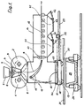
- FIG. 1 shows a longitudinal section through a two-roll casting installation with an emptying device according to the invention
- FIG. 2 shows an embodiment of a sealing element between the housing and a collection trough or a scrap collection container
- FIG. 3 shows a first operating situation of the two-roll casting installation according to the invention
- FIG. 4 shows a second operating situation of the two-roll casting installation according to the invention
- FIG. 5 shows a third operating situation of the two-roll casting installation according to the invention
- FIG. 6 shows a further embodiment of a sealing element between the housing and a collection trough or a scrap collection container.
- FIG. 1 diagrammatically depicts a two-roll casting installation of the type according to the invention for the continuous production of a steel strip.
- the core part of the two-roll casting installation for forming the metal strip comprises two driven casting rolls 1 , 2 which rotate in opposite directions about horizontal axes and, together with two side plates 3 , only one of which is illustrated in FIG. 1 , form a melt space 4 for receiving metal melt which is fed into the melt space 4 from a tundish 5 via an immersion pipe 6 , where it forms a melt bath.
- the melt space 4 is closed off in a substantially airtight manner by means of a covering 7 , which allows a protective gas atmosphere to be maintained above the melt bath.
- the two cooled casting rolls 1 , 2 and the side plates 3 which bear against the end sides of the casting rolls form a casting gap 8 , from which the metal melt, which has previously solidified in the form of strand shells at the casting-roll surfaces, is discharged in the vertical casting direction as a cast metal strip 9 before being diverted into a horizontal conveying direction and fed by a pinch-roll stand 10 to various further processing devices in the direction indicated by the arrow.
- a pivotable diverter device 11 in runner form is provided beneath the casting gap 8 to divert the metal strip 9 into the horizontal conveying direction, which diverter device can be pivoted from a thread-in position, which is indicated by solid lines and in which the metal strip 9 is diverted toward the pinch-roll stand 10 , into a substantially vertical retracted position, which is indicated by dot-dashed lines. In this retracted position, strip sections as are produced in particular at the start and end of casting can be disposed of vertically downward as scrap.
- the conveying path for the metal strip 9 from the exit from the casting gap 8 to entry into the pinch-roll stand 10 is surrounded by a housing 13 , which is usually formed by sheet-metal walls with a refractory lining on their inner side.
- seals (not shown), as described in Austrian patent application AT-A 303/2002, are provided between the wall of the housing and the casting rolls 1 , 2 or the side plates 3 .
- a treatment chamber 14 which is likewise flooded with protective gas and in which the metal strip is conveyed onward on a roller table 15 and fed to further treatment devices (not shown in more detail), adjoins the housing 13 in a sealing manner.
- These further treatment devices may, for example, comprise heat treatments of the metal strip in a strip edge heating device or in a temperature compensation furnace or mechanical treatments of the metal strip in a strip trimming installation or in rolling stands.
- An emptying device 17 forms the base 16 of the housing 13 and in a region below the casting gap 8 is formed by a collection trough 18 , in which short strip sections which drop down having been separated out of the production process and any scale which drops off the cast metal strip are collected.
- the first piece of the cast metal strip formed at the start of casting during a starting phase which lacks steady state conditions does not satisfy the product requirements and is therefore at least partially not diverted into the horizontal conveying direction for further processing toward the first pinch-roll stand, but rather is discharged directly vertically downward into the collection trough 18 .
- the collection trough 18 has a tub-shaped receptacle for the scrap and is equipped with a running mechanism 19 which comprises running wheels 20 which roll along a running track 21 formed by a horizontal longitudinal carrier or a rail.
- the collection trough 18 can be displaced from a closed position, represented by solid lines, for receiving the scrap into a retracted, open position, indicated by dot-dashed lines, by means of an actuable movement device 22 which is linked to the collection trough and is formed by a pressure-medium cylinder 23 with a long stroke.
- the scrap which has been collected is removed from the collection trough by a clearing board 27 , which is arranged at a short distance above the collection trough 18 , transversely with respect to its direction of displacement, and this scrap is then transferred into a scrap collection container 25 which is provided below.
- the scrap collection container is placed in a traveling frame 28 and can be manipulated independently of the ongoing production process at the two-roll casting installation.
- the running wheels 20 may be equipped with a running drive (not shown in more detail).
- an adjustable sealing element 30 is arranged between these components.
- One possible embodiment is diagrammatically depicted in partial section in FIG. 2 .
- FIG. 2 shows a partial region of the lower end of the housing 13 and the collection trough 18 for the scrap positioned at a distance beneath it.
- An encircling bearing flange 32 for the sealing element 30 to be secured to is welded to the outer wall 31 of the housing or its load-bearing structure.
- a sealing ring 34 which is placed and secured in a sealing ring bearing frame 35 , bears against a metal support plate 33 of the collection trough 18 , which forms a sealing surface.
- a displacement element 37 for the sealing ring bearing frame 35 which permits a change in length, is formed by a bellows 36 and is secured in a sealing manner on one side to the bearing flange 32 and on the other side to the sealing ring bearing frame 35 .
- Synchronously controllable movement devices 38 which are formed by pressure-medium cylinders 39 , are arranged at a plurality of positions, distributed over the circumference of the housing 13 , between the bearing flange 32 and the sealing ring bearing frame 35 , by means of which movement devices 38 the sealing ring 34 can be pressed onto the metal support plate 33 of the collection trough 18 in the closed position of the collection trough or lifted off the latter when the collection trough is to be moved into the open position in order to be emptied.
- telescopic metal protection sheets 40 are secured both to the bearing flange 32 and to the sealing ring bearing frame 35 between the bellows and the outer wall 31 of the housing 13 .
- the sealing ring 34 is made from an elastic material, such as woven fabric, fiber material or the like. However, it may also be replaced by a different type of seal, such as for example a sand seal, in which case the metal support plate on the collection trough is designed as a tub-shaped receptacle for sand and instead of the sealing ring a metal sealing plate is submerged in this bed of sand in the closed position of the collection trough.
- the height of the metal sealing plate can once again be adjusted by means of a displacement element, such as a pressure-medium cylinder.
- the same seal can be used to produce not just a sealing connection between the housing and the collection trough, but also, in the open position of the collection trough, a sealing connection between the housing 13 and the movable scrap collection container 25 , as illustrated in FIGS. 3–5 .
- FIG. 6 like FIG. 2 , illustrates a further embodiment of a seal which is as efficient as possible between the housing 13 and the collection trough 18 arranged beneath it as well as the scrap collection container 25 .
- Two sealing elements 30 , 30 a which can be actuated independently of one another, are secured to the outer wall of the collection trough 13 , the sealing element 30 , as has been described with reference to FIG. 2 , producing a sealed connection to the collection trough 18 , and the further sealing element 30 a , which is arranged concentrically with respect to this sealing element 30 , producing a sealed connection to the scrap collection container 25 .
- the structure of the two sealing elements 30 , 30 a is identical and corresponds to the embodiments shown in FIG. 2 . Any other equivalent sealing element can equally be used.
- a sealing connection is retained during all operating situations, either with respect to the collection trough 18 or, on at least three sides, with respect to the scrap collection container 25 .
- FIGS. 3 to 5 illustrate the arrangement according to the invention of the housing 13 , the collection trough 18 and the scrap collection container 25 with respect to one another in three characteristic operating situations.
- the collection trough 18 is in this case in the shape of a tub, double-walled and of water-cooled design and is filled with sand.
- FIG. 3 illustrates an operating situation as occurs in the start-up phase of the casting process.
- the scrap trough 18 has been moved into the open position, so that the housing 13 is open toward the scrap collection container 25 and pieces of strip which drop down fall directly into the scrap collection container.
- the sealing element 30 which surrounds the housing 13 on all sides bears, by way of its sealing ring 34 , against the metal support plate 33 of the scrap collection container 25 and is in its lowest position of use, closing off the gap space between the housing and the scrap collection container in a sealing manner.
- FIG. 4 illustrates an operating situation in which the collection trough 18 adopts the closed position below the housing 13 and the sealing element 30 bears against the metal support plate 33 of the collection trough 18 by means of its sealing ring 34 .
- Any scrap and scale which drop down are collected in the collection trough until the scrap collection container 25 has returned to its receiving position below the closed collection trough after it has been emptied. While the collection trough 18 is in this closed position, the scrap collection container 25 can at any time briefly be moved out of the installation to be emptied without impairing the production process running on the two-roll casting installation.
- FIG. 5 illustrates the operating situation in which collected scrap is being emptied out of the collection trough 18 into the scrap collection container.
- the sealing element 30 which closes off the gap between the housing 13 and the collection trough 18 in an airtight manner, has been raised into a release position
- the collection trough 18 is moved into its open position by means of a transverse movement and at the same time scrap which has collected in the collection trough is pushed into the scrap collection container by means of the clearing board 27 .
- the sealing element 30 is placed on the scrap collection container.
- a sealing element which is segmented along its circumferential extent, it is possible for individual segments to be placed on the scrap collection container immediately after the collection trough has been moved away.
- the treatment chamber 14 which immediately follows the housing 13 on the conveying path of the cast metal strip can likewise be flooded with protective gas.
- the base of this treatment chamber 14 below the strip conveying device 15 , which is formed by a roller table on which the still-hot metal strip is being conveyed, is equipped with two emptiable, funnel-shaped collection containers 41 with closure flaps 43 , which can be opened and closed by pressure-medium cylinders 42 .
- a scrap collection container 25 equipped with a movement controller can be moved in sequence both to the emptying position below the closed collection trough 18 and to individual emptying positions below the closure flaps 43 which are opened after the scrap collection container 25 has adopted the respective emptying position.
- the individual emptying positions are defined by sliding contacts or light barriers.
Landscapes
- Engineering & Computer Science (AREA)
- Mechanical Engineering (AREA)
- Chemical & Material Sciences (AREA)
- Materials Engineering (AREA)
- Metallurgy (AREA)
- Organic Chemistry (AREA)
- Continuous Casting (AREA)
- Processing Of Solid Wastes (AREA)
- Moulding By Coating Moulds (AREA)
- Refinement Of Pig-Iron, Manufacture Of Cast Iron, And Steel Manufacture Other Than In Revolving Furnaces (AREA)
- Casting Or Compression Moulding Of Plastics Or The Like (AREA)
Applications Claiming Priority (3)
| Application Number | Priority Date | Filing Date | Title |
|---|---|---|---|
| ATA678/2003 | 2003-05-06 | ||
| AT0067803A AT412539B (de) | 2003-05-06 | 2003-05-06 | Zweiwalzengiesseinrichtung |
| PCT/EP2004/004264 WO2004098814A1 (de) | 2003-05-06 | 2004-04-22 | Zweiwalzengiesseinrichtung |
Publications (2)
| Publication Number | Publication Date |
|---|---|
| US20060118270A1 US20060118270A1 (en) | 2006-06-08 |
| US7156150B2 true US7156150B2 (en) | 2007-01-02 |
Family
ID=32932021
Family Applications (1)
| Application Number | Title | Priority Date | Filing Date |
|---|---|---|---|
| US10/555,564 Expired - Lifetime US7156150B2 (en) | 2003-05-06 | 2004-04-22 | Two-roll casting device |
Country Status (9)
| Country | Link |
|---|---|
| US (1) | US7156150B2 (de) |
| EP (1) | EP1620217B1 (de) |
| KR (1) | KR101209825B1 (de) |
| CN (1) | CN100534668C (de) |
| AT (2) | AT412539B (de) |
| AU (1) | AU2004235896B2 (de) |
| DE (1) | DE502004002305D1 (de) |
| MX (1) | MXPA05011789A (de) |
| WO (1) | WO2004098814A1 (de) |
Cited By (6)
| Publication number | Priority date | Publication date | Assignee | Title |
|---|---|---|---|---|
| KR100829909B1 (ko) | 2006-12-26 | 2008-05-19 | 주식회사 포스코 | 스케일 슬레이지 및 운행 방법 |
| US20090236067A1 (en) * | 2008-03-19 | 2009-09-24 | Nucor Corporation | Strip casting apparatus with casting roll positioning |
| US20090288798A1 (en) * | 2008-05-23 | 2009-11-26 | Nucor Corporation | Method and apparatus for controlling temperature of thin cast strip |
| US20110020972A1 (en) * | 2009-07-21 | 2011-01-27 | Sears Jr James B | System And Method For Making A Photovoltaic Unit |
| US20120090357A1 (en) * | 2010-10-19 | 2012-04-19 | Takahide Nakamura | Glass film ribbon production method and glass film ribbon production apparatus |
| CN106536086A (zh) * | 2014-07-21 | 2017-03-22 | 株式会社Posco | 金属纤维的产品化系统 |
Families Citing this family (9)
| Publication number | Priority date | Publication date | Assignee | Title |
|---|---|---|---|---|
| US20090236068A1 (en) * | 2008-03-19 | 2009-09-24 | Nucor Corporation | Strip casting apparatus for rapid set and change of casting rolls |
| KR101657775B1 (ko) * | 2014-10-08 | 2016-09-20 | 주식회사 포스코 | 금속 섬유 배출장치 |
| CN105710320B (zh) * | 2015-12-31 | 2018-01-19 | 安泰科技股份有限公司 | 非晶带材制备过程中废带的收集装置 |
| CN106735030B (zh) * | 2017-01-17 | 2020-01-10 | 中冶华天工程技术有限公司 | 一种用于铸坯热送系统的氧化铁皮收集装置及方法 |
| CN110312581B (zh) * | 2017-02-23 | 2021-05-18 | 普锐特冶金技术日本有限公司 | 薄板连续铸造装置 |
| CN110170626B (zh) * | 2019-06-20 | 2024-02-06 | 中冶赛迪工程技术股份有限公司 | 一种铸轧预冷浇注装置 |
| CN111299529A (zh) * | 2020-03-20 | 2020-06-19 | 上海二十冶建设有限公司 | 一种超薄带铸辊安装方法 |
| CN112157232B (zh) * | 2020-09-16 | 2021-10-19 | 东北大学 | 一种多弧度导卫板 |
| CN114309516B (zh) * | 2021-12-29 | 2023-12-05 | 深圳市以凡泰科技有限公司 | 镍钛合金高效高通量连铸装置及方法 |
Citations (8)
| Publication number | Priority date | Publication date | Assignee | Title |
|---|---|---|---|---|
| EP0726112A1 (de) | 1995-02-10 | 1996-08-14 | Ishikawajima-Harima Heavy Industries Co., Ltd. | Giessen eines Stahlbandes |
| WO2001039914A1 (en) | 1999-12-01 | 2001-06-07 | Ishikawajima-Harima Heavy Industries Company Limited | Casting steel strip |
| WO2002011924A1 (en) | 2000-08-08 | 2002-02-14 | Ishikawajima-Harima Heavy Industries Company Limited | Continuous strip casting device and method of use thereof |
| US20040040689A1 (en) | 1999-09-24 | 2004-03-04 | Heinrich Marti | Strip casting machine for production of a metal strip |
| AT411822B (de) | 2002-09-12 | 2004-06-25 | Voest Alpine Ind Anlagen | Verfahren und vorrichtung zum starten eines giessvorganges |
| US20040244940A1 (en) * | 2002-08-12 | 2004-12-09 | Isamu Nakayama | Dual roll casting machine |
| US20050077024A1 (en) | 2002-02-27 | 2005-04-14 | Gerald Hohenbichler | Device for continuously casting molten metals |
| US20050236134A1 (en) * | 2002-07-10 | 2005-10-27 | Alfredo Poloni | Continuous casting plant with a deflecting device for metallic strips and deflecting method |
-
2003
- 2003-05-06 AT AT0067803A patent/AT412539B/de not_active IP Right Cessation
-
2004
- 2004-04-22 CN CNB2004800124028A patent/CN100534668C/zh not_active Expired - Lifetime
- 2004-04-22 MX MXPA05011789A patent/MXPA05011789A/es active IP Right Grant
- 2004-04-22 EP EP04728773A patent/EP1620217B1/de not_active Expired - Lifetime
- 2004-04-22 DE DE502004002305T patent/DE502004002305D1/de not_active Expired - Lifetime
- 2004-04-22 US US10/555,564 patent/US7156150B2/en not_active Expired - Lifetime
- 2004-04-22 AT AT04728773T patent/ATE347951T1/de not_active IP Right Cessation
- 2004-04-22 AU AU2004235896A patent/AU2004235896B2/en not_active Ceased
- 2004-04-22 WO PCT/EP2004/004264 patent/WO2004098814A1/de not_active Ceased
-
2005
- 2005-11-04 KR KR1020057021053A patent/KR101209825B1/ko not_active Expired - Fee Related
Patent Citations (9)
| Publication number | Priority date | Publication date | Assignee | Title |
|---|---|---|---|---|
| EP0726112A1 (de) | 1995-02-10 | 1996-08-14 | Ishikawajima-Harima Heavy Industries Co., Ltd. | Giessen eines Stahlbandes |
| US20040040689A1 (en) | 1999-09-24 | 2004-03-04 | Heinrich Marti | Strip casting machine for production of a metal strip |
| WO2001039914A1 (en) | 1999-12-01 | 2001-06-07 | Ishikawajima-Harima Heavy Industries Company Limited | Casting steel strip |
| WO2002011924A1 (en) | 2000-08-08 | 2002-02-14 | Ishikawajima-Harima Heavy Industries Company Limited | Continuous strip casting device and method of use thereof |
| US20020036073A1 (en) | 2000-08-08 | 2002-03-28 | Osamu Takeuchi | Continuous strip casting device and method of use thereof |
| US20050077024A1 (en) | 2002-02-27 | 2005-04-14 | Gerald Hohenbichler | Device for continuously casting molten metals |
| US20050236134A1 (en) * | 2002-07-10 | 2005-10-27 | Alfredo Poloni | Continuous casting plant with a deflecting device for metallic strips and deflecting method |
| US20040244940A1 (en) * | 2002-08-12 | 2004-12-09 | Isamu Nakayama | Dual roll casting machine |
| AT411822B (de) | 2002-09-12 | 2004-06-25 | Voest Alpine Ind Anlagen | Verfahren und vorrichtung zum starten eines giessvorganges |
Cited By (10)
| Publication number | Priority date | Publication date | Assignee | Title |
|---|---|---|---|---|
| KR100829909B1 (ko) | 2006-12-26 | 2008-05-19 | 주식회사 포스코 | 스케일 슬레이지 및 운행 방법 |
| US20090236067A1 (en) * | 2008-03-19 | 2009-09-24 | Nucor Corporation | Strip casting apparatus with casting roll positioning |
| US8002016B2 (en) | 2008-03-19 | 2011-08-23 | Nucor Corporation | Strip casting apparatus with casting roll positioning |
| US20090288798A1 (en) * | 2008-05-23 | 2009-11-26 | Nucor Corporation | Method and apparatus for controlling temperature of thin cast strip |
| US20110020972A1 (en) * | 2009-07-21 | 2011-01-27 | Sears Jr James B | System And Method For Making A Photovoltaic Unit |
| US7888158B1 (en) | 2009-07-21 | 2011-02-15 | Sears Jr James B | System and method for making a photovoltaic unit |
| US20120090357A1 (en) * | 2010-10-19 | 2012-04-19 | Takahide Nakamura | Glass film ribbon production method and glass film ribbon production apparatus |
| US8656737B2 (en) * | 2010-10-19 | 2014-02-25 | Nippon Electric Glass Co., Ltd. | Glass film ribbon production method and glass film ribbon production apparatus |
| CN106536086A (zh) * | 2014-07-21 | 2017-03-22 | 株式会社Posco | 金属纤维的产品化系统 |
| US10076782B2 (en) | 2014-07-21 | 2018-09-18 | Posco | Metal fiber manufacturing system |
Also Published As
| Publication number | Publication date |
|---|---|
| KR101209825B1 (ko) | 2012-12-07 |
| US20060118270A1 (en) | 2006-06-08 |
| AU2004235896B2 (en) | 2009-12-03 |
| ATE347951T1 (de) | 2007-01-15 |
| ATA6782003A (de) | 2004-09-15 |
| DE502004002305D1 (de) | 2007-01-25 |
| CN100534668C (zh) | 2009-09-02 |
| WO2004098814A1 (de) | 2004-11-18 |
| KR20060011852A (ko) | 2006-02-03 |
| MXPA05011789A (es) | 2006-01-26 |
| EP1620217B1 (de) | 2006-12-13 |
| CN1784279A (zh) | 2006-06-07 |
| AT412539B (de) | 2005-04-25 |
| EP1620217A1 (de) | 2006-02-01 |
| AU2004235896A1 (en) | 2004-11-18 |
Similar Documents
| Publication | Publication Date | Title |
|---|---|---|
| US7156150B2 (en) | Two-roll casting device | |
| KR100416668B1 (ko) | 스틸스트립주조방법및주조장치 | |
| EP2289649B1 (de) | Bandgießmaschine zur schnellen Einstellung und Änderung von Gießrollen | |
| CN100446894C (zh) | 生产钢带的方法 | |
| CN1217758C (zh) | 连续浇注钢带的方法和浇注钢带的装置 | |
| AU2001283674B2 (en) | Continuous strip casting device and method of use thereof | |
| AU2001283674A1 (en) | Continuous strip casting device and method of use thereof | |
| US20070158046A1 (en) | Continuously casting steel strip | |
| CN1399583A (zh) | 制造金属带的带材连铸机及其控制方法 | |
| EP0124541B1 (de) | Behandlung von metall | |
| KR20020063886A (ko) | 박형 강 스트립 제조 방법 및 장치 | |
| US7140418B2 (en) | Method and device for the evacuation of casting wastes | |
| WO2004091827A1 (en) | Casting steel strip |
Legal Events
| Date | Code | Title | Description |
|---|---|---|---|
| AS | Assignment |
Owner name: VOEST-ALPINE INDUSTRIEANLAGENBAU GMBH & CO., AUSTR Free format text: ASSIGNMENT OF ASSIGNORS INTEREST;ASSIGNORS:ZAHEDI, MICHAEL;STEPANEK, THOMAS;HOHENBICHLER, GERALD;AND OTHERS;REEL/FRAME:017328/0961 Effective date: 20051115 |
|
| STCF | Information on status: patent grant |
Free format text: PATENTED CASE |
|
| FEPP | Fee payment procedure |
Free format text: PAYOR NUMBER ASSIGNED (ORIGINAL EVENT CODE: ASPN); ENTITY STATUS OF PATENT OWNER: LARGE ENTITY |
|
| FPAY | Fee payment |
Year of fee payment: 4 |
|
| FPAY | Fee payment |
Year of fee payment: 8 |
|
| MAFP | Maintenance fee payment |
Free format text: PAYMENT OF MAINTENANCE FEE, 12TH YEAR, LARGE ENTITY (ORIGINAL EVENT CODE: M1553) Year of fee payment: 12 |
|
| AS | Assignment |
Owner name: SIEMENS VAI METALS TECHNOLOGIES GMBH, AUSTRIA Free format text: MERGER;ASSIGNOR:SIEMENS VAI METALS TECHNOLOGIES GMBH & CO;REEL/FRAME:050114/0767 Effective date: 20100630 Owner name: SIEMENS VAI METALS TECHNOLOGIES GMBH & CO, AUSTRIA Free format text: CHANGE OF NAME;ASSIGNOR:VOEST-ALPINE INDUSTRIEANLAGENBAU GMBH & CO;REEL/FRAME:050076/0824 Effective date: 19991106 Owner name: PRIMETALS TECHNOLOGIES AUSTRIA GMBH, AUSTRIA Free format text: CHANGE OF NAME;ASSIGNOR:SIEMENS VAI METALS TECHNOLOGIES GMBH;REEL/FRAME:050077/0297 Effective date: 20150107 |