US7156199B2 - Motorcycle - Google Patents
Motorcycle Download PDFInfo
- Publication number
- US7156199B2 US7156199B2 US10/780,279 US78027904A US7156199B2 US 7156199 B2 US7156199 B2 US 7156199B2 US 78027904 A US78027904 A US 78027904A US 7156199 B2 US7156199 B2 US 7156199B2
- Authority
- US
- United States
- Prior art keywords
- supporting member
- seat supporting
- exhaust pipe
- lower seat
- seat
- Prior art date
- Legal status (The legal status is an assumption and is not a legal conclusion. Google has not performed a legal analysis and makes no representation as to the accuracy of the status listed.)
- Expired - Fee Related, expires
Links
Images




Classifications
-
- B—PERFORMING OPERATIONS; TRANSPORTING
- B62—LAND VEHICLES FOR TRAVELLING OTHERWISE THAN ON RAILS
- B62K—CYCLES; CYCLE FRAMES; CYCLE STEERING DEVICES; RIDER-OPERATED TERMINAL CONTROLS SPECIALLY ADAPTED FOR CYCLES; CYCLE AXLE SUSPENSIONS; CYCLE SIDECARS, FORECARS, OR THE LIKE
- B62K11/00—Motorcycles, engine-assisted cycles or motor scooters with one or two wheels
- B62K11/02—Frames
- B62K11/04—Frames characterised by the engine being between front and rear wheels
Definitions
- This invention relates to a motorcycle.
- a main frame extends in a rearward direction from a head pipe and a rear arm for supporting a rear wheel attached at the rear of the main frame for an up and down swinging movement.
- an exhaust pipe of an engine extends in a rearward direction around a region below the engine and a muffler connected to the exhaust pipe disposed at a higher position than the rear wheel.
- the muffler connected to the exhaust pipe as described above is usually attached directly to a seat rail or directly to a cross member of the seat rail.
- the muffler connected to the exhaust pipe is usually attached directly to the seat rail or the cross member of the seat rail, so that the seat disposed on the seat rail is affected by heat from the exhaust pipe and the muffler. Therefore, other components besides the seat rail are required, for preventing heat transmission from the exhaust pipe and the muffler to the seat, causing a problem of a complex structure, an increased number of parts and increased costs.
- an advantage of the present invention is to provide a motorcycle in which a seat is supported with a simple structure, heat transmission is mitigated, the number of parts is reduced and the cost is lowered.
- this invention is arranged as indicated below.
- the invention is a motorcycle including a body frame, a seat, an engine mounted on the body frame, and an exhaust pipe connected to the engine and disposed below the seat.
- the motorcycle also includes a seat supporting member provided extending in a rearward direction from a body and the seat supporting member is made up of an upper seat supporting member with the seat in place, and a lower seat supporting member connected to and separated in a downward direction from the upper seat supporting member.
- the lower seat supporting member is configured as a plate-like member in a shape to cover a region above at least the exhaust pipe. This arrangement allows heat from the exhaust pipe to be blocked by the lower seat supporting member and a space between the lower seat supporting member and the upper seat supporting member, so that heat transmission from the exhaust pipe to the seat is prevented. Therefore, no heat insulating material or the like is required to be used to prevent heat transmission from the exhaust pipe to the seat.
- the lower seat supporting member has a structure in which a frame portion for supporting the seat opens in a downward direction, therefore it shuts off heat transmission from the exhaust pipe as well as supporting the seat, and the exhaust pipe can be cooled down by the outside air.
- a rear arm is supported on the body through a pair of left and right rear cushions for an up and down swinging movement.
- the lower seat supporting member extends to a position where it is interposed between the rear cushions and the exhaust pipe, to cover the exhaust pipe. This arrangement can prevent heat transmission from the exhaust pipe to the rear cushions reliably.
- the lower seat supporting member has a shape to cover the muffler in addition to the exhaust pipe, therefore heat transmission from the exhaust pipe and the muffler can be shut off.
- the lower seat supporting member covers a portion of the exhaust pipe where a catalyst is disposed inside, therefore heat transmission from the portion of the catalyst at high temperatures can be shut off.
- the upper seat supporting member is configured as a plate-like member, and the seat supporting member is made up of the upper seat supporting member and the lower seat supporting member in a hollow shape. This arrangement allows the hollow section to serve as an insulating space, thereby preventing heat transmission from the exhaust pipe to the seat more reliably.
- FIG. 1 is a side view of a motorcycle.
- FIG. 2 is a side view showing an arrangement of a rear arm, a rear cushion and an exhaust pipe.
- FIG. 3 is a plan view showing an arrangement of a main frame, a rear arm and rear cushions.
- FIG. 4 is a side view showing an arrangement of the rear arm and the rear cushion.
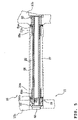
- FIG. 5 is a sectional view taken along a line V—V of FIG. 4 .
- FIG. 6 is a sectional view taken along a line VI—VI of FIG. 4 .
- FIG. 7 is a sectional view taken along a line VII—VII of FIG. 4 .
- FIG. 8 is a sectional view taken along a line VIII—VIII of FIG. 2 .
- FIG. 9 is a sectional view taken along a line IX—IX of FIG. 2 .
- FIG. 10 is a side view of a seat back stay unit.
- FIG. 11 is a plan view of the seat back stay unit.
- FIG. 12 is a side view of a lower back stay.
- FIG. 13 is a front view of the lower back stay.
- FIG. 1 is a side view of a motorcycle.
- FIG. 2 is a side view showing an arrangement of a rear arm, a rear cushion and an exhaust pipe.
- FIG. 3 is a plan view showing an arrangement of a main frame, a rear arm and rear cushions.
- FIG. 4 is a side view showing an arrangement of the rear arm and the rear cushion.
- FIG. 5 is a sectional view taken along a line V—V of FIG. 4 .
- FIG. 6 is a sectional view taken along a line VI—VI of FIG. 4 .
- FIG. 7 is a sectional view taken along a line VII—VII of FIG. 4 .
- FIG. 8 is a sectional view taken along a line VIII—VIII of FIG. 2 .
- FIG. 9 is a sectional view taken along a line IX—IX of FIG. 2 .
- FIG. 10 is a side view of a seat back stay unit.
- FIG. 11 is a plan view of the seat back stay unit.
- FIG. 12 is a side view of a lower back stay.
- FIG. 13 is a front view of the lower back stay.
- the motorcycle 1 of this embodiment includes a body frame 2 , a body cover 3 covering the body frame 2 , an engine 4 suspended from the body frame 2 , a front wheel 5 , a rear wheel 6 , a fuel tank 7 , a seat 8 and the like.
- a body includes the body frame 2 and the engine 4 suspended from the body frame 2 .
- the body frame 2 mainly includes a head pipe 1 , a main frame 15 , in the shape of an inverse letter L in profile, extending in a downward direction towards the rear from the head pipe 11 , and a seat back stay 90 or a seat supporting member extending in the rearward direction from the rear upper part of the main frame 15 for placing a seat 8 .
- the head pipe 11 is provided with a front fork 12 supported for steering movement, a handle 13 connected to the front fork 12 at the top and the front wheel 5 suspended at the lower end of the front fork 12 .
- the engine 4 is mounted to the main frame 15 , and a radiator 14 is disposed at the front of the main frame 15 and in front of the engine 4 .
- the engine 4 is a four-cylinder, four-stroke engine, and an intake duct 40 and an intake box 41 are disposed in an upward direction of a cylinder 4 a of the engine 4 , by which intake air is introduced to a carburetor 42 disposed behind the cylinder 4 a.
- the fuel tank 7 is disposed on the main frame 15 .
- the fuel tank 7 extends in a downward direction at the rear bottom and a fuel pump 43 is disposed inside the extension 7 a .
- fuel pump 43 Upon operation of the fuel pump 43 , fuel is supplied to the carburetor 42 through a supply hose 43 a and excessive fuel is returned from a return hose 43 b to the fuel tank 7 .
- the four exhaust pipes 44 are connected to the cylinder 4 a of the engine 4 at the front side.
- the four exhaust pipes 44 are assembled into two pipes below the engine 4 , which pipes extend around a region below the engine 4 .
- These two exhaust pipes 44 are assembled into one pipe behind the engine 4 .
- a muffler 45 is connected to the assembled exhaust pipe 44 .
- the muffler 45 is disposed at a higher position than a rear wheel axle, and thus, it is fixed to the seat back stay 90 at a higher position than the rear wheel 6 .
- the four exhaust pipes and the muffler are respectively denoted by reference numerals 44 and 45 , but the exhaust pipes 44 include the muffler 45 , which means the pipes or the paths allow exhaust gas to be directed into the atmosphere from the cylinder 4 a of the engine 4 .
- the main frame 15 is a wide rectangular body with a hollow section, consisting of left and right horizontal sections 15 a extending in a rearward direction from the head pipe 11 , and vertical sections 15 b extending in a downward direction from the rear portions of the horizontal sections 15 a , and supporting a load applied to the seat 8 .
- a rear arm 21 is attached to the vertical sections 15 b of the main frame 15 for an up and down swinging movement about a pivot shaft 22 , as shown in FIGS. 1–4 , which is supported by rear cushions 23 on the body.
- the rear wheel 6 is supported on the rear arm 21 at the rear end.
- a chain 26 is stretched over a sprocket 24 provided on an output shaft 4 b of the engine 4 and a sprocket 25 provided on an axle 6 a of the rear wheel 6 . Power of the engine 4 is transmitted to the rear wheel 6 by the chain 26 .
- the chain 26 as shown in FIG. 3 , is disposed on the left side with respect to a longitudinal body center line L 1 .
- the rear arm 21 consists of a central connecting section 21 a , a pair of forward side-sections 21 b extending in a forward direction from the connecting section 21 a in a forked relation, and a pair of rear side-sections 21 c extending in a rearward direction from the connecting section 21 a in a forked relation.
- a cross member 27 is welded between the pair of forward side-sections 21 b , as shown in FIG. 3 .
- the rear arm 21 is formed with a downwardly projecting reinforcement convex section 21 d extending between the forward side-section 21 b and the rear side-section 21 c .
- the reinforcement convex section 21 d has a triangular shape in profile projecting to a lowermost position at the central connecting section 21 a .
- a chain through opening 21 e is opened in the projecting section for the passage of the chain 26 .
- the rear arm 21 having the downwardly projecting reinforcement convex section 21 d , can be provided with the reinforcement convex section 21 d without taking into account interference with the pair of left and right rear cushions 23 . Therefore a rear arm 21 with sufficient rigidity can be adopted.
- the pair of forward side-sections 21 b of the rear arm 21 are each set against the inside surfaces of the vertical sections 15 b of the main frame 15 .
- the pivot shaft 22 is inserted therein from the vertical section 15 b on the right side through a boss 60 .
- a bolt 63 is fastened to the pivot shaft from the vertical section 15 b on the left side through a boss 61 and a lock 62 .
- the pair of forward side-sections 21 b of the rear arm 21 are supported on the pivot shaft 22 through bushes 64 a , 64 b and bearings 65 a , 65 b , respectively, and the cross member 27 is supported on the pivot shaft 22 through a collar 66 .
- the rear arm 21 is supported on the body through the pair of left and right rear cushions 23 .
- the pair of left and right rear cushions 23 as shown in FIGS. 1–4 each includes a link 70 supported on the body, a cushion 71 having opposite ends 71 a , 71 b supported between one end 70 a of the link 70 and the rear arm 21 , and a rod 72 having opposite ends 72 a , 72 b supported between the other end 70 b of the link 70 and the rear arm 21 .
- Cushion performance is improved by the construction of the pair of left and right rear cushions 23 .
- One end 71 b of the cushion 71 is supported through a bush 74 and a bearing 75 on a bolt 73 screwed in the upper part 21 f of the rear arm 21 .
- One end 72 b of the rod 72 is supported through a bush 77 and a bearing 78 on a bolt 76 screwed in the upper part 21 f of the rear arm 21 .
- the link 70 is supported through a bearing 80 on a support shaft 79 mounted to the boss sections 15 c of the main frame 15 .
- One end 71 a of the cushion 71 is supported through a bush 82 and a bearing 83 on a bolt 81 screwed in one end 70 a of the link 70 .
- One end 72 a of the rod 72 is supported through a bearing 85 on a bolt 84 screwed in the other end 70 b of the link 70 .
- the lower end of the rear cushion 23 and that of the rod 72 are supported on the upper part 21 f of the rear arm 21 , and the rear cushion 23 and the rod 72 can be disposed compact without interference with other members.
- a rear fender 86 is attached to the upper part 21 f of the rear arm 21 at a position further rearward than the cushion 71 .
- the cushion 71 is disposed to the rear of the rod 72 and the cushion 71 can be removed from the rear of the body, facilitating adjustment of the cushion.
- the links 70 disposed on the left and right sides, as shown in FIG. 7 are supported on a common support shaft 79 supported on the body, enabling reduction in the number of parts as a result of use of common parts, and compact arrangement without interference with other members.
- the rear arm 21 of this embodiment is supported on the body through the pair of left and right cushions 23 and the exhaust pipe 44 is disposed extending in an upward direction from below the engine 4 and passing through a space behind the pivot shaft 22 and between the pair of forward side-sections 21 b of the rear arm 21 , and as shown in FIG. 8 , through a space between the pair of left and right rear cushions 23 .
- the exhaust pipe 44 is disposed passing through a space between the pair of left and right rear cushions 23 . Therefore the exhaust pipe does not interfere with the rear arm 21 and the rear cushions 23 , so that a rear arm 21 of a large rigidity can be adopted.
- the rigidity can be set at any given value, the degree of freedom of designing a motorcycle can be increased and a large bank angle can be secured easily.
- the exhaust pipe 44 as shown in FIGS. 3 and 8 , is disposed on the longitudinal body center line L 1 . Therefore the rear arm 21 need not be formed in the shape of a relief so as not to interfere with the exhaust pipe. Thus, a rear arm 21 of a larger rigidity can be adopted, the rigidy can be set at any given value, and the degree of freedom of designing a motorcycle can be increased.
- the pair of left and right rear cushions 23 and the exhaust pipe 44 are offset from the longitudinal body center line L 1 by a distance D 1 in the direction opposite to the chain 26 for transmitting power of the engine 4 to the rear wheel.
- One rear cushion arranged on the same side as the chain 26 of the pair of left and right rear cushions 23 is disposed closer to the center line compared with the other rear cushion.
- the pair of left and right rear cushions 23 and the exhaust pipe 44 can be disposed compact without interference with the chain 26 .
- the rear cushions 23 and the exhaust pipe 44 are disposed in a crossing relation, and if they are disposed such that their overlapping area in profile becomes smaller, heat transmission from the exhaust pipe 44 to the rear cushions 23 is mitigated. In this way, the thermal influence of the exhaust pipe 44 on the rear cushions 23 can be decreased depending on the arrangement of the rear cushions 23 and the exhaust pipe 44 .
- the rear end 44 a of the exhaust pipe 44 , and the muffler 45 connected to the rear end 44 are attached to the seat back stay 90 or the seat supporting member, and the seat 8 is disposed on the seat back stay 90 .
- the seat back stay 90 includes a lower seat back stay 91 or a lower seat supporting member and an upper seat back stay 92 or an upper seat supporting member joined together in one body.
- the lower seat back stay 91 and the upper seat back stay 92 are formed from a heat insulating material such as carbon resin.
- the seat back stay 90 is thus made up of the upper seat back stay 92 with the seat in place, and the lower seat back stay 91 is connected to and separated in a downward direction from the upper seat back stay 92 .
- the lower seat back stay 91 is configured as a plate-like member in a shape to cover a region above at least the exhaust pipe 44 and, in this embodiment, it has a forward portion 91 a covering a region above the rear end 44 a of the exhaust pipe 44 , and a rear portion 91 b covering a region below the muffler 45 .
- the upper seat back stay 92 as shown in FIGS. 10 and 11 , has body-side fitting portions 92 a extending in a forward direction on both left and right sides and a rear portion 92 b covering a region above the muffler 45 .
- Fixed frame sections 93 are fixed to the body-side fitting portions 92 a of the upper seat back stay 92 .
- the seat back stay 90 is made up of the upper seat back stay 92 with the seat 8 in place, and the lower seat back stay 91 connected to and separated in a downward direction from the upper seat back stay 92 .
- the lower seat back stay 91 is configured as a plate-like member in a shape to cover a region above at least the exhaust pipe 44 . This allows heat from the exhaust pipe 44 to be blocked by the lower seat back stay 91 and a space between the lower seat back stay 91 and the upper seat back stay 92 , so that heat transmission from the exhaust pipe 44 to the seat 8 is prevented. Therefore, no heat insulating material or the like is required to be used to prevent heat transmission from the exhaust pipe to the seat 8 .
- the upper seat back stay 92 is configured as a plate-like member, and the seat back stay 90 is made up of the upper seat back stay 92 and the lower seat back stay 91 in a hollow shape. Therefore, the hollow section 99 serves as an insulating space, and heat transmission from the exhaust pipe 44 to the seat can be more reliably prevented.
- the front of the seat back stay 90 passes through a space between the pair of left and right rear cushions 23 and the exhaust pipe 44 .
- the forward portion 91 a of the lower seat back stay 91 is fastened to the boss 15 c of the main frame 15 with a bolt 94 and its frame sections 93 are fastened to the boss 15 c with bolts 95 , whereby the seat back stay 90 is attached to the main frame 15 .
- the front of the seat back stay 90 passing through a space between the pair of left and right rear cushions 23 and the rear end 44 a of the exhaust pipe 44 , is attached to the main frame 15 . Therefore the seat back stay 90 can be supported on the main frame 15 reliably and heat transmission from the exhaust pipe 44 to the rear cushions 23 can be prevented by the seat back stay 90 .
- the seat back stay 90 covers the rear end 44 a of the exhaust pipe 44 at the forward portion 91 a of the lower seat back stay 91 and a region surrounding the muffler 45 at its rear portion 91 b and the rear portion 92 b of the upper seat back stay 92 .
- the seat back stay 90 covers the exhaust pipe 44 and it has a shape to cover the muffler 45 as well as the exhaust pipe 44 , so that heat transmission from the exhaust pipe 44 and the muffler 45 can be shut off, the seat 8 can be supported with a simple structure, the heat transmission is mitigated, the number of parts is reduced and the cost lowered.
- the forward portion 91 a of the lower seat back stay 91 covers the rear end 44 a of the exhaust pipe 44 and its rear portion 91 b and the rear portion 92 b of the upper seat back stay 92 cover a region surrounding the muffler 45
- the muffler 45 may be disposed at the forward portion 91 a of the lower seat back stay 91 so that the region surrounding the muffler 45 is covered by the forward portion 92 a of the upper seat back stay 92 .
- the seat back stay has a structure in which a frame portion 93 for supporting the seat 8 opens in a downward direction, therefore it shuts off heat transmission from the exhaust pipe 44 as well as supporting the seat 8 , and the exhaust pipe 44 can be cooled down by the outside air.
- the seat back stay 90 extends to a position where it is interposed between the rear cushions 23 and the exhaust pipe 44 , to cover the exhaust pipe 44 , thereby preventing heat transmission from the exhaust pipe 44 to the rear cushions 23 reliably.
- a catalyst 97 is disposed in the rear end 44 a of the exhaust pipe 44 , as shown in FIGS. 1 and 2 so that exhaust gas is purified to be discharged to the atmosphere, but the seat back stay 90 covers a portion of the exhaust pipe 44 where the catalyst 97 is disposed inside. As a result of the seat back stay 90 covering a portion of the exhaust pipe 44 where a catalyst 97 is disposed inside, heat transmission from the catalyst 97 at high temperatures can be shut off.
- an embodiment of the present invention includes a seat supporting member made up of an upper seat supporting member with the seat in place, and a lower seat supporting member connected to and separated in a downward direction from the upper seat supporting member.
- the lower seat supporting member is configured as a plate-like member in a shape to cover a region above at least an exhaust pipe. This allows heat from the exhaust pipe to be blocked by the lower seat supporting member and a space between the lower seat supporting member and the upper seat supporting member, so that heat transmission from the exhaust pipe to the seat is prevented. Therefore, no heat insulating material or the like is required to be used to prevent heat transmission from the exhaust pipe to the seat.
- the lower seat supporting member has a structure in which a frame portion for supporting the seat opens in a downward direction, therefore it shuts off heat transmission from the exhaust pipe as well as supporting the seat, and the exhaust pipe can be cooled down by the outside air.
- the front of the lower seat supporting member passing through a space between a pair of left and right rear cushions and the exhaust pipe, is attached to a body. Therefore, the lower seat supporting member can be supported on the body reliably, and heat transmission from the exhaust pipe to the rear cushions can be prevented by the lower seat supporting member.
- the lower seat supporting member extends to a position where it is interposed between the rear cushions and the exhaust pipe, to cover the exhaust pipe, thereby preventing heat transmission from the exhaust pipe to the rear cushions reliably.
- the lower seat supporting member has a shape to cover the muffler in addition to the exhaust pipe. Therefore heat transmission from the exhaust pipe and the muffler can be shut off.
- the lower seat supporting member covers a portion of the exhaust pipe where a catalyst is disposed inside. Therefore, heat transmission from the portion of the catalyst at high temperatures can be shut off.
- the seat supporting member is made up of the upper seat supporting member and the lower seat supporting member in a hollow shape. Therefore the hollow section serves as an insulating space, and heat transmission from the exhaust pipe to the seat can be more reliably prevented.
Landscapes
- Engineering & Computer Science (AREA)
- Mechanical Engineering (AREA)
- Exhaust Silencers (AREA)
- Axle Suspensions And Sidecars For Cycles (AREA)
- Automatic Cycles, And Cycles In General (AREA)
Applications Claiming Priority (2)
| Application Number | Priority Date | Filing Date | Title |
|---|---|---|---|
| JP2003-040332 | 2003-02-18 | ||
| JP2003040332A JP2004249774A (ja) | 2003-02-18 | 2003-02-18 | 自動二輪車 |
Publications (2)
| Publication Number | Publication Date |
|---|---|
| US20040178012A1 US20040178012A1 (en) | 2004-09-16 |
| US7156199B2 true US7156199B2 (en) | 2007-01-02 |
Family
ID=32732921
Family Applications (1)
| Application Number | Title | Priority Date | Filing Date |
|---|---|---|---|
| US10/780,279 Expired - Fee Related US7156199B2 (en) | 2003-02-18 | 2004-02-17 | Motorcycle |
Country Status (5)
| Country | Link |
|---|---|
| US (1) | US7156199B2 (fr) |
| EP (1) | EP1449754B1 (fr) |
| JP (1) | JP2004249774A (fr) |
| DE (1) | DE602004018557D1 (fr) |
| ES (1) | ES2318208T3 (fr) |
Cited By (6)
| Publication number | Priority date | Publication date | Assignee | Title |
|---|---|---|---|---|
| US20080060864A1 (en) * | 2006-09-11 | 2008-03-13 | Yamaha Hatsudoki Kabushiki Kaisha | Motorcycle |
| US7448463B1 (en) * | 2005-08-24 | 2008-11-11 | Timothy Aaron Darmody | Motorcycle exhaust guard system |
| US20100000818A1 (en) * | 2008-07-07 | 2010-01-07 | Honda Motor Co., Ltd. | Muffler assembly and pseudo muffler assembly for a motorcycle, and motorcycle incorporating the same |
| US20100187036A1 (en) * | 2009-01-26 | 2010-07-29 | Yamaha Motor Europe N.V. | Motorcycle equipped with an exhaust gas purifying apparatus with improved layout |
| DE102013224562A1 (de) * | 2013-11-29 | 2015-06-03 | Bayerische Motoren Werke Aktiengesellschaft | Vorrichtung zur Aufnahme eines Endschalldämpfers eines Zweirads |
| US9290231B1 (en) * | 2015-05-19 | 2016-03-22 | Jesse Jurrens | Vehicle suspension element |
Families Citing this family (8)
| Publication number | Priority date | Publication date | Assignee | Title |
|---|---|---|---|---|
| JP2005083286A (ja) * | 2003-09-09 | 2005-03-31 | Honda Motor Co Ltd | 排気装置 |
| JP4583939B2 (ja) | 2005-01-14 | 2010-11-17 | 日東電工株式会社 | 配線回路基板の製造方法 |
| JP4921801B2 (ja) | 2006-02-01 | 2012-04-25 | 本田技研工業株式会社 | 二輪車の後輪懸架装置 |
| JP5205169B2 (ja) * | 2008-07-31 | 2013-06-05 | 本田技研工業株式会社 | シュラウド支持構造 |
| US20100096825A1 (en) * | 2008-10-21 | 2010-04-22 | Daisuke Nagao | Fender assemblies and vehicles including same |
| JP5872508B2 (ja) * | 2013-07-10 | 2016-03-01 | 本田技研工業株式会社 | 自動二輪車の後部フレーム構造 |
| US20170282749A1 (en) * | 2016-03-31 | 2017-10-05 | Honda Motor Co., Ltd. | Saddle-ride type vehicle |
| JP6463318B2 (ja) * | 2016-03-31 | 2019-01-30 | 本田技研工業株式会社 | 鞍乗り型車両 |
Citations (25)
| Publication number | Priority date | Publication date | Assignee | Title |
|---|---|---|---|---|
| US3318403A (en) * | 1965-07-02 | 1967-05-09 | Harry P Hansen | Snow bicycle |
| US4437306A (en) * | 1981-11-25 | 1984-03-20 | Honda Giken Kogyo Kabushiki Kaisha | Exhaust gas cleaning device of internal combustion engine |
| US4474144A (en) * | 1979-06-06 | 1984-10-02 | Honda Giken Kogyo Kabushiki Kaisha | Motorcycle engine |
| US4475622A (en) * | 1981-11-25 | 1984-10-09 | Honda Giken Kogyo Kabushiki Kaisha | Exhaust system for motor vehicles |
| US4531606A (en) * | 1982-02-06 | 1985-07-30 | Yamaha Hatsudoki Kabushiki Kaisha | Air cleaner for three wheel vehicle |
| US4696366A (en) * | 1985-01-11 | 1987-09-29 | Honda Giken Kogyo Kabushiki Kaisha | Motorcycle |
| US4781264A (en) * | 1984-10-12 | 1988-11-01 | Honda Giken Kogyo Kabushiki Kaisha | Motor vehicle with riding saddle and horizontally disposed cushioning unit |
| US4881614A (en) * | 1987-02-16 | 1989-11-21 | Honda Giken Kogyo Kabushiki Kaisha | Motorcycle |
| JPH02197484A (ja) * | 1989-01-27 | 1990-08-06 | Yamaha Motor Co Ltd | 自動二輪車の遮熱装置 |
| JPH02249778A (ja) * | 1989-03-24 | 1990-10-05 | Yamaha Motor Co Ltd | 自動二輪車の換気装置 |
| JPH0311372A (ja) | 1989-06-09 | 1991-01-18 | Canon Inc | 画像形成装置 |
| US4993508A (en) * | 1987-01-27 | 1991-02-19 | Honda Giken Kogyo Kabushiki Kaisha | Rear wheel supporting device for a motorcycle |
| US5016725A (en) * | 1989-03-18 | 1991-05-21 | Yamaha Hatsudoki Kabushihiki Kaisha | Motorcycle having enclosed running components |
| JPH0413232A (ja) | 1990-04-27 | 1992-01-17 | Nippon Telegr & Teleph Corp <Ntt> | 光ヘッド |
| US5474146A (en) * | 1988-12-06 | 1995-12-12 | Honda Giken Kogyo Kabushiki Kaisha | Snow vehicle |
| US6290016B1 (en) * | 1999-03-31 | 2001-09-18 | Honda Giken Kogyo Kabushiki Kaisha | Air cleaner |
| US6516909B2 (en) * | 2000-06-14 | 2003-02-11 | Honda Giken Kogyo Kabushiki Kaisha | Piping structure for brake hose for motorcycles |
| US6675933B2 (en) * | 2001-08-22 | 2004-01-13 | Honda Giken Kogyo Kabushiki Kaisha | Exhaust system for motorcycle |
| US6679347B2 (en) * | 2001-06-12 | 2004-01-20 | Honda Giken Kogyo Kabushiki Kaisha | Frame structure of motorcycle |
| US6808034B2 (en) * | 2001-12-10 | 2004-10-26 | Yamaha Hatsudoki Kabushiki Kaisha | Snowmobile exhaust system |
| US20040216452A1 (en) * | 2003-03-31 | 2004-11-04 | Hiroshi Nakagome | Structure for fixing catalytic body to exhaust pipe |
| US6857497B2 (en) * | 2002-09-10 | 2005-02-22 | Honda Giken Kogyo Kabushiki Kaisha | Rear structure of motorcycle |
| US6860359B2 (en) * | 2002-09-10 | 2005-03-01 | Honda Giken Kogyo Kabushiki Kaisha | Rear structure of motorcycle |
| US6889789B2 (en) * | 2002-09-10 | 2005-05-10 | Honda Giken Kogyo Kabushiki Kaisha | Seat rail structure |
| US6920949B2 (en) * | 2001-08-10 | 2005-07-26 | Yamaha Hatsudoki Kabushiki Kaisha | Cooling air system for small vehicle |
Family Cites Families (5)
| Publication number | Priority date | Publication date | Assignee | Title |
|---|---|---|---|---|
| JPH0311372U (fr) | 1989-06-15 | 1991-02-04 | ||
| JP2723311B2 (ja) * | 1989-10-18 | 1998-03-09 | 本田技研工業株式会社 | 鞍乗り型車両における排気装置 |
| JPH0413232U (fr) | 1990-05-25 | 1992-02-03 | ||
| JP2905466B2 (ja) * | 1997-09-22 | 1999-06-14 | ヤマハ発動機株式会社 | 自動二輪車の排気管支持装置 |
| JP4216965B2 (ja) | 1999-09-01 | 2009-01-28 | 本田技研工業株式会社 | 自動二輪車 |
-
2003
- 2003-02-18 JP JP2003040332A patent/JP2004249774A/ja active Pending
-
2004
- 2004-02-17 US US10/780,279 patent/US7156199B2/en not_active Expired - Fee Related
- 2004-02-17 ES ES04003547T patent/ES2318208T3/es not_active Expired - Lifetime
- 2004-02-17 DE DE602004018557T patent/DE602004018557D1/de not_active Expired - Lifetime
- 2004-02-17 EP EP04003547A patent/EP1449754B1/fr not_active Expired - Lifetime
Patent Citations (25)
| Publication number | Priority date | Publication date | Assignee | Title |
|---|---|---|---|---|
| US3318403A (en) * | 1965-07-02 | 1967-05-09 | Harry P Hansen | Snow bicycle |
| US4474144A (en) * | 1979-06-06 | 1984-10-02 | Honda Giken Kogyo Kabushiki Kaisha | Motorcycle engine |
| US4437306A (en) * | 1981-11-25 | 1984-03-20 | Honda Giken Kogyo Kabushiki Kaisha | Exhaust gas cleaning device of internal combustion engine |
| US4475622A (en) * | 1981-11-25 | 1984-10-09 | Honda Giken Kogyo Kabushiki Kaisha | Exhaust system for motor vehicles |
| US4531606A (en) * | 1982-02-06 | 1985-07-30 | Yamaha Hatsudoki Kabushiki Kaisha | Air cleaner for three wheel vehicle |
| US4781264A (en) * | 1984-10-12 | 1988-11-01 | Honda Giken Kogyo Kabushiki Kaisha | Motor vehicle with riding saddle and horizontally disposed cushioning unit |
| US4696366A (en) * | 1985-01-11 | 1987-09-29 | Honda Giken Kogyo Kabushiki Kaisha | Motorcycle |
| US4993508A (en) * | 1987-01-27 | 1991-02-19 | Honda Giken Kogyo Kabushiki Kaisha | Rear wheel supporting device for a motorcycle |
| US4881614A (en) * | 1987-02-16 | 1989-11-21 | Honda Giken Kogyo Kabushiki Kaisha | Motorcycle |
| US5474146A (en) * | 1988-12-06 | 1995-12-12 | Honda Giken Kogyo Kabushiki Kaisha | Snow vehicle |
| JPH02197484A (ja) * | 1989-01-27 | 1990-08-06 | Yamaha Motor Co Ltd | 自動二輪車の遮熱装置 |
| US5016725A (en) * | 1989-03-18 | 1991-05-21 | Yamaha Hatsudoki Kabushihiki Kaisha | Motorcycle having enclosed running components |
| JPH02249778A (ja) * | 1989-03-24 | 1990-10-05 | Yamaha Motor Co Ltd | 自動二輪車の換気装置 |
| JPH0311372A (ja) | 1989-06-09 | 1991-01-18 | Canon Inc | 画像形成装置 |
| JPH0413232A (ja) | 1990-04-27 | 1992-01-17 | Nippon Telegr & Teleph Corp <Ntt> | 光ヘッド |
| US6290016B1 (en) * | 1999-03-31 | 2001-09-18 | Honda Giken Kogyo Kabushiki Kaisha | Air cleaner |
| US6516909B2 (en) * | 2000-06-14 | 2003-02-11 | Honda Giken Kogyo Kabushiki Kaisha | Piping structure for brake hose for motorcycles |
| US6679347B2 (en) * | 2001-06-12 | 2004-01-20 | Honda Giken Kogyo Kabushiki Kaisha | Frame structure of motorcycle |
| US6920949B2 (en) * | 2001-08-10 | 2005-07-26 | Yamaha Hatsudoki Kabushiki Kaisha | Cooling air system for small vehicle |
| US6675933B2 (en) * | 2001-08-22 | 2004-01-13 | Honda Giken Kogyo Kabushiki Kaisha | Exhaust system for motorcycle |
| US6808034B2 (en) * | 2001-12-10 | 2004-10-26 | Yamaha Hatsudoki Kabushiki Kaisha | Snowmobile exhaust system |
| US6857497B2 (en) * | 2002-09-10 | 2005-02-22 | Honda Giken Kogyo Kabushiki Kaisha | Rear structure of motorcycle |
| US6860359B2 (en) * | 2002-09-10 | 2005-03-01 | Honda Giken Kogyo Kabushiki Kaisha | Rear structure of motorcycle |
| US6889789B2 (en) * | 2002-09-10 | 2005-05-10 | Honda Giken Kogyo Kabushiki Kaisha | Seat rail structure |
| US20040216452A1 (en) * | 2003-03-31 | 2004-11-04 | Hiroshi Nakagome | Structure for fixing catalytic body to exhaust pipe |
Cited By (9)
| Publication number | Priority date | Publication date | Assignee | Title |
|---|---|---|---|---|
| US7448463B1 (en) * | 2005-08-24 | 2008-11-11 | Timothy Aaron Darmody | Motorcycle exhaust guard system |
| US20080060864A1 (en) * | 2006-09-11 | 2008-03-13 | Yamaha Hatsudoki Kabushiki Kaisha | Motorcycle |
| US20100000818A1 (en) * | 2008-07-07 | 2010-01-07 | Honda Motor Co., Ltd. | Muffler assembly and pseudo muffler assembly for a motorcycle, and motorcycle incorporating the same |
| US8292021B2 (en) * | 2008-07-07 | 2012-10-23 | Honda Motor Co., Ltd. | Muffler assembly and pseudo muffler assembly for a motorcycle, and motorcycle incorporating the same |
| US20100187036A1 (en) * | 2009-01-26 | 2010-07-29 | Yamaha Motor Europe N.V. | Motorcycle equipped with an exhaust gas purifying apparatus with improved layout |
| US8181733B2 (en) * | 2009-01-26 | 2012-05-22 | Yamaha Motor Europe N.V. | Motorcycle equipped with an exhaust gas purifying apparatus with improved layout |
| DE102013224562A1 (de) * | 2013-11-29 | 2015-06-03 | Bayerische Motoren Werke Aktiengesellschaft | Vorrichtung zur Aufnahme eines Endschalldämpfers eines Zweirads |
| US10494980B2 (en) | 2013-11-29 | 2019-12-03 | Bayerische Motoren Werke Aktiengesellschaft | Device for accommodating a muffler for a two-wheel vehicle |
| US9290231B1 (en) * | 2015-05-19 | 2016-03-22 | Jesse Jurrens | Vehicle suspension element |
Also Published As
| Publication number | Publication date |
|---|---|
| US20040178012A1 (en) | 2004-09-16 |
| JP2004249774A (ja) | 2004-09-09 |
| DE602004018557D1 (de) | 2009-02-05 |
| EP1449754B1 (fr) | 2008-12-24 |
| EP1449754A2 (fr) | 2004-08-25 |
| ES2318208T3 (es) | 2009-05-01 |
| EP1449754A3 (fr) | 2007-02-21 |
Similar Documents
| Publication | Publication Date | Title |
|---|---|---|
| US7156199B2 (en) | Motorcycle | |
| US6808034B2 (en) | Snowmobile exhaust system | |
| US7730985B2 (en) | Motorcycle with battery mounting arrangement | |
| JP4291184B2 (ja) | 自動二輪車のエンジン取付構造 | |
| KR100568097B1 (ko) | 자동이륜차의 배기 제어장치 | |
| US7513328B2 (en) | Cowling of motorcycle | |
| US7032563B2 (en) | Intake apparatus for engine | |
| JP4130395B2 (ja) | スイングアーム式懸架装置 | |
| US7014240B2 (en) | U-shaped locking anti-theft tool storage and support structure in vehicle | |
| US7267193B2 (en) | Frame structure in motorcycle | |
| JP5088088B2 (ja) | スクータ型車両の吸気装置 | |
| CN100509541C (zh) | 两轮摩托车 | |
| US11001240B2 (en) | Anti locking brake module internal arrangement for motorcycle | |
| JP2903231B2 (ja) | 自動二輪車 | |
| KR100697000B1 (ko) | 자동 이륜차 | |
| JP3013028B2 (ja) | 自動二輪車の車体フレーム | |
| JP3765966B2 (ja) | 自動二・三輪車 | |
| JP3585232B2 (ja) | 自動二・三輪車 | |
| US10683052B2 (en) | Vehicle structure for mounting air-cooled internal combustion engine | |
| JP3568162B2 (ja) | 自動二・三輪車 | |
| US20150007786A1 (en) | Fuel supply apparatus of internal combustion engine | |
| JP3917980B2 (ja) | 自動二・三輪車 | |
| JP2999210B2 (ja) | 自動二輪車 | |
| JP3958284B2 (ja) | 内燃機関 | |
| JP2986849B2 (ja) | 自動二輪車のエンジン用吸気装置 |
Legal Events
| Date | Code | Title | Description |
|---|---|---|---|
| AS | Assignment |
Owner name: YAMAHA HATSUDOKI KABUSHIKI KAISHA, JAPAN Free format text: ASSIGNMENT OF ASSIGNORS INTEREST;ASSIGNOR:TAKANO, KAZUHISA;REEL/FRAME:015354/0294 Effective date: 20040519 |
|
| FEPP | Fee payment procedure |
Free format text: PAYOR NUMBER ASSIGNED (ORIGINAL EVENT CODE: ASPN); ENTITY STATUS OF PATENT OWNER: LARGE ENTITY |
|
| FEPP | Fee payment procedure |
Free format text: PAYER NUMBER DE-ASSIGNED (ORIGINAL EVENT CODE: RMPN); ENTITY STATUS OF PATENT OWNER: LARGE ENTITY Free format text: PAYOR NUMBER ASSIGNED (ORIGINAL EVENT CODE: ASPN); ENTITY STATUS OF PATENT OWNER: LARGE ENTITY |
|
| FPAY | Fee payment |
Year of fee payment: 4 |
|
| FPAY | Fee payment |
Year of fee payment: 8 |
|
| FEPP | Fee payment procedure |
Free format text: MAINTENANCE FEE REMINDER MAILED (ORIGINAL EVENT CODE: REM.) |
|
| LAPS | Lapse for failure to pay maintenance fees |
Free format text: PATENT EXPIRED FOR FAILURE TO PAY MAINTENANCE FEES (ORIGINAL EVENT CODE: EXP.); ENTITY STATUS OF PATENT OWNER: LARGE ENTITY |
|
| STCH | Information on status: patent discontinuation |
Free format text: PATENT EXPIRED DUE TO NONPAYMENT OF MAINTENANCE FEES UNDER 37 CFR 1.362 |
|
| FP | Lapsed due to failure to pay maintenance fee |
Effective date: 20190102 |