US7171984B2 - Mixer tap - Google Patents
Mixer tap Download PDFInfo
- Publication number
- US7171984B2 US7171984B2 US10/491,584 US49158404A US7171984B2 US 7171984 B2 US7171984 B2 US 7171984B2 US 49158404 A US49158404 A US 49158404A US 7171984 B2 US7171984 B2 US 7171984B2
- Authority
- US
- United States
- Prior art keywords
- housing
- mixing valve
- axially
- valves
- valve defined
- Prior art date
- Legal status (The legal status is an assumption and is not a legal conclusion. Google has not performed a legal analysis and makes no representation as to the accuracy of the status listed.)
- Expired - Fee Related, expires
Links
- XLYOFNOQVPJJNP-UHFFFAOYSA-N water Substances O XLYOFNOQVPJJNP-UHFFFAOYSA-N 0.000 claims abstract description 56
- 210000002445 nipple Anatomy 0.000 claims description 16
- 230000015572 biosynthetic process Effects 0.000 claims 1
- 238000006073 displacement reaction Methods 0.000 claims 1
- 239000000919 ceramic Substances 0.000 description 1
- 238000010276 construction Methods 0.000 description 1
- 239000000463 material Substances 0.000 description 1
- 230000007704 transition Effects 0.000 description 1
- 238000011144 upstream manufacturing Methods 0.000 description 1
Images


Classifications
-
- F—MECHANICAL ENGINEERING; LIGHTING; HEATING; WEAPONS; BLASTING
- F16—ENGINEERING ELEMENTS AND UNITS; GENERAL MEASURES FOR PRODUCING AND MAINTAINING EFFECTIVE FUNCTIONING OF MACHINES OR INSTALLATIONS; THERMAL INSULATION IN GENERAL
- F16K—VALVES; TAPS; COCKS; ACTUATING-FLOATS; DEVICES FOR VENTING OR AERATING
- F16K31/00—Actuating devices; Operating means; Releasing devices
- F16K31/44—Mechanical actuating means
- F16K31/53—Mechanical actuating means with toothed gearing
- F16K31/54—Mechanical actuating means with toothed gearing with pinion and rack
-
- F—MECHANICAL ENGINEERING; LIGHTING; HEATING; WEAPONS; BLASTING
- F16—ENGINEERING ELEMENTS AND UNITS; GENERAL MEASURES FOR PRODUCING AND MAINTAINING EFFECTIVE FUNCTIONING OF MACHINES OR INSTALLATIONS; THERMAL INSULATION IN GENERAL
- F16K—VALVES; TAPS; COCKS; ACTUATING-FLOATS; DEVICES FOR VENTING OR AERATING
- F16K11/00—Multiple-way valves, e.g. mixing valves; Pipe fittings incorporating such valves
- F16K11/10—Multiple-way valves, e.g. mixing valves; Pipe fittings incorporating such valves with two or more closure members not moving as a unit
- F16K11/20—Multiple-way valves, e.g. mixing valves; Pipe fittings incorporating such valves with two or more closure members not moving as a unit operated by separate actuating members
- F16K11/202—Multiple-way valves, e.g. mixing valves; Pipe fittings incorporating such valves with two or more closure members not moving as a unit operated by separate actuating members with concentric handles
-
- Y—GENERAL TAGGING OF NEW TECHNOLOGICAL DEVELOPMENTS; GENERAL TAGGING OF CROSS-SECTIONAL TECHNOLOGIES SPANNING OVER SEVERAL SECTIONS OF THE IPC; TECHNICAL SUBJECTS COVERED BY FORMER USPC CROSS-REFERENCE ART COLLECTIONS [XRACs] AND DIGESTS
- Y10—TECHNICAL SUBJECTS COVERED BY FORMER USPC
- Y10T—TECHNICAL SUBJECTS COVERED BY FORMER US CLASSIFICATION
- Y10T137/00—Fluid handling
- Y10T137/8593—Systems
- Y10T137/86493—Multi-way valve unit
- Y10T137/86815—Multiple inlet with single outlet
- Y10T137/86823—Rotary valve
-
- Y—GENERAL TAGGING OF NEW TECHNOLOGICAL DEVELOPMENTS; GENERAL TAGGING OF CROSS-SECTIONAL TECHNOLOGIES SPANNING OVER SEVERAL SECTIONS OF THE IPC; TECHNICAL SUBJECTS COVERED BY FORMER USPC CROSS-REFERENCE ART COLLECTIONS [XRACs] AND DIGESTS
- Y10—TECHNICAL SUBJECTS COVERED BY FORMER USPC
- Y10T—TECHNICAL SUBJECTS COVERED BY FORMER US CLASSIFICATION
- Y10T137/00—Fluid handling
- Y10T137/8593—Systems
- Y10T137/87571—Multiple inlet with single outlet
- Y10T137/87676—With flow control
- Y10T137/87684—Valve in each inlet
Definitions
- the invention relates to a mixing faucet with a housing having hot- and cold-water inlets and at least one hot-, cold-, or mixed-water outlet and holding two parallel valves for separate control of the hot and cold water, the two valves each having a valve stem that is connected at one end with a respective valve member and on the other side with a gear couplable with an actuator.
- Such a mixing valve is known from German 38 20 855.
- a relatively large-diameter dome-shaped and squat knob serves for controlling both the valves.
- the gears of the valve are not always in mesh with the teeth of the knob, so that they clash as the come together and rotation of the knob is often blocked.
- the actuator comprises two control rings rotatably mounted on the housing and having internal teeth, the internal teeth of each of the control rings meshing in every angular position with a respective one of the gears of the respective valve.
- the advantages achieved according to the invention are that use of the mixing valve is extremely easy for the user and operating errors can largely be ruled out.
- the suggested structure of the mixing valve has a very slim design.
- the mixing faucet can be provided with a spout laterally below or above the control rings.
- control rings can be provided with radially projecting actuating levers so that their operations is simplified.
- internal gears are fixed against rotation and generally without play in the control rings, the two control rings being provided with respective guide and mounting bushings that provide axial and radial support that is low in friction, easy to service, and that has a long service life.
- the lower control ring is thus supported by a bushing on the upper end of the housing while the upper control ring is braced by a bushing on a ring nut held on the headpiece, the ring nut being adjustable to set the axial play.
- each of the gears mounted on the stems of the valves an axial screw that engages with its tip when installed in the support bearing in the headpiece so that radial force transmitted by the gear on the valve to the internal gear of each control ring can be solidly transmitted.
- the individual gears on the valves are each provided with a respective projecting sleeve that fits in a tube mounted on the headpiece for further support.
- the spout When the spout is arranged above the control rings, preferably there is a pip nipple mounted on the headpiece that feeds the mixed water into the spout.
- the ring nut is carried on an external screwthread of the pipe nipple. In this manner the spout can be pivotal or fixed. Fixing of the spout can preferably done by a separate holding screw of the ring nut that fits with an extended tip in a seat of the spout and provides the optional fixing.
- FIG. 1 is a partly sectional side view of the water mixing faucet
- FIG. 2 is the water mixing faucet shown in FIG. 1 according to section plane II;
- FIG. 3 is an enlarged-view detail of the water mixing faucet shown in FIG. 1 in the region of the control rings;
- FIG. 4 is a section taken along line IV of FIG. 3 ;
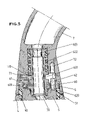
- FIG. 5 is a detail of the water mixing valve of FIG. 2 in enlarged view
- FIG. 6 is a top view of the control rings shown in FIG. 1 with their levers, the lever positions of the open-valve positions shown in dashed lines;
- FIG. 7 is the control rings with their levers for another water mixing valve in top schematic view, the open-valve positions of the adjustment levers being shown in dashed lines.
- the water mixing valve shown in FIGS. 1 to 6 of the drawing has a housing 1 , two valves 2 a and 2 b in the housing 1 , two control rings 3 and 4 , a headpiece 5 mounted on the housing 1 , a ring nut 6 held on the headpiece 5 , and a water spout 7 .
- the housing 1 has an end support face 13 by means of which it sits on an unillustrated wash and/or rinse surface. In order to secure the water mixing valve on the wash and/or rinse surface there is also a standard mounting device 14 on the housing 1 .
- the inlet fitting 8 a communicates with a cold-water inlet compartment 11 and the inlet fitting 8 b with a hot-water inlet compartment 12 .
- the cold-water compartment 11 opens into the valve 2 a while the hot-water compartment 12 opens into the valve 2 b .
- the two valves 2 a and 2 b extend parallel to a central axis 10 of the housing 1 and are of standard rotary construction with relatively rotatable ceramic disks or are standard valve bodies.
- the cold water coming out of the valve 2 a goes into a separate cold-water outlet compartment 110 and the hot water coming out of the valve 2 b goes into a separate hot-water outlet compartment 120 .
- the cold-water outlet compartment 110 and the hot-water outlet compartment 120 are connected via respective bores 111 and 121 with a mixed-water passage 70 in which the hot and cold water from the bores 111 and 121 mixes.
- the mixed-water passage 70 extends upward along the central axis 10 in the housing 1 as shown in FIG. 2 of the drawing.
- the two valves 2 a and 2 b are juxtaposed as closely as possible to the central axis 10 of the housing and are sealed by means of screwthreads and seal rings as is standard, the heads of the two valves 2 a and 2 b projecting out of the upper end of the housing 1 .
- the housing 1 has a frustoconical outer surface that is visible to the user.
- the headpiece 5 is secured by screws 52 ( FIG. 2 ) to the upper end of the housing 1 .
- the mixed-water passage 70 is sealed at its end with a seal 700 and has a region running at an angle to the axis 10 in the headpiece 5 .
- the headpiece 5 has cutouts for the portions of the valves 2 a and 2 b projecting from the housing 1 .
- respective gears 20 are mounted on the projecting stems of the valves 2 a and 2 b .
- Screws 21 in the stems of the valves 2 a and 2 b axially fix the gears 20 .
- the screws 21 each have an axially upwardly extending cylindrical pin 210 that engages in a respective tube 50 of the headpiece 5 .
- the gears 20 are each provided with an axially projecting sleeve 200 that surrounds the respective tubes 50 for further support.
- One of the gears 20 meshes with inside teeth of a gear 33 of the lower control ring 3 while the other gear 20 meshes with inside teeth of a gear 43 of the upper control ring 4 .
- the gear 43 is secured by splines to the control ring 4 and the gear 33 is similarly rotationally coupled by splines with the control ring 3 . Rotation of one or both of the control rings 3 and 4 about the central axis 10 thus is transmitted from the respective rings 3 and 4 to the valves 2 a and 2 b.
- Bushings 31 , 35 , and 41 of very low-friction and wear-resistant material support the control rings 3 and 4 .
- the bushing 31 bears on an upper end of the housing 1 while the upper bushing 41 bears radially on the headpiece 5 and axially on the ring nut 6 .
- the two bushings 31 and 41 each have a cylindrically stepped outer surface with the cylindrical surface forming a radial bearing surface while the step on the bushing 31 forms a shoulder and the step on the bushing 41 a shoulder that work as axial bearing surfaces.
- the middle bushing 35 between the control rings 3 and 4 is of rectangular section and provides for sliding support and axial positioning of the gears 33 and 43 in the rings 3 and 4 as shown in particular in FIG. 3 of the drawing.
- the outer surfaces of the control rings 3 and 4 are, like the housing, of frustoconical shape so that there is a smooth continuous transition from the outer surface of the housing 1 to that of the control rings 3 and 4 and the water spout 7
- the control ring 3 for the valve 2 a is provided with a radially outwardly extending lever 30 .
- the control ring 4 has a radially projecting lever 40 .
- the control lever 30 for the valve 2 a that controls cold-water flow is here somewhat longer than the control lever 40 that controls hot-water flow.
- the respective levers 30 and 40 extend in the same direction generally at a right angle to the front of the user. Each lever 30 and 40 can be moved separately from the closed position as shown by arrow 9 .
- a pipe nipple 60 is threaded into the upper end of the headpiece 5 and the mixed-water passage 70 opens into this nipple 60 .
- the outer surface of the pipe nipple 60 has above the end of the headpiece 5 a screwthread 61 carrying the ring nut 6 .
- the ring nut 6 itself has four symmetrically spaced threaded bores 600 in each of which a holding screw 62 can be screwed. Alternatively of course there could be six or eight symmetrically arrayed threaded bores. In addition two diametrally opposite holding screws could be provided in the ring nut for symmetrical loading of the ring nut.
- the ring nut 6 is torqued down on the screwthread 61 and then backed off until the next bore 600 is aligned with a conical seat 51 of the headpiece 5 . Then a holding screw 62 can engage with its conical tip 620 in the conical seat 51 , fixing the ring nut 6 in its angular position, and the axial play is set.
- the downstream end region of the pipe nipple 60 carries an external seal ring 602 that seals in a bore 603 of the water spout 7 .
- the illustrated holding screw 62 is not used and is replaced with a different holding screw with an axially projecting pin that when installed engages in a seat 72 of the spout 7 and thus fixes the spout 7 against rotation.
- mixing faucet is set up for mounting on a wash and/or rinse surface.
- mixing faucet according to the invention could also be used with appropriate connections as a wall-mount or other system.
- FIG. 7 of the drawing shows a different arrangement of the levers 30 and 40 for actuating different valves 2 a and 2 b .
- the levers 30 and 40 are 180° offset from one another. If the lever 30 is swung in the direction of an arrow 90 , the cold-water valve is uniformly opened. In the dashed-line position of the lever 30 the cold-water valve is fully open. If the lever 40 is swung in the direction of an arrow 91 , the hot-water valve is uniformly opened. In the dashed-line position of the lever 40 the hot-water valve is fully open.
Landscapes
- Engineering & Computer Science (AREA)
- General Engineering & Computer Science (AREA)
- Mechanical Engineering (AREA)
- Multiple-Way Valves (AREA)
- Domestic Plumbing Installations (AREA)
- Stabilization Of Oscillater, Synchronisation, Frequency Synthesizers (AREA)
- Confectionery (AREA)
- Mechanically-Actuated Valves (AREA)
Applications Claiming Priority (3)
| Application Number | Priority Date | Filing Date | Title |
|---|---|---|---|
| DE10239177.7 | 2002-08-21 | ||
| DE10239177A DE10239177A1 (de) | 2002-08-21 | 2002-08-21 | Mischbatterie |
| PCT/EP2003/008234 WO2004027299A1 (de) | 2002-08-21 | 2003-07-25 | Mischbatterie |
Publications (2)
| Publication Number | Publication Date |
|---|---|
| US20050115617A1 US20050115617A1 (en) | 2005-06-02 |
| US7171984B2 true US7171984B2 (en) | 2007-02-06 |
Family
ID=31197404
Family Applications (1)
| Application Number | Title | Priority Date | Filing Date |
|---|---|---|---|
| US10/491,584 Expired - Fee Related US7171984B2 (en) | 2002-08-21 | 2003-07-25 | Mixer tap |
Country Status (9)
| Country | Link |
|---|---|
| US (1) | US7171984B2 (de) |
| EP (1) | EP1436536B1 (de) |
| JP (1) | JP2005536702A (de) |
| AT (1) | ATE305103T1 (de) |
| AU (1) | AU2003251644A1 (de) |
| CA (1) | CA2465365A1 (de) |
| DE (2) | DE10239177A1 (de) |
| ES (1) | ES2248776T3 (de) |
| WO (1) | WO2004027299A1 (de) |
Cited By (6)
| Publication number | Priority date | Publication date | Assignee | Title |
|---|---|---|---|---|
| US20100180968A1 (en) * | 2007-09-27 | 2010-07-22 | Siegfried Heerklotz | Mixing Faucet |
| USD633599S1 (en) * | 2008-05-28 | 2011-03-01 | Caroma Industries Limited | Mixer tap |
| US20160146375A1 (en) * | 2012-06-22 | 2016-05-26 | Kohler Mira Limited | Valve with heating element |
| US10829916B2 (en) | 2017-04-26 | 2020-11-10 | Delta Faucet Company | User interface for a faucet |
| US10927967B2 (en) * | 2017-01-11 | 2021-02-23 | Kohler Co. | Faucet with multi-directional controls |
| US11391021B2 (en) | 2017-11-09 | 2022-07-19 | Kohler Mira Limited | Plumbing component |
Families Citing this family (8)
| Publication number | Priority date | Publication date | Assignee | Title |
|---|---|---|---|---|
| JP4638201B2 (ja) * | 2004-10-28 | 2011-02-23 | 株式会社ケーブイケー | 混合水栓 |
| GB0526333D0 (en) * | 2005-12-23 | 2006-02-01 | Horne Engineering Co Ltd | Water tap or faucet |
| US20100126614A1 (en) * | 2008-11-24 | 2010-05-27 | Tien-Ho Chung | Separated-control valve device |
| DE102015101651B4 (de) * | 2015-02-05 | 2018-07-12 | Aloys F. Dornbracht Gmbh & Co. Kg | Sanitärarmatur |
| CN107559457A (zh) * | 2017-10-12 | 2018-01-09 | 江门市立朗卫浴有限公司 | 一种抽拉式龙头 |
| DE102019114077A1 (de) * | 2019-05-27 | 2020-12-03 | Oras Oy | Befestigungsvorrichtung sowie Sanitärarmatur mit einer solchen Befestigungsvorrichtung |
| CN112497705B (zh) * | 2020-11-09 | 2023-05-09 | 绍兴文理学院 | 一种tpu薄膜的制备装置 |
| DE102022132924A1 (de) * | 2022-12-12 | 2024-06-13 | Grohe Ag | Sanitärarmatur |
Citations (7)
| Publication number | Priority date | Publication date | Assignee | Title |
|---|---|---|---|---|
| US2633872A (en) * | 1947-04-21 | 1953-04-07 | Vincent D Hennessey | Valve actuating mechanism and assemblage |
| US3067771A (en) * | 1958-05-19 | 1962-12-11 | Dole Valve Co | Pneumatic fluid control valve |
| US3511279A (en) * | 1968-04-17 | 1970-05-12 | Crosweller & Co Ltd W | Fluid mixing devices |
| US3584654A (en) * | 1967-05-19 | 1971-06-15 | Jean Louis Deloye | Sanitary mixing faucet |
| FR2565658A1 (fr) | 1984-06-07 | 1985-12-13 | Mbd Groupe Design | Dispositif melangeur pour robinetterie sanitaire |
| DE3820855A1 (de) | 1988-02-12 | 1989-08-24 | Sol Spa | Betaetigungsvorrichtung fuer mischbatterien fuer kaltes und warmes wasser |
| US5950663A (en) * | 1998-03-05 | 1999-09-14 | Bloomfield; Terence M. | Faucet installation system |
-
2002
- 2002-08-21 DE DE10239177A patent/DE10239177A1/de not_active Withdrawn
-
2003
- 2003-07-25 US US10/491,584 patent/US7171984B2/en not_active Expired - Fee Related
- 2003-07-25 JP JP2004536910A patent/JP2005536702A/ja active Pending
- 2003-07-25 CA CA 2465365 patent/CA2465365A1/en not_active Abandoned
- 2003-07-25 AT AT03797213T patent/ATE305103T1/de not_active IP Right Cessation
- 2003-07-25 WO PCT/EP2003/008234 patent/WO2004027299A1/de not_active Ceased
- 2003-07-25 AU AU2003251644A patent/AU2003251644A1/en not_active Abandoned
- 2003-07-25 EP EP03797213A patent/EP1436536B1/de not_active Expired - Lifetime
- 2003-07-25 DE DE50301223T patent/DE50301223D1/de not_active Expired - Lifetime
- 2003-07-25 ES ES03797213T patent/ES2248776T3/es not_active Expired - Lifetime
Patent Citations (7)
| Publication number | Priority date | Publication date | Assignee | Title |
|---|---|---|---|---|
| US2633872A (en) * | 1947-04-21 | 1953-04-07 | Vincent D Hennessey | Valve actuating mechanism and assemblage |
| US3067771A (en) * | 1958-05-19 | 1962-12-11 | Dole Valve Co | Pneumatic fluid control valve |
| US3584654A (en) * | 1967-05-19 | 1971-06-15 | Jean Louis Deloye | Sanitary mixing faucet |
| US3511279A (en) * | 1968-04-17 | 1970-05-12 | Crosweller & Co Ltd W | Fluid mixing devices |
| FR2565658A1 (fr) | 1984-06-07 | 1985-12-13 | Mbd Groupe Design | Dispositif melangeur pour robinetterie sanitaire |
| DE3820855A1 (de) | 1988-02-12 | 1989-08-24 | Sol Spa | Betaetigungsvorrichtung fuer mischbatterien fuer kaltes und warmes wasser |
| US5950663A (en) * | 1998-03-05 | 1999-09-14 | Bloomfield; Terence M. | Faucet installation system |
Cited By (25)
| Publication number | Priority date | Publication date | Assignee | Title |
|---|---|---|---|---|
| US20100180968A1 (en) * | 2007-09-27 | 2010-07-22 | Siegfried Heerklotz | Mixing Faucet |
| US8631823B2 (en) * | 2007-09-27 | 2014-01-21 | Siegfried Heerklotz | Mixing faucet |
| USD633599S1 (en) * | 2008-05-28 | 2011-03-01 | Caroma Industries Limited | Mixer tap |
| US10087607B2 (en) | 2012-06-22 | 2018-10-02 | Kohler Mira Limited | Shower head with integrated mixing valve |
| US10494798B2 (en) | 2012-06-22 | 2019-12-03 | Kohler Mira Limited | Plumbing fixture with heating element |
| US9689149B2 (en) | 2012-06-22 | 2017-06-27 | Kohler Mira Limited | Flow control valve |
| US9758950B2 (en) | 2012-06-22 | 2017-09-12 | Kohler Mira Limited | Plumbing fixture with integrated mixing valve |
| US9909288B2 (en) | 2012-06-22 | 2018-03-06 | Kohler Mira Limited | Plumbing fixture with mixing valve and controller |
| US9957699B2 (en) | 2012-06-22 | 2018-05-01 | Kohler Mira Limited | Plumbing fixture with heating elements |
| US9957700B2 (en) * | 2012-06-22 | 2018-05-01 | Kohler Mira Limited | Valve with heating element |
| US10000914B2 (en) | 2012-06-22 | 2018-06-19 | Kohler Mira Limited | Plumbing fixture with user interface |
| US10041234B2 (en) | 2012-06-22 | 2018-08-07 | Kohler Mira Limited | Mixing valve |
| US20160146375A1 (en) * | 2012-06-22 | 2016-05-26 | Kohler Mira Limited | Valve with heating element |
| US10106964B2 (en) | 2012-06-22 | 2018-10-23 | Kohler Mira Limited | Method of controlling mixing valve |
| US9683352B2 (en) | 2012-06-22 | 2017-06-20 | Kohler Mira Limited | Valve disinfecting method |
| US10501915B2 (en) | 2012-06-22 | 2019-12-10 | Kohler Mira Limited | Plumbing fixture with user interface |
| US10577784B2 (en) | 2012-06-22 | 2020-03-03 | Kohler Mira Limited | Shower head with integrated mixing valve |
| US10604919B2 (en) | 2012-06-22 | 2020-03-31 | Kohler Mira Limited | Plumbing fixture with heating element |
| US11674293B2 (en) | 2012-06-22 | 2023-06-13 | Kohler Mira Limited | Mixing valve |
| US11230829B2 (en) | 2012-06-22 | 2022-01-25 | Kohler Mira Limited | Mixing valve |
| US10927967B2 (en) * | 2017-01-11 | 2021-02-23 | Kohler Co. | Faucet with multi-directional controls |
| US12038092B2 (en) | 2017-01-11 | 2024-07-16 | Kohler Co. | Faucet with multi-directional controls |
| US10829916B2 (en) | 2017-04-26 | 2020-11-10 | Delta Faucet Company | User interface for a faucet |
| US11391021B2 (en) | 2017-11-09 | 2022-07-19 | Kohler Mira Limited | Plumbing component |
| US12392119B2 (en) | 2017-11-09 | 2025-08-19 | Kohler Mira Limited | Plumbing component |
Also Published As
| Publication number | Publication date |
|---|---|
| AU2003251644A1 (en) | 2004-04-08 |
| US20050115617A1 (en) | 2005-06-02 |
| DE50301223D1 (de) | 2006-02-02 |
| WO2004027299A1 (de) | 2004-04-01 |
| ATE305103T1 (de) | 2005-10-15 |
| EP1436536A1 (de) | 2004-07-14 |
| JP2005536702A (ja) | 2005-12-02 |
| ES2248776T3 (es) | 2006-03-16 |
| DE10239177A1 (de) | 2004-03-04 |
| CA2465365A1 (en) | 2004-04-01 |
| EP1436536B1 (de) | 2005-09-21 |
Similar Documents
| Publication | Publication Date | Title |
|---|---|---|
| US7171984B2 (en) | Mixer tap | |
| CN102272500B (zh) | 在具有锁定机构的单操作杆热/冷水龙头上使用的仅在热水侧的弹簧复位 | |
| US8061386B2 (en) | Swivel joint for faucet | |
| US4981156A (en) | Temperature and volume control valve assembly | |
| US4901750A (en) | Temperature and volume control valve assembly | |
| US6880565B2 (en) | Shower bath tap valve assembly | |
| US20070044850A1 (en) | Fluid control apparatus for a faucet | |
| US5657791A (en) | Control cartridge for a single-lever mixer fitting | |
| US20080245897A1 (en) | Showerhead | |
| US20130334324A1 (en) | Thermostatic mixing valve with integrated flow diverter | |
| US20050076960A1 (en) | Mixing faucet | |
| US4346735A (en) | Water faucet and attachment therefor | |
| SE510313C2 (sv) | Handtagsanordning för tappkranar | |
| US2966928A (en) | Fluid mixing devices | |
| US2609206A (en) | Mixing faucet | |
| US7509976B2 (en) | Multi-port diverter valve | |
| US3168112A (en) | Temperature mixing and diverting valve for domestic plumbing fixtures | |
| AU2003303349A1 (en) | Sanitary outflow fitting | |
| US3155115A (en) | Cam operated tilting valves | |
| EP1703026A2 (de) | Fluidverteileinrichtung | |
| US20070028975A1 (en) | Mixer valve | |
| US8739827B2 (en) | Single-lever mixing gear for a plumbing fixture | |
| US4050475A (en) | Mixing faucet | |
| DK2634317T3 (en) | SANITARY FITTINGS | |
| US6655410B2 (en) | Multi-way hydraulic distributor with an interception unit |
Legal Events
| Date | Code | Title | Description |
|---|---|---|---|
| AS | Assignment |
Owner name: FRIEDRICH GROHE AG & CO. KG, GERMANY Free format text: ASSIGNMENT OF ASSIGNORS INTEREST;ASSIGNORS:PAWELZIK, MANFRED;HANNEMANN, FRED;REEL/FRAME:016322/0922;SIGNING DATES FROM 20040305 TO 20040317 |
|
| AS | Assignment |
Owner name: GROHE WATER TECHNOLOGY AG & CO. KG, GERMANY Free format text: CHANGE OF NAME;ASSIGNOR:FRIEDRICH GROHE AG & CO. KG;REEL/FRAME:016839/0760 Effective date: 20031105 |
|
| REMI | Maintenance fee reminder mailed | ||
| LAPS | Lapse for failure to pay maintenance fees | ||
| STCH | Information on status: patent discontinuation |
Free format text: PATENT EXPIRED DUE TO NONPAYMENT OF MAINTENANCE FEES UNDER 37 CFR 1.362 |
|
| FP | Lapsed due to failure to pay maintenance fee |
Effective date: 20110206 |