US7217019B2 - Vehicle light having a cruciform light distribution - Google Patents
Vehicle light having a cruciform light distribution Download PDFInfo
- Publication number
- US7217019B2 US7217019B2 US10/506,077 US50607704A US7217019B2 US 7217019 B2 US7217019 B2 US 7217019B2 US 50607704 A US50607704 A US 50607704A US 7217019 B2 US7217019 B2 US 7217019B2
- Authority
- US
- United States
- Prior art keywords
- crossbars
- vehicle lamp
- set forth
- light
- optical system
- Prior art date
- Legal status (The legal status is an assumption and is not a legal conclusion. Google has not performed a legal analysis and makes no representation as to the accuracy of the status listed.)
- Expired - Lifetime
Links
Images




Classifications
-
- B—PERFORMING OPERATIONS; TRANSPORTING
- B60—VEHICLES IN GENERAL
- B60Q—ARRANGEMENT OF SIGNALLING OR LIGHTING DEVICES, THE MOUNTING OR SUPPORTING THEREOF OR CIRCUITS THEREFOR, FOR VEHICLES IN GENERAL
- B60Q1/00—Arrangement of optical signalling or lighting devices, the mounting or supporting thereof or circuits therefor
- B60Q1/26—Arrangement of optical signalling or lighting devices, the mounting or supporting thereof or circuits therefor the devices being primarily intended to indicate the vehicle, or parts thereof, or to give signals, to other traffic
- B60Q1/32—Arrangement of optical signalling or lighting devices, the mounting or supporting thereof or circuits therefor the devices being primarily intended to indicate the vehicle, or parts thereof, or to give signals, to other traffic for indicating vehicle sides, e.g. clearance lights
Definitions
- the invention concerns a vehicle lamp, in particular a side marking lamp, as set forth in the classifying portion of claim 1 .
- the minimum requirements in terms of the visibility range are prescribed for example at 10° upwardly and downwardly respectively and 45° towards the left and the right respectively from a reference axis HV (center line extending in the direction of radiation) of the lamp. In that respect a uniform minimum light intensity is required in the entire visibility range. It is only at the center of light distribution that the light intensity must be markedly higher.
- FIG. 1 shows the minimum photometric requirements for a side marking lamp.
- the window illustrated represents the minimum visibility range of the side marking lamp, with a radiation angle, in relation to a center point 5 , of 10° upwardly and downwardly, as indicated at 10° U and 10° D, and 45° towards the left and the right, as indicated at 45° L, 45° R.
- a substantially higher level of light intensity of for example 4 cd is prescribed at the center point 5 (central peak) than in the region 4 (for example 0.6 cd).
- Known lamps which can be mounted in different positions include an optical system which for example produces a circular projection, as is illustrated in FIG. 2 by reference numeral 1 .
- an optical system which for example produces a circular projection, as is illustrated in FIG. 2 by reference numeral 1 .
- the object of the present invention is to provide a vehicle lamp which can be mounted in positions which are turned relative to each other through 90° in each case and which is as inexpensive as possible and which nonetheless satisfies the minimum photometric requirements.
- the essential concept of the invention is that of providing a vehicle lamp, in particular a side marking lamp, with an optical system which produces a cruciform light distribution.
- a substantially smaller projection area namely only a cruciform projection area
- substantially less light power is required for that purpose. It is thus possible to use weaker and therefore more favourable light sources, the light emitted from which is used substantially more efficiently than in the state of the art.
- the lamp in addition it is possible for the lamp to be mounted in a plurality of positions, preferably in four positions, turned in each case through 90°.
- a side marking lamp it can be fitted for example both horizontally and also vertically (turned through 90°) to a vertical side wall of a vehicle.
- the lamp includes 2n LEDs, wherein n is an integer ⁇ 1.
- a possible way of implementing the cruciform light distribution involves the use of an optical system of cruciform configuration.
- the optical system according to the invention preferably has a central converging lens. As a result the level of light intensity at the center of the light distribution can be additionally increased.
- the optical system is preferably arranged in or on a light exit surface, for example a surface formed from transparent plastic material.
- a particularly preferred vehicle lamp includes two cruciform optical systems, each of which deflects the light incident thereon from the light source into the one bar of the cross of the cruciform light distribution produced thereby more strongly than into the other bar of the cross configuration.
- those two optical systems are positioned in mutually juxtaposed relationship in such a way that the two ‘light beams’ delivered thereby and each being of a cruciform cross-section, after passing through a very small near region, combine in such a way that, at medium and great distance, they produce a single cruciform light spot on a projection surface which is perpendicular to HV.
- the two optical systems are arranged turned through 90° relative to each other, the above-described asymmetry of the light distribution on to the two crossbars of the individual ‘light beams’ is completely compensated in the combined overall light beam and the vehicle lamp can be turned in 90° steps without anything being changed in terms of the distribution of intensity of the overall light beam produced, in the medium or far region.
- FIG. 1 is a view of a light distribution for a side marking lamp in accordance with minimum photometric requirements
- FIG. 2 is a view of a light distribution when using an optical system according to the invention
- FIG. 3 is a plan view of the rear side, which is towards the light source, of an optical system according to the invention for producing an asymmetrical, cruciform light distribution,
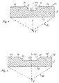
- FIG. 4 shows a view in section through the optical system of FIG. 3 taken along line IV—IV,
- FIG. 5 shows a view in section through the optical system of FIG. 3 taken along line V—V
- FIG. 6 shows a view in section through the optical system of FIG. 3 taken along line VI—VI,
- FIG. 7 shows a view in section through the optical system of FIG. 3 taken along line VII—VII,
- FIG. 8 is a plan view similar to FIG. 3 on to the rear side, which is towards two light sources, of two mutually juxtaposed optical systems which jointly produce a symmetrical, cruciform light distribution, and
- FIG. 9 shows a perspective view of a light cover of a vehicle lamp with an integrated optical system as shown in FIG. 8 .
- FIG. 2 shows the circular projection 1 of a light cone as is emitted by conventional vehicle lamps which can be mounted to a vehicle wall both vertically and also horizontally (that is to say turned through 90°). Because of the relatively large irradiated area the light power required in respect of the light source used is also relatively high.
- a lamp in accordance with the invention therefore includes an optical system which produces a cruciform light distribution 3 with two mutually perpendicular light bars 3 a and 3 b .
- a lamp according to the invention can also be installed in a position of being turned through 90° without the light distribution of the light cone which is projected into space being markedly altered.
- the area of the light bars 3 a , 3 b at any distance from the light source, is substantially smaller than that of the associated circular cone cross-section 1 , a substantially lower level of light power is sufficient to achieve the same, prescribed brightness.
- the light bar 3 a with respect to the central light cone axis HV, involves an extent of 10° upwardly and downwardly respectively and 45° towards the left and the right respectively.
- the vertical light bar 3 b is of a vertical extent of 10° towards the left and the right and a vertical extent of 45° upwardly and downwardly respectively so that, when the lamp according to the invention is turned through 90°, the light bar 3 b can readily perform the function of the horizontal light bar.
- FIG. 3 shows an optical system 6 a for a lamp according to the invention which, in combination with an identical optical system 6 b (see FIG. 8 ) which is arranged beside it and turned through 90°, is in a position to produce the horizontally and vertically completely symmetrical light distribution which is shown in FIG. 2 .
- Each of the optical systems 6 ′ and 6 ′′ is formed in a plate-shaped body 8 ′, 8 ′′ of a transparent material and is of a substantially square shape in the plan view shown in FIGS. 3 and 8 respectively.
- a light source 7 ′, 7 ′′ preferably a light emitting diode, which radiates a conical light beam 13 on to the rear side 10 of the body 8 ′′, 8 ′′, which is opposite to the viewer, in such a way that the central axis of symmetry HV of that light beam 13 impinges on that rear side 10 in substantially perpendicular relationship and passes through the body 8 ′, 8 ′′ at the centre of the square formed by the respective optical system 6 ′ and 6 ′′, respectively without a change in direction.
- the body 8 ′ is substantially in the form of a flat plate with plane-parallel front and rear sides 9 and 10 respectively, in which respect however incorporated into the rear sides 10 is a row of optically active structures which are described in greater detail hereinafter.
- optically active structure is used to denote any lens-like or prism-like structure which is capable of changing the direction of light beams passing therethrough, through a predetermined angle.
- each of the optical systems 6 ′, 6 ′′ has a plurality of optically inactive regions 12 , through which the incident light passes without a change in direction.
- the various regions 12 do not necessarily have to be of the same thickness.
- the only aspect which is common to them is optical inactivity in the above-defined sense.
- FIGS. 3 and 8 show the optically active structures of each optical system 6 ′ and 6 ′′ respectively are arranged along two crossbars 14 ′, 14 ′′, 16 ′′, 16 ′′, the central axes 18 ′, 20 ′, 18 ′′, 20 ′′ of which cross at the center of the respective square, that is to say at the point of intersection 15 ′ being concentric with the central axis HV of the incident light cone 13 .
- each crossbar 14 ′, 14 ′′ and 16 ′, 16 ′′ are of a symmetrical configuration with respect to the center just referred to above, but the two crossbars 14 ′, 14 ′′, 16 ′, 16 ′′ differ from each other in terms of the optically active individual structures forming them.
- a converging lens 22 ′, 22 ′′ which focuses the light impinging thereon in such a way that it produces the required brightness peak in the HV direction.
- the optically active individual elements adjoining the central converging lens 22 ′, 22 ′′ in the crossbars 14 ′, 14 ′′, 16 ′, 16 ′′ provide for re-distribution of the incident light from regions with a light excess at the center of the arrangement and the area immediately surrounding same into the further outwardly disposed angular regions which involve a light deficiency.
- the central lens 22 ′ is of only a relatively small extent in the direction of the crossbar 14 ′ so that in the plan view in FIG. 3 it appears as a circle which is cut off on two sides, wherein the two secants 23 , 24 extend in parallel relationship with the central axis 20 ′ of the horizontal crossbar 16 ′.
- an optically active structure 26 which is shown in the sectional view in FIG.
- a respective optically inactive region 12 then outwardly adjoins the optically active regions 27 .
- the central lens 22 ′ is of a substantially greater extent in the direction of the central axis 22 ′ of the crossbar 16 ′ so that here the full circular shape is attained.
- two optically active elements 28 , 29 which are both shown in the sectional view in FIG. 5 in the form of rising prismatic edge surfaces, wherein the edge surface of the optically active element 28 is steeper than that of the optically active element 29 .
- the two distribute only outwardly the light incident thereon, similarly to the optically active elements 26 .
- Adjoining the optically active elements 29 on both sides is an optically active element 30 , the significance of which is explained hereinafter.
- the horizontal crossbar 16 ′ includes optically active elements 31 which, as can be seen from FIG. 6 , are in the form of segments of a cylinder, wherein the longitudinal axes of those cylinders extend in parallel relationship with the central axis 2 O′ of the horizontal crossbar 16 ′.
- optically active elements 31 light from regions outside the required zones is refracted in such a way that it is incident in the regions in which an increase in the intensity of light is required.
- the vertical crossbar 14 ′ also includes optically active regions 32 (see FIG. 7 ) which are in the form of segments of a cylinder and which perform the same function as the optically active elements 31 .
- the crossbars 14 ′, 16 ′ and 14 ′′, 16 ′′ are not of an identical configuration, as already indicated above.
- the optically active elements 26 and 27 which are disposed between the optically active elements 32 of the vertical crossbar 14 ′, extending in the longitudinal direction of the bar, like the optically inactive regions 12 thereof, are of the correct width to allow the light to pass therethrough in the required angular region and distribute it in the vertical crossbar 14 ′ respectively.
- the remaining space, for the horizontal crossbar 16 ′, is not sufficient for it to be of the same width so that its optically active regions 28 , 29 , 30 must be narrower, in perpendicular relationship with the central axis 20 ′.
- the concave, optically active region 30 which has already been mentioned hereinbefore with reference to FIG. 5 and which, as shown in FIG. 7 , is not present in the vertical crossbar 14 ′.
- the two optical systems 6 ′ and 6 ′′ are of an identical configuration, as was described with reference to FIGS. 3 through 7 .
- the bodies 8 ′, 8 ′′ which comprise a transparent material and into the rear side of which is incorporated the respective optical system 6 ′ and 6 ′′ respectively are preferably integrally connected to each other and form for example a part of the light transmission cover 10 of the vehicle lamp shown in FIG. 9 .
- the arrangement of the two optical systems 6 ′ and 6 ′′ in a common plane and the above-described configuration of the optically active elements thereof can provide that the light passing through them, after passing through a near range which is only a few centimeters, is combined to form a single overall light beam which, at medium and greater distances, is of a cruciform cross-section, the two crossbars involving identical light distribution effects.
- FIG. 9 is another perspective view of a vehicle lamp according to the invention, wherein two fixing openings 40 are illustrated in addition to the above-described elements.
Landscapes
- Engineering & Computer Science (AREA)
- Mechanical Engineering (AREA)
- Non-Portable Lighting Devices Or Systems Thereof (AREA)
- Lighting Device Outwards From Vehicle And Optical Signal (AREA)
Applications Claiming Priority (4)
| Application Number | Priority Date | Filing Date | Title |
|---|---|---|---|
| DE20214039.3 | 2002-09-11 | ||
| DE20214039 | 2002-09-11 | ||
| DE20214039U DE20214039U1 (de) | 2002-09-11 | 2002-09-11 | Fahrzeugleuchte mit kreuzförmiger Lichtverteilung |
| PCT/EP2003/010127 WO2004026627A1 (de) | 2002-09-11 | 2003-09-11 | Fahrzeugleuchte mit kreuzförmiger lichtverteilung |
Publications (2)
| Publication Number | Publication Date |
|---|---|
| US20050117360A1 US20050117360A1 (en) | 2005-06-02 |
| US7217019B2 true US7217019B2 (en) | 2007-05-15 |
Family
ID=7974979
Family Applications (1)
| Application Number | Title | Priority Date | Filing Date |
|---|---|---|---|
| US10/506,077 Expired - Lifetime US7217019B2 (en) | 2002-09-11 | 2003-09-11 | Vehicle light having a cruciform light distribution |
Country Status (11)
| Country | Link |
|---|---|
| US (1) | US7217019B2 (de) |
| EP (1) | EP1463651B1 (de) |
| JP (1) | JP2006511037A (de) |
| CN (1) | CN1681686A (de) |
| AT (1) | ATE319590T1 (de) |
| AU (1) | AU2003267345A1 (de) |
| CA (1) | CA2498806A1 (de) |
| DE (2) | DE20214039U1 (de) |
| ES (1) | ES2260641T3 (de) |
| PL (1) | PL374204A1 (de) |
| WO (1) | WO2004026627A1 (de) |
Families Citing this family (1)
| Publication number | Priority date | Publication date | Assignee | Title |
|---|---|---|---|---|
| AU2017269239A1 (en) * | 2016-05-21 | 2019-01-03 | JST Performance, LLC | Method and apparatus for vehicular light fixtures |
Citations (14)
| Publication number | Priority date | Publication date | Assignee | Title |
|---|---|---|---|---|
| US1284016A (en) * | 1918-03-07 | 1918-11-05 | Llewellyn Wise | Lamp. |
| US1371470A (en) * | 1921-03-15 | Radiant annunciator-sign | ||
| US3703636A (en) * | 1971-04-07 | 1972-11-21 | Roman A Schmitt | Anti-fog headlight with opaque mask |
| US4240220A (en) * | 1979-04-26 | 1980-12-23 | Barry Smith | Reflector with illuminated indicia |
| EP0404990A1 (de) | 1989-06-30 | 1991-01-02 | Hella KG Hueck & Co. | Kraftfahrzeugleuchte |
| US5226723A (en) | 1992-05-11 | 1993-07-13 | Chen Der Jong | Light emitting diode display |
| US5444932A (en) * | 1991-03-07 | 1995-08-29 | Werbelicht Kg Rudolf Jeroma | Electric sign advertising element |
| US5564816A (en) * | 1995-04-21 | 1996-10-15 | Arcadia; Alexander J. | Illuminated memorial assembly |
| DE19728354A1 (de) | 1997-07-03 | 1999-01-07 | Sidler Gmbh & Co | Vorsatz für eine Leuchtdiode und Bremsleuchte für ein Kraftfahrzeug |
| DE19830298A1 (de) | 1998-07-07 | 2000-02-17 | Bosch Gmbh Robert | Scheinwerferanordnung für Kraftfahrzeuge |
| DE19951407A1 (de) | 1999-10-26 | 2001-05-03 | Hella Kg Hueck & Co | Kraftfahrzeugleuchte |
| DE10036323A1 (de) | 2000-07-26 | 2002-02-07 | Hella Kg Hueck & Co | Leuchte für Fahrzeuge |
| DE20211305U1 (de) | 2002-07-26 | 2002-10-10 | Automotive Lighting Reutlingen | Beleuchtungseinrichtung für ein Kraftfahrzeug mit mehreren Leuchteinheiten |
| US6837602B1 (en) * | 2003-09-23 | 2005-01-04 | Fu An Industrial Co., Ltd. | Cover for a shell of a tail-light of a vehicle |
-
2002
- 2002-09-11 DE DE20214039U patent/DE20214039U1/de not_active Expired - Lifetime
-
2003
- 2003-09-11 US US10/506,077 patent/US7217019B2/en not_active Expired - Lifetime
- 2003-09-11 PL PL03374204A patent/PL374204A1/xx not_active Application Discontinuation
- 2003-09-11 CN CNA038216728A patent/CN1681686A/zh active Pending
- 2003-09-11 ES ES03748009T patent/ES2260641T3/es not_active Expired - Lifetime
- 2003-09-11 AT AT03748009T patent/ATE319590T1/de not_active IP Right Cessation
- 2003-09-11 JP JP2004537056A patent/JP2006511037A/ja not_active Withdrawn
- 2003-09-11 WO PCT/EP2003/010127 patent/WO2004026627A1/de not_active Ceased
- 2003-09-11 DE DE50302611T patent/DE50302611D1/de not_active Expired - Lifetime
- 2003-09-11 EP EP03748009A patent/EP1463651B1/de not_active Expired - Lifetime
- 2003-09-11 CA CA002498806A patent/CA2498806A1/en not_active Abandoned
- 2003-09-11 AU AU2003267345A patent/AU2003267345A1/en not_active Abandoned
Patent Citations (14)
| Publication number | Priority date | Publication date | Assignee | Title |
|---|---|---|---|---|
| US1371470A (en) * | 1921-03-15 | Radiant annunciator-sign | ||
| US1284016A (en) * | 1918-03-07 | 1918-11-05 | Llewellyn Wise | Lamp. |
| US3703636A (en) * | 1971-04-07 | 1972-11-21 | Roman A Schmitt | Anti-fog headlight with opaque mask |
| US4240220A (en) * | 1979-04-26 | 1980-12-23 | Barry Smith | Reflector with illuminated indicia |
| EP0404990A1 (de) | 1989-06-30 | 1991-01-02 | Hella KG Hueck & Co. | Kraftfahrzeugleuchte |
| US5444932A (en) * | 1991-03-07 | 1995-08-29 | Werbelicht Kg Rudolf Jeroma | Electric sign advertising element |
| US5226723A (en) | 1992-05-11 | 1993-07-13 | Chen Der Jong | Light emitting diode display |
| US5564816A (en) * | 1995-04-21 | 1996-10-15 | Arcadia; Alexander J. | Illuminated memorial assembly |
| DE19728354A1 (de) | 1997-07-03 | 1999-01-07 | Sidler Gmbh & Co | Vorsatz für eine Leuchtdiode und Bremsleuchte für ein Kraftfahrzeug |
| DE19830298A1 (de) | 1998-07-07 | 2000-02-17 | Bosch Gmbh Robert | Scheinwerferanordnung für Kraftfahrzeuge |
| DE19951407A1 (de) | 1999-10-26 | 2001-05-03 | Hella Kg Hueck & Co | Kraftfahrzeugleuchte |
| DE10036323A1 (de) | 2000-07-26 | 2002-02-07 | Hella Kg Hueck & Co | Leuchte für Fahrzeuge |
| DE20211305U1 (de) | 2002-07-26 | 2002-10-10 | Automotive Lighting Reutlingen | Beleuchtungseinrichtung für ein Kraftfahrzeug mit mehreren Leuchteinheiten |
| US6837602B1 (en) * | 2003-09-23 | 2005-01-04 | Fu An Industrial Co., Ltd. | Cover for a shell of a tail-light of a vehicle |
Also Published As
| Publication number | Publication date |
|---|---|
| DE20214039U1 (de) | 2003-01-16 |
| PL374204A1 (en) | 2005-10-03 |
| AU2003267345A1 (en) | 2004-04-08 |
| ATE319590T1 (de) | 2006-03-15 |
| CA2498806A1 (en) | 2004-04-01 |
| DE50302611D1 (de) | 2006-05-04 |
| JP2006511037A (ja) | 2006-03-30 |
| WO2004026627A1 (de) | 2004-04-01 |
| CN1681686A (zh) | 2005-10-12 |
| US20050117360A1 (en) | 2005-06-02 |
| ES2260641T3 (es) | 2006-11-01 |
| EP1463651B1 (de) | 2006-03-08 |
| EP1463651A1 (de) | 2004-10-06 |
Similar Documents
| Publication | Publication Date | Title |
|---|---|---|
| US7553054B2 (en) | Vehicular lamp unit | |
| US5174649A (en) | Led lamp including refractive lens element | |
| US6811287B2 (en) | Single light-emitting diode vehicle lamp | |
| US10677410B2 (en) | Light beam adjusting device, vehicle lamp and motor vehicle | |
| US5388035A (en) | Automotive marker lamp | |
| US7055996B2 (en) | Side turn/marker lamp | |
| US8511848B2 (en) | Luminaire | |
| US6623150B2 (en) | Light-emitting diode combination marker/clearance lamp for trucks and trailers | |
| EP2187111B1 (de) | LED-Signalleuchte | |
| US8905608B2 (en) | Optical body for a vehicle light | |
| US11725801B2 (en) | Optical lens | |
| MX2010005408A (es) | Arreglos de luz de alerta, componentes y metodos. | |
| CN110469817B (zh) | 用于车灯的光学组件、车灯和机动车辆 | |
| US7217019B2 (en) | Vehicle light having a cruciform light distribution | |
| US11835201B2 (en) | Optical lens | |
| US6848801B2 (en) | Lighting panel for a display assembly | |
| KR100378993B1 (ko) | Led 교통신호등 | |
| TWI852758B (zh) | 用於照明行人穿越道的照明裝置 | |
| CN223953923U (zh) | 光学模组和照明系统 | |
| JP2006511037A5 (de) | ||
| CN224162463U (zh) | 一种组合工作灯 | |
| JP2006293645A (ja) | 信号機 | |
| KR102389797B1 (ko) | 휘도와 조도가 개선된 구조의 렌즈와 반사구조를 갖는 엘이디 조명장치 | |
| JP3082587U (ja) | Ledシグナルライト | |
| TWM651503U (zh) | 設置於行人穿越道的照明裝置 |
Legal Events
| Date | Code | Title | Description |
|---|---|---|---|
| AS | Assignment |
Owner name: FER FAHRZEUGELEKTRIK GMBH, GERMANY Free format text: ASSIGNMENT OF ASSIGNORS INTEREST;ASSIGNORS:WIMBERT, FRANK;WERNER, HERMANN;WOLFF, REINGARD;REEL/FRAME:016192/0563;SIGNING DATES FROM 20040803 TO 20040809 |
|
| STCF | Information on status: patent grant |
Free format text: PATENTED CASE |
|
| FEPP | Fee payment procedure |
Free format text: PAYOR NUMBER ASSIGNED (ORIGINAL EVENT CODE: ASPN); ENTITY STATUS OF PATENT OWNER: LARGE ENTITY |
|
| AS | Assignment |
Owner name: TRUCK-LITE EUROPE GMBH, GERMANY Free format text: CHANGE OF NAME;ASSIGNOR:FER FAHRZEUGELEKTRIK GMBH;REEL/FRAME:025204/0502 Effective date: 19900821 |
|
| FPAY | Fee payment |
Year of fee payment: 4 |
|
| FPAY | Fee payment |
Year of fee payment: 8 |
|
| AS | Assignment |
Owner name: REBO LIGHTING & ELECTRONICS GMBH, GERMANY Free format text: CHANGE OF NAME;ASSIGNOR:TRUCK-LITE EUROPE GMBH;REEL/FRAME:047378/0565 Effective date: 20171103 |
|
| MAFP | Maintenance fee payment |
Free format text: PAYMENT OF MAINTENANCE FEE, 12TH YEAR, LARGE ENTITY (ORIGINAL EVENT CODE: M1553); ENTITY STATUS OF PATENT OWNER: LARGE ENTITY Year of fee payment: 12 |