US7256565B2 - Wiper system using two wipers - Google Patents
Wiper system using two wipers Download PDFInfo
- Publication number
- US7256565B2 US7256565B2 US10/296,008 US29600803A US7256565B2 US 7256565 B2 US7256565 B2 US 7256565B2 US 29600803 A US29600803 A US 29600803A US 7256565 B2 US7256565 B2 US 7256565B2
- Authority
- US
- United States
- Prior art keywords
- wiper
- motors
- control unit
- wiper motors
- recited
- Prior art date
- Legal status (The legal status is an assumption and is not a legal conclusion. Google has not performed a legal analysis and makes no representation as to the accuracy of the status listed.)
- Expired - Fee Related
Links
- 230000001953 sensory effect Effects 0.000 claims abstract description 22
- 230000001105 regulatory effect Effects 0.000 claims abstract description 7
- 230000033001 locomotion Effects 0.000 description 5
- 238000004891 communication Methods 0.000 description 2
- 238000004140 cleaning Methods 0.000 description 1
- 230000001419 dependent effect Effects 0.000 description 1
- 238000001514 detection method Methods 0.000 description 1
- 238000000034 method Methods 0.000 description 1
- 230000002441 reversible effect Effects 0.000 description 1
- 230000003068 static effect Effects 0.000 description 1
- 230000001360 synchronised effect Effects 0.000 description 1
- 230000001960 triggered effect Effects 0.000 description 1
Images


Classifications
-
- B—PERFORMING OPERATIONS; TRANSPORTING
- B60—VEHICLES IN GENERAL
- B60S—SERVICING, CLEANING, REPAIRING, SUPPORTING, LIFTING, OR MANOEUVRING OF VEHICLES, NOT OTHERWISE PROVIDED FOR
- B60S1/00—Cleaning of vehicles
- B60S1/02—Cleaning windscreens, windows or optical devices
- B60S1/04—Wipers or the like, e.g. scrapers
- B60S1/06—Wipers or the like, e.g. scrapers characterised by the drive
- B60S1/08—Wipers or the like, e.g. scrapers characterised by the drive electrically driven
- B60S1/0814—Wipers or the like, e.g. scrapers characterised by the drive electrically driven using several drive motors; motor synchronisation circuits
-
- Y—GENERAL TAGGING OF NEW TECHNOLOGICAL DEVELOPMENTS; GENERAL TAGGING OF CROSS-SECTIONAL TECHNOLOGIES SPANNING OVER SEVERAL SECTIONS OF THE IPC; TECHNICAL SUBJECTS COVERED BY FORMER USPC CROSS-REFERENCE ART COLLECTIONS [XRACs] AND DIGESTS
- Y10—TECHNICAL SUBJECTS COVERED BY FORMER USPC
- Y10S—TECHNICAL SUBJECTS COVERED BY FORMER USPC CROSS-REFERENCE ART COLLECTIONS [XRACs] AND DIGESTS
- Y10S318/00—Electricity: motive power systems
- Y10S318/02—Windshield wiper controls
Definitions
- the present invention relates to a wiper system using two wipers.
- wipe areas Different types of wipe areas and driving devices are known for cleaning windshields of motor vehicles. With respect to wipe areas, distinctions are mainly made between single-arm wipe areas and dual-arm wipe areas. In dual-arm wipe areas, the wiper arms of the wipers may be operated in tandem or in opposition.
- the drive device generally uses only one wiper motor whose rotary drive movement of its driven shaft is translated into an oscillating swivel motion of the drive shafts of the wipers via a spatial crank drive.
- Newer wiper motors are provided with electronics which regulate a reversing drive movement of the driven shaft.
- the electronics also allow a control of the wipe angle including a dynamic, load-dependent wipe-angle correction and wiping-speed regulation, thereby producing a larger nominal wiped area on the windshield.
- the electronic system allows different wipe functions and positions, such as an extended parking position, a service position for changing a wiper blade, an interval parking position and an alternating parking position for relieving the load on the wiper blades.
- the wiper motors having an electronic system are provided with a control device including sensors for regulating the position and speed of the driven shaft and a micro-controller for detecting the position of the driven shaft. This leads to higher expenditures for the control device and requires additional space in the hood.
- Wiper systems using opposed wipers are often used for wiping larger windshields. If these systems are driven by a wiper motor, a large size in accordance with the vehicle width results and a large space in the center of the vehicle. Also, the kinematic design with or without intermediate bearing is complicated and necessitates a large, high-capacity wiper motor. The many individual mechanical components produce large static wipe-angle tolerances in addition to dynamic wipe-angle tolerances which are caused by elasticities of the mechanical components and of the components of the support and fastening elements.
- wiper systems using two wiper motors are utilized, which are located in the area of the wiper bearings and, therefore, do not require space in the center region of the windshield.
- Two synchronously running wiper motors having electronic communication are used for the driving.
- each wiper motor is provided with a full electronic system. Wiper motors are preferably regulated in reversing operating so as to obtain the advantages associated therewith.
- the second wiper motor is designed as a rotary motor and has only one sensory system for detecting the absolute and relative rotational position of its driven shaft.
- the sensory system generates corresponding signals for the control unit of the first wiper motor to which it is connected via a communication interface. From these signals, the control unit advantageously forms a setpoint value for regulating the rotational position and rotational speed of the first wiper motor, so that it is regulated as a function of the rotational position and the rotational speed of the driven shaft of the second wiper motor.
- the first wiper motor which works as a so-called “master”, is expediently, but not necessarily, positioned on the driver side of the vehicle and is preferably operated in reversible operation. Accordingly, the second wiper motor, also known as a “slave”, is mounted on the passenger side.
- the second wiper motor requires less space since it has no separate electronic control unit, especially no micro-controller. Nevertheless, the complete function of the reversing motor is available on the driver side, such as a wipe-angle correction, extended parking position etc. Lastly, a security concept is possible by which the collision of the wipers is avoided, among others.
- the first wiper motor has an interface, or direct wiring, via which the signals of the sensory system of the second wiper motor may be transmitted as well.
- a power switch which is controlled by the control unit of the first wiper motor, may be advantageously provided for the wiping speeds of the second wiper motor.
- the second wiper motor advantageously may be a permanently energized three-brush direct-current motor having one gear step, the wiping speeds of the second wiper motor being switched via the power supply to the brush.
- the sensory system for detecting the position of the rotational speed of the driven shaft of the second wiper motor has segmented permanent magnets with associated Hall sensors which generate digitally encoded signals.
- the parking position of the wiper which is characterized by the position of a segment of a permanent magnet, is detected by a Hall sensor, whereas the instantaneous angle position of the wiper results from the addition of incremental values, which are derived from counting pulses of an additional Hall sensor in connection with permanent magnets located on a periphery of a rotating component.
- the sensory system may have an absolute transmitter, preferably an AMR sensor (anisotropic magneto-resistive).
- AMR sensor anisotropic magneto-resistive
- the sensory system includes a segmented, three-track contact disk having sliding contacts, which is positioned at a component rotating together with the driven shaft, for instance, a worm gear.
- the middle contact track is used to supply the voltage via a slider, whereas an adjacent track has a contact surface which is sampled by an additional slider and generates a parking-position signal in that the electric circuit to the center slider is closed.
- the other adjacent track has contact surfaces evenly distributed over the circumference, which, in connection with an additional slider, similarly have counting pulses for an incremental position detection.
- FIG. 1 shows a schematic representation of a wiper system configured according to the present invention.
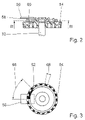
- FIG. 2 shows a schematic partial section through a sensory system having Hall sensors for a rotational position and rotational speed.
- FIG. 3 shows a schematic section according to line III-III in FIG. 2 .
- FIG. 4 shows a schematic partial section through a sensory system having a three-track contact disk for a rotational position and rotational speed.
- FIG. 5 shows a plan view of a three-track contact disk according to FIG. 4 .
- Wiper system 10 includes two wipers 12 , 14 , which sweep over wipe areas 18 , 20 on a windshield 16 of a vehicle (not shown further) in the course of a swiveling motion about their drive shafts 22 , 24 .
- a first wiper motor 26 via its driven shaft 30 , drives drive shaft 22 of wiper 12 on the driver side of the vehicle, while a second wiper motor 28 , by its driven shaft 32 , drives drive shaft 24 of wiper 14 on the passenger side.
- First wiper motor 26 which is designed as reversing motor, has an electronic control unit 34 with control elements 50 to regulate the reversing operation and rotational speed as well as the rotational position of driven shaft 30 and, thereby, of wiper 12 .
- Control elements 50 include means for analyzing the input signals and stored characteristics maps, and a sensory system 36 for detecting the rotational position and rotational speed of driven shaft 30 , such as a micro-controller, an AMR sensor etc.
- Second wiper motor 28 which is designed as a conventional, permanently energized three-brush direct-current motor having one gear step and a rotary motor design, has only one sensory system 36 to detect the absolute and relative rotational position of its driven shaft 32 .
- Wiper motors 26 , 28 are connected to the vehicle electrical system via supply lines 48 .
- Wiper system 10 is activated by an operating lever 38 , sending a signal to control unit 34 via a central electronic system 40 .
- control unit 34 switches a first power stage 44 or a second power stage 46 of second wiper motor 28 , via a power switch 42 , the rotational speed expediently being implemented via the current supply to the brushes.
- Sensory system 36 detects the rotational position of driven shaft 32 of second wiper motor 28 , especially the rotational position corresponding to the parking position of wiper 14 . It also generates counting pulses which may be used to determine an incremental position and the rotational speed. Second wiper motor 28 transmits the generated signals via signal lines 52 to control unit 34 of first wiper motor 26 , which determines from these signals a setpoint value for the rotational position and rotational speed of driven shaft 30 of first wiper motor 26 .
- FIGS. 2 and 3 as well as FIGS. 4 and 5 show two advantageous versions of a sensory system 36 for the rotational position and rotational speed of driven shaft 32 of second wiper motor 28 .
- Driven shaft 32 is driven in a conventional manner by the electric motor via a worm and a worm gear 54 .
- Permanent magnet 62 occupies a segment of approximately 40 degrees and is used to determine the parking position.
- Permanent magnets 64 are evenly distributed over the outer circular path and occupy a small segment 68 .
- Permanent magnet 62 of the inner circular path cooperates with a Hall sensor 60
- permanent magnets 64 of the outer circular path cooperate with a Hall sensor 58 .
- Both Hall sensors are installed on a housing-mounted circuit board 56 and generate a signal as soon as they are passed with little play and a permanent magnet 62 , 64 during a rotary motion of driven shaft 32 or worm gear 54 .
- the signal generated by permanent magnet 62 indicates the parking position of the wiper, whereas permanent magnets 64 generate counting pulses on the outer path, which are analyzed in control unit 34 to detect an incremental position and to determine the rotational speed.
- the design of sensory system 36 according to FIGS. 4 and 5 includes a three-track contact disk 70 which is affixed to worm gear 54 .
- the tracks are configured in a circle and concentrically to the axis of rotation of driven shaft 32 .
- a middle track 80 which is sampled by a slider 74 , has a continuous contact area and is used to supply voltage to sensory system 36 .
- Outer track 78 has a contact area 84 extending over a larger segment, approximately in the range of forty degrees, and cooperates with a slider 72 . When slider 72 touches contact area 84 , the electric circuit to slider 74 is closed and a signal indicating the parking position of wiper 14 is triggered.
- Inner track 82 has a plurality of contact areas 86 distributed over the circumference, which are sampled by a slider 76 and generate counting pulses, which are used to detect the incremental position and to determine the rotational speed of driven shaft 32 .
- Sensory system 36 according to the embodiments shown in FIGS. 2 and 3 as well as in FIGS. 4 and 5 , is inexpensive and does not require additional space.
Landscapes
- Engineering & Computer Science (AREA)
- Mechanical Engineering (AREA)
- Connection Of Motors, Electrical Generators, Mechanical Devices, And The Like (AREA)
- Control Of Electric Motors In General (AREA)
- Control Of Direct Current Motors (AREA)
Applications Claiming Priority (3)
| Application Number | Priority Date | Filing Date | Title |
|---|---|---|---|
| DE10113678.1 | 2001-03-21 | ||
| DE10113678A DE10113678A1 (de) | 2001-03-21 | 2001-03-21 | Wischeranlage mit zwei Scheibenwischern |
| PCT/DE2001/004764 WO2002076796A1 (de) | 2001-03-21 | 2001-12-14 | Wischeranlage mit zwei scheibenwischern |
Publications (2)
| Publication Number | Publication Date |
|---|---|
| US20040008000A1 US20040008000A1 (en) | 2004-01-15 |
| US7256565B2 true US7256565B2 (en) | 2007-08-14 |
Family
ID=7678343
Family Applications (1)
| Application Number | Title | Priority Date | Filing Date |
|---|---|---|---|
| US10/296,008 Expired - Fee Related US7256565B2 (en) | 2001-03-21 | 2001-12-14 | Wiper system using two wipers |
Country Status (8)
| Country | Link |
|---|---|
| US (1) | US7256565B2 (ja) |
| EP (1) | EP1373032B1 (ja) |
| JP (1) | JP4314031B2 (ja) |
| KR (1) | KR100826461B1 (ja) |
| BR (1) | BR0111025B1 (ja) |
| DE (2) | DE10113678A1 (ja) |
| ES (1) | ES2248404T3 (ja) |
| WO (1) | WO2002076796A1 (ja) |
Cited By (28)
| Publication number | Priority date | Publication date | Assignee | Title |
|---|---|---|---|---|
| US20090125183A1 (en) * | 2007-11-13 | 2009-05-14 | Toshiyuki Amagasa | Wiper apparatus control method and wiper control system |
| US20090119865A1 (en) * | 2007-11-13 | 2009-05-14 | Mitsuba Corporation | Opposite-type wiper apparatus |
| US20100084207A1 (en) * | 2008-05-09 | 2010-04-08 | Wyall John C | Controllerless electric drive system |
| USD706200S1 (en) | 2010-09-22 | 2014-06-03 | Pylon Manufacturing Corporation | Windshield wiper cover |
| US8806700B2 (en) | 2011-07-29 | 2014-08-19 | Pylon Manufacturing Corporation | Wiper blade connector |
| US9108595B2 (en) | 2011-07-29 | 2015-08-18 | Pylon Manufacturing Corporation | Windshield wiper connector |
| US9174611B2 (en) | 2011-07-28 | 2015-11-03 | Pylon Manufacturing Corp. | Windshield wiper adapter, connector and assembly |
| US9174609B2 (en) | 2011-04-21 | 2015-11-03 | Pylon Manufacturing Corp. | Wiper blade with cover |
| US9381893B2 (en) | 2011-07-29 | 2016-07-05 | Pylon Manufacturing Corp. | Windshield wiper connector |
| US9457768B2 (en) | 2011-04-21 | 2016-10-04 | Pylon Manufacturing Corp. | Vortex damping wiper blade |
| US9505380B2 (en) | 2014-03-07 | 2016-11-29 | Pylon Manufacturing Corp. | Windshield wiper connector and assembly |
| USD777079S1 (en) | 2014-10-03 | 2017-01-24 | Pylon Manufacturing Corp. | Wiper blade frame |
| USD787308S1 (en) | 2014-10-03 | 2017-05-23 | Pylon Manufacturing Corp. | Wiper blade package |
| US20180186338A1 (en) * | 2015-06-09 | 2018-07-05 | Mitsuba Corporation | Wiper device |
| US10077026B2 (en) | 2012-02-24 | 2018-09-18 | Pylon Manufacturing Corp. | Wiper blade |
| US10166951B2 (en) | 2013-03-15 | 2019-01-01 | Pylon Manufacturing Corp. | Windshield wiper connector |
| US10189445B2 (en) | 2012-02-24 | 2019-01-29 | Pylon Manufacturing Corp. | Wiper blade |
| US10363905B2 (en) | 2015-10-26 | 2019-07-30 | Pylon Manufacturing Corp. | Wiper blade |
| US10513246B2 (en) | 2016-05-19 | 2019-12-24 | Pylon Manufacturing Corp. | Windshield wiper connector |
| US10661759B2 (en) | 2016-05-19 | 2020-05-26 | Pylon Manufacturing Corporation | Windshield wiper connector |
| US10717414B2 (en) | 2016-05-19 | 2020-07-21 | Pylon Manufacturing Corporation | Windshield wiper blade |
| US10723322B2 (en) | 2012-02-24 | 2020-07-28 | Pylon Manufacturing Corp. | Wiper blade with cover |
| US10766462B2 (en) | 2016-05-19 | 2020-09-08 | Pylon Manufacturing Corporation | Windshield wiper connector |
| US10829092B2 (en) | 2012-09-24 | 2020-11-10 | Pylon Manufacturing Corp. | Wiper blade with modular mounting base |
| US10889267B2 (en) * | 2018-03-05 | 2021-01-12 | Tesla, Inc. | Electromagnetic windshield wiper system |
| US11040705B2 (en) | 2016-05-19 | 2021-06-22 | Pylon Manufacturing Corp. | Windshield wiper connector |
| US11407382B2 (en) * | 2019-07-22 | 2022-08-09 | Ford Global Technologies, Llc | Automated vehicle windshield wiper systems for minimizing the buildup of frozen precipitation |
| US11613233B2 (en) | 2021-01-25 | 2023-03-28 | Rosemount Aerospace Inc. | Windshield wiper system with an internal trigger |
Families Citing this family (19)
| Publication number | Priority date | Publication date | Assignee | Title |
|---|---|---|---|---|
| DE10145103B4 (de) * | 2001-09-13 | 2011-08-11 | Robert Bosch GmbH, 70469 | Wischanlage für Fahrzeuge, insbesondere für Automobil-Windschutzscheiben |
| JP4094927B2 (ja) * | 2002-10-09 | 2008-06-04 | 株式会社ミツバ | ワイパ装置の制御方法 |
| JP4047692B2 (ja) * | 2002-10-10 | 2008-02-13 | 株式会社ミツバ | ワイパ装置の制御方法 |
| DE10306495A1 (de) * | 2003-02-17 | 2004-08-26 | Robert Bosch Gmbh | Wischeranlage für Fahrzeug-Windschutzscheiben |
| DE10306496A1 (de) * | 2003-02-17 | 2004-08-26 | Robert Bosch Gmbh | Wischeranlage für Fahrzeug-Windschutzscheiben |
| FR2872756B1 (fr) * | 2004-07-08 | 2006-12-08 | Valeo Systemes Dessuyage | Agencement pour l'essuyage d'un pare brise panoramique |
| DE102005040647A1 (de) * | 2005-08-27 | 2007-03-08 | Valeo Systèmes d`Essuyage | Elektromotorischer Hilfsantrieb für Fahrzeuge |
| DE102005057703A1 (de) * | 2005-12-02 | 2007-06-21 | Daimlerchrysler Ag | Steuergerät mit Wischerschnittstelle |
| DE102009029098A1 (de) * | 2009-09-02 | 2011-03-03 | Robert Bosch Gmbh | Scheibenwischervorrichtung und Verfahren zum Betreiben einer solchen Scheibenwischervorrichtung |
| KR101283254B1 (ko) * | 2011-09-01 | 2013-07-11 | 기아자동차주식회사 | 연료저감을 위한 차량용 발전제어시스템 및 이의 제어방법 |
| US8734191B2 (en) * | 2011-10-06 | 2014-05-27 | Tyco Electronics Corporation | Power connector system |
| CN102616209B (zh) * | 2012-04-12 | 2014-02-26 | 株洲联诚集团有限责任公司 | 一种轨道机车用双气动马达同步刮雨器 |
| CN103759952B (zh) * | 2014-01-26 | 2016-03-23 | 北京长安汽车工程技术研究有限责任公司 | 汽车刮水器的测试装置及方法 |
| IT201800005054A1 (it) * | 2018-05-03 | 2019-11-03 | Sistema di azionamento per un impianto tergicristallo e impianto tergicristallo | |
| KR102697035B1 (ko) * | 2018-07-30 | 2024-08-22 | 엘지전자 주식회사 | 청소기의 노즐 및 그 제어방법 |
| CN109733332A (zh) * | 2019-02-26 | 2019-05-10 | 浙江开拓汽车电器有限公司 | 汽车雨刮器的雨刮电机控制装置及其控制方法 |
| DE102020206966A1 (de) | 2020-06-04 | 2021-12-09 | Robert Bosch Gesellschaft mit beschränkter Haftung | Wischervorrichtung und Getrieberadeinheit |
| US11722036B2 (en) | 2021-06-14 | 2023-08-08 | Commercial Vehicle Group, Inc. | Wiper motors and methods of manufacture and use thereof |
| CN120902016A (zh) * | 2025-08-22 | 2025-11-07 | 工博士机器人技术有限公司 | 特种人形机器人 |
Citations (19)
| Publication number | Priority date | Publication date | Assignee | Title |
|---|---|---|---|---|
| DE3208121A1 (de) | 1982-03-06 | 1983-09-08 | Robert Bosch Gmbh, 7000 Stuttgart | Scheibenwischvorrichtung fuer fahrzeuge |
| DE3248118A1 (de) | 1982-12-24 | 1984-06-28 | SWF-Spezialfabrik für Autozubehör Gustav Rau GmbH, 7120 Bietigheim-Bissingen | Scheibenwischeranlage fuer kraftfahrzeuge |
| US4723101A (en) * | 1985-04-11 | 1988-02-02 | Swf Auto-Electric Gmbh | Windshield wiper system |
| US4900996A (en) * | 1989-06-26 | 1990-02-13 | General Motors Corporation | Vehicle window wipers with dynamic symmetrical overlap |
| US5023467A (en) * | 1987-03-17 | 1991-06-11 | Doduco Gmbh & Co. Dr. Eugen Durrwachter | Method and an interval switch comprising a circuit arrangement for controlling the interval of time between wiping movements of wipers in vehicles |
| DE4125268A1 (de) | 1990-11-29 | 1992-06-04 | Asmo Co Ltd | Scheibenwischanordnung |
| US5331257A (en) * | 1991-12-06 | 1994-07-19 | Valeo Systemes D'essuyage | Commutated electro-dynamic machine such as a d.c. motor, having an auto-synchronizing sensor, and a screen wiping apparatus employing such a motor |
| DE4428543A1 (de) | 1994-08-12 | 1996-02-15 | Kostal Leopold Gmbh & Co Kg | Verstellsystem |
| US5561882A (en) * | 1992-09-15 | 1996-10-08 | Valeo Systemes D'essuyage | Washing and wiping apparatus for a vehicle windshield |
| US5568026A (en) | 1995-03-07 | 1996-10-22 | United Technologies Motor Systems, Inc. | Synchronizing windshield wipers |
| DE19634559A1 (de) | 1996-08-27 | 1998-03-05 | Teves Gmbh Alfred | Scheibenwischvorrichtung |
| EP0952054A2 (en) | 1998-04-22 | 1999-10-27 | Mitsuba Corporation | A method of controlling an opposed type wiper apparatus and a control apparatus thereof |
| FR2785246A1 (fr) | 1998-10-29 | 2000-05-05 | Valeo Systemes Dessuyage | Procede de commande d'un essuie-glace de vehicule |
| US6147466A (en) * | 1998-12-30 | 2000-11-14 | Commercial Vehicle Systems, Inc. | Synchronization system for motors |
| US6281649B1 (en) * | 1997-01-03 | 2001-08-28 | Mccord Winn Textron Inc. | Windshield wiper system |
| US6288509B1 (en) * | 1998-04-22 | 2001-09-11 | Mitsuba Corporation | Method for controlling an opposed wiping type wiper apparatus and an opposed wiping type wiper apparatus |
| US6400110B1 (en) * | 1999-05-31 | 2002-06-04 | Yazaki Corporation | Wiper control apparatus |
| US6425160B1 (en) * | 1999-10-13 | 2002-07-30 | Saito Motors Co., Ltd. | Intermittent driving apparatus for rotary window cleaner |
| US6867559B2 (en) * | 2001-09-13 | 2005-03-15 | Robert Bosch Gmbh | Wiper arrangement for motor vehicles, especially for car windscreens |
-
2001
- 2001-03-21 DE DE10113678A patent/DE10113678A1/de not_active Ceased
- 2001-12-14 JP JP2002575276A patent/JP4314031B2/ja not_active Expired - Fee Related
- 2001-12-14 BR BRPI0111025-0A patent/BR0111025B1/pt not_active IP Right Cessation
- 2001-12-14 KR KR1020027015723A patent/KR100826461B1/ko not_active Expired - Fee Related
- 2001-12-14 ES ES01984715T patent/ES2248404T3/es not_active Expired - Lifetime
- 2001-12-14 EP EP01984715A patent/EP1373032B1/de not_active Expired - Lifetime
- 2001-12-14 WO PCT/DE2001/004764 patent/WO2002076796A1/de not_active Ceased
- 2001-12-14 US US10/296,008 patent/US7256565B2/en not_active Expired - Fee Related
- 2001-12-14 DE DE50107157T patent/DE50107157D1/de not_active Expired - Lifetime
Patent Citations (22)
| Publication number | Priority date | Publication date | Assignee | Title |
|---|---|---|---|---|
| DE3208121A1 (de) | 1982-03-06 | 1983-09-08 | Robert Bosch Gmbh, 7000 Stuttgart | Scheibenwischvorrichtung fuer fahrzeuge |
| DE3248118A1 (de) | 1982-12-24 | 1984-06-28 | SWF-Spezialfabrik für Autozubehör Gustav Rau GmbH, 7120 Bietigheim-Bissingen | Scheibenwischeranlage fuer kraftfahrzeuge |
| US4585980A (en) * | 1982-12-24 | 1986-04-29 | Itt Industries, Inc. | Windshield wiper control |
| US4723101A (en) * | 1985-04-11 | 1988-02-02 | Swf Auto-Electric Gmbh | Windshield wiper system |
| US5023467A (en) * | 1987-03-17 | 1991-06-11 | Doduco Gmbh & Co. Dr. Eugen Durrwachter | Method and an interval switch comprising a circuit arrangement for controlling the interval of time between wiping movements of wipers in vehicles |
| US4900996A (en) * | 1989-06-26 | 1990-02-13 | General Motors Corporation | Vehicle window wipers with dynamic symmetrical overlap |
| DE4125268A1 (de) | 1990-11-29 | 1992-06-04 | Asmo Co Ltd | Scheibenwischanordnung |
| US5256950A (en) * | 1990-11-29 | 1993-10-26 | Asmo Co., Ltd. | Windshield wiper assembly and synchronous signal generating device for windshield wiper |
| US5331257A (en) * | 1991-12-06 | 1994-07-19 | Valeo Systemes D'essuyage | Commutated electro-dynamic machine such as a d.c. motor, having an auto-synchronizing sensor, and a screen wiping apparatus employing such a motor |
| US5561882A (en) * | 1992-09-15 | 1996-10-08 | Valeo Systemes D'essuyage | Washing and wiping apparatus for a vehicle windshield |
| DE4428543A1 (de) | 1994-08-12 | 1996-02-15 | Kostal Leopold Gmbh & Co Kg | Verstellsystem |
| US5568026A (en) | 1995-03-07 | 1996-10-22 | United Technologies Motor Systems, Inc. | Synchronizing windshield wipers |
| DE19634559A1 (de) | 1996-08-27 | 1998-03-05 | Teves Gmbh Alfred | Scheibenwischvorrichtung |
| US6281649B1 (en) * | 1997-01-03 | 2001-08-28 | Mccord Winn Textron Inc. | Windshield wiper system |
| EP0952054A2 (en) | 1998-04-22 | 1999-10-27 | Mitsuba Corporation | A method of controlling an opposed type wiper apparatus and a control apparatus thereof |
| US6107766A (en) * | 1998-04-22 | 2000-08-22 | Mitsuba Corporation | Method of controlling an opposed type wiper apparatus and a control apparatus thereof |
| US6288509B1 (en) * | 1998-04-22 | 2001-09-11 | Mitsuba Corporation | Method for controlling an opposed wiping type wiper apparatus and an opposed wiping type wiper apparatus |
| FR2785246A1 (fr) | 1998-10-29 | 2000-05-05 | Valeo Systemes Dessuyage | Procede de commande d'un essuie-glace de vehicule |
| US6147466A (en) * | 1998-12-30 | 2000-11-14 | Commercial Vehicle Systems, Inc. | Synchronization system for motors |
| US6400110B1 (en) * | 1999-05-31 | 2002-06-04 | Yazaki Corporation | Wiper control apparatus |
| US6425160B1 (en) * | 1999-10-13 | 2002-07-30 | Saito Motors Co., Ltd. | Intermittent driving apparatus for rotary window cleaner |
| US6867559B2 (en) * | 2001-09-13 | 2005-03-15 | Robert Bosch Gmbh | Wiper arrangement for motor vehicles, especially for car windscreens |
Cited By (45)
| Publication number | Priority date | Publication date | Assignee | Title |
|---|---|---|---|---|
| US20090119865A1 (en) * | 2007-11-13 | 2009-05-14 | Mitsuba Corporation | Opposite-type wiper apparatus |
| US7895701B2 (en) * | 2007-11-13 | 2011-03-01 | Mitsuba Corporation | Opposite-type wiper apparatus |
| US8112197B2 (en) * | 2007-11-13 | 2012-02-07 | Mitsuba Corporation | Wiper apparatus control method and wiper control system |
| US20090125183A1 (en) * | 2007-11-13 | 2009-05-14 | Toshiyuki Amagasa | Wiper apparatus control method and wiper control system |
| US20100084207A1 (en) * | 2008-05-09 | 2010-04-08 | Wyall John C | Controllerless electric drive system |
| US10543813B2 (en) | 2010-02-10 | 2020-01-28 | Pylon Manufacturing Corp. | Wiper blade |
| USD706200S1 (en) | 2010-09-22 | 2014-06-03 | Pylon Manufacturing Corporation | Windshield wiper cover |
| US10005431B2 (en) | 2011-04-21 | 2018-06-26 | Pylon Manufacturing Corp. | Vortex damping wiper blade |
| US11124158B2 (en) | 2011-04-21 | 2021-09-21 | Pylon Manufacturing Corp. | Wiper blade with cover |
| US10464533B2 (en) | 2011-04-21 | 2019-11-05 | Pylon Manufacturing Corp. | Wiper blade with cover |
| US9174609B2 (en) | 2011-04-21 | 2015-11-03 | Pylon Manufacturing Corp. | Wiper blade with cover |
| US9457768B2 (en) | 2011-04-21 | 2016-10-04 | Pylon Manufacturing Corp. | Vortex damping wiper blade |
| US10457252B2 (en) | 2011-07-28 | 2019-10-29 | Pylon Manufacturing Corp. | Windshield wiper adapter, connector and assembly |
| US9174611B2 (en) | 2011-07-28 | 2015-11-03 | Pylon Manufacturing Corp. | Windshield wiper adapter, connector and assembly |
| US9381893B2 (en) | 2011-07-29 | 2016-07-05 | Pylon Manufacturing Corp. | Windshield wiper connector |
| US8806700B2 (en) | 2011-07-29 | 2014-08-19 | Pylon Manufacturing Corporation | Wiper blade connector |
| US10597004B2 (en) | 2011-07-29 | 2020-03-24 | Pylon Manufacturing Corporation | Windshield wiper connector |
| US9108595B2 (en) | 2011-07-29 | 2015-08-18 | Pylon Manufacturing Corporation | Windshield wiper connector |
| US11180118B2 (en) | 2012-02-24 | 2021-11-23 | Pylon Manufacturing Corp. | Wiper blade |
| US10189445B2 (en) | 2012-02-24 | 2019-01-29 | Pylon Manufacturing Corp. | Wiper blade |
| US10077026B2 (en) | 2012-02-24 | 2018-09-18 | Pylon Manufacturing Corp. | Wiper blade |
| US11136002B2 (en) | 2012-02-24 | 2021-10-05 | Pylon Manufacturing Corp. | Wiper blade |
| US10723322B2 (en) | 2012-02-24 | 2020-07-28 | Pylon Manufacturing Corp. | Wiper blade with cover |
| US10829092B2 (en) | 2012-09-24 | 2020-11-10 | Pylon Manufacturing Corp. | Wiper blade with modular mounting base |
| US10166951B2 (en) | 2013-03-15 | 2019-01-01 | Pylon Manufacturing Corp. | Windshield wiper connector |
| US9505380B2 (en) | 2014-03-07 | 2016-11-29 | Pylon Manufacturing Corp. | Windshield wiper connector and assembly |
| US9889822B2 (en) | 2014-03-07 | 2018-02-13 | Pylon Manufacturing Corp. | Windshield wiper connector and assembly |
| USD777079S1 (en) | 2014-10-03 | 2017-01-24 | Pylon Manufacturing Corp. | Wiper blade frame |
| USD787308S1 (en) | 2014-10-03 | 2017-05-23 | Pylon Manufacturing Corp. | Wiper blade package |
| US20180186338A1 (en) * | 2015-06-09 | 2018-07-05 | Mitsuba Corporation | Wiper device |
| US10583808B2 (en) * | 2015-06-09 | 2020-03-10 | Mitsuba Corporation | Wiper device |
| US11155241B2 (en) | 2015-10-26 | 2021-10-26 | Pylon Manufacturing Corp. | Windshield wiper blade |
| US10363905B2 (en) | 2015-10-26 | 2019-07-30 | Pylon Manufacturing Corp. | Wiper blade |
| US10717414B2 (en) | 2016-05-19 | 2020-07-21 | Pylon Manufacturing Corporation | Windshield wiper blade |
| US11040705B2 (en) | 2016-05-19 | 2021-06-22 | Pylon Manufacturing Corp. | Windshield wiper connector |
| US10766462B2 (en) | 2016-05-19 | 2020-09-08 | Pylon Manufacturing Corporation | Windshield wiper connector |
| US10661759B2 (en) | 2016-05-19 | 2020-05-26 | Pylon Manufacturing Corporation | Windshield wiper connector |
| US10513246B2 (en) | 2016-05-19 | 2019-12-24 | Pylon Manufacturing Corp. | Windshield wiper connector |
| US11554754B2 (en) | 2016-05-19 | 2023-01-17 | Pylon Manufacturing Corporation | Windshield wiper blade |
| US10889267B2 (en) * | 2018-03-05 | 2021-01-12 | Tesla, Inc. | Electromagnetic windshield wiper system |
| US11541846B2 (en) | 2018-03-05 | 2023-01-03 | Tesla, Inc. | Electromagnetic windshield wiper system |
| US11407382B2 (en) * | 2019-07-22 | 2022-08-09 | Ford Global Technologies, Llc | Automated vehicle windshield wiper systems for minimizing the buildup of frozen precipitation |
| US20220324416A1 (en) * | 2019-07-22 | 2022-10-13 | Ford Global Technologies, Llc | Automated vehicle windshield wiper systems for minimizing the buildup of frozen precipitation |
| US11766995B2 (en) * | 2019-07-22 | 2023-09-26 | Ford Global Technologies, Llc | Automated vehicle windshield wiper systems for minimizing the buildup of frozen precipitation |
| US11613233B2 (en) | 2021-01-25 | 2023-03-28 | Rosemount Aerospace Inc. | Windshield wiper system with an internal trigger |
Also Published As
| Publication number | Publication date |
|---|---|
| JP4314031B2 (ja) | 2009-08-12 |
| DE50107157D1 (de) | 2005-09-22 |
| ES2248404T3 (es) | 2006-03-16 |
| KR100826461B1 (ko) | 2008-05-02 |
| BR0111025B1 (pt) | 2011-02-08 |
| US20040008000A1 (en) | 2004-01-15 |
| DE10113678A1 (de) | 2002-10-02 |
| BR0111025A (pt) | 2005-05-10 |
| KR20030009499A (ko) | 2003-01-29 |
| EP1373032B1 (de) | 2005-08-17 |
| WO2002076796A1 (de) | 2002-10-03 |
| JP2004521004A (ja) | 2004-07-15 |
| EP1373032A1 (de) | 2004-01-02 |
Similar Documents
| Publication | Publication Date | Title |
|---|---|---|
| US7256565B2 (en) | Wiper system using two wipers | |
| US6944906B2 (en) | Direct drive windshield wiper assembly | |
| KR101337098B1 (ko) | 직접 구동식 윈드쉴드 와이퍼 조립체 | |
| US5157314A (en) | Windshield wiping system for motor vehicles | |
| JP6349120B2 (ja) | ワイパシステム制御方法及びワイパシステム制御装置 | |
| US8453290B2 (en) | Wiper driving apparatus | |
| WO2005025950A2 (en) | Reversing-motor windshield wiper system | |
| JP2002524335A (ja) | ワイパ駆動装置 | |
| US7392565B2 (en) | Tandem windshield wiper system with bellcrank linkage | |
| KR101190895B1 (ko) | 직접 구동 모터를 구비한 탠덤식 윈드쉴드 와이퍼 시스템 | |
| US6867559B2 (en) | Wiper arrangement for motor vehicles, especially for car windscreens | |
| KR20000023243A (ko) | 자동차용 윈드실드 와이퍼 | |
| US10005430B2 (en) | Wiper apparatus | |
| JP2009067261A (ja) | ワイパシステム及びワイパ制御方法 | |
| US5754020A (en) | Wiper-washer system for vehicles | |
| US6396230B1 (en) | Windshield wiper device | |
| JP5107298B2 (ja) | ワイパースイッチ装置 | |
| JP7763387B2 (ja) | 払拭装置 | |
| KR20050036569A (ko) | 차량의 와이퍼 구동장치 | |
| JPH04356254A (ja) | ウインドシールドワイパ | |
| KR20080048217A (ko) | 자동차용 와이퍼 파킹위치 제어시스템 | |
| KR19980056072A (ko) | 와이퍼 모터 회전속도 제어 시스템 | |
| JP2003219673A (ja) | モータ制御装置 |
Legal Events
| Date | Code | Title | Description |
|---|---|---|---|
| AS | Assignment |
Owner name: ROBERT BOSCH GMBH, GERMANY Free format text: ASSIGNMENT OF ASSIGNORS INTEREST;ASSIGNORS:MERKEL, WILFRIELD;MICHENFELDER, GEBHARD;FLEISCHER, CLAUS;REEL/FRAME:014209/0935;SIGNING DATES FROM 20030602 TO 20030610 |
|
| STCF | Information on status: patent grant |
Free format text: PATENTED CASE |
|
| FPAY | Fee payment |
Year of fee payment: 4 |
|
| FPAY | Fee payment |
Year of fee payment: 8 |
|
| FEPP | Fee payment procedure |
Free format text: MAINTENANCE FEE REMINDER MAILED (ORIGINAL EVENT CODE: REM.); ENTITY STATUS OF PATENT OWNER: LARGE ENTITY |
|
| LAPS | Lapse for failure to pay maintenance fees |
Free format text: PATENT EXPIRED FOR FAILURE TO PAY MAINTENANCE FEES (ORIGINAL EVENT CODE: EXP.); ENTITY STATUS OF PATENT OWNER: LARGE ENTITY |
|
| STCH | Information on status: patent discontinuation |
Free format text: PATENT EXPIRED DUE TO NONPAYMENT OF MAINTENANCE FEES UNDER 37 CFR 1.362 |
|
| FP | Lapsed due to failure to pay maintenance fee |
Effective date: 20190814 |