US7280856B2 - Portable terminal having tuner for changing radiation pattern - Google Patents
Portable terminal having tuner for changing radiation pattern Download PDFInfo
- Publication number
- US7280856B2 US7280856B2 US10/834,737 US83473704A US7280856B2 US 7280856 B2 US7280856 B2 US 7280856B2 US 83473704 A US83473704 A US 83473704A US 7280856 B2 US7280856 B2 US 7280856B2
- Authority
- US
- United States
- Prior art keywords
- tuner
- portable terminal
- main body
- folder
- antenna
- Prior art date
- Legal status (The legal status is an assumption and is not a legal conclusion. Google has not performed a legal analysis and makes no representation as to the accuracy of the status listed.)
- Expired - Lifetime, expires
Links
Images




Classifications
-
- H—ELECTRICITY
- H01—ELECTRIC ELEMENTS
- H01Q—ANTENNAS, i.e. RADIO AERIALS
- H01Q1/00—Details of, or arrangements associated with, antennas
- H01Q1/12—Supports; Mounting means
- H01Q1/22—Supports; Mounting means by structural association with other equipment or articles
- H01Q1/24—Supports; Mounting means by structural association with other equipment or articles with receiving set
- H01Q1/241—Supports; Mounting means by structural association with other equipment or articles with receiving set used in mobile communications, e.g. GSM
-
- H—ELECTRICITY
- H01—ELECTRIC ELEMENTS
- H01Q—ANTENNAS, i.e. RADIO AERIALS
- H01Q19/00—Combinations of primary active antenna elements and units with secondary devices, e.g. with quasi-optical devices, for giving the antenna a desired directional characteristic
- H01Q19/005—Patch antenna using one or more coplanar parasitic elements
-
- H—ELECTRICITY
- H04—ELECTRIC COMMUNICATION TECHNIQUE
- H04B—TRANSMISSION
- H04B1/00—Details of transmission systems, not covered by a single one of groups H04B3/00 - H04B13/00; Details of transmission systems not characterised by the medium used for transmission
- H04B1/38—Transceivers, i.e. devices in which transmitter and receiver form a structural unit and in which at least one part is used for functions of transmitting and receiving
- H04B1/3827—Portable transceivers
- H04B1/3833—Hand-held transceivers
- H04B1/3838—Arrangements for reducing RF exposure to the user, e.g. by changing the shape of the transceiver while in use
-
- H—ELECTRICITY
- H04—ELECTRIC COMMUNICATION TECHNIQUE
- H04M—TELEPHONIC COMMUNICATION
- H04M1/00—Substation equipment, e.g. for use by subscribers
- H04M1/02—Constructional features of telephone sets
- H04M1/0202—Portable telephone sets, e.g. cordless phones, mobile phones or bar type handsets
- H04M1/0206—Portable telephones comprising a plurality of mechanically joined movable body parts, e.g. hinged housings
- H04M1/0208—Portable telephones comprising a plurality of mechanically joined movable body parts, e.g. hinged housings characterized by the relative motions of the body parts
- H04M1/0214—Foldable telephones, i.e. with body parts pivoting to an open position around an axis parallel to the plane they define in closed position
- H04M1/0216—Foldable in one direction, i.e. using a one degree of freedom hinge
Definitions
- the present invention relates generally to a portable terminal having a tuner, and in particular, to a portable terminal having a tuner for changing an antenna radiation pattern by changing the current distribution of a ground provided to the portable terminal.
- portable terminals are equipped with a variety of functions owing to the development of information communication technology, the trend for providing terminals of smaller size, of lighter weight and of improved portability.
- the portable terminals were confined to voice call, short message transmission, and the like, whereas they are becoming capable of transmitting/receiving multimedia data such as moving pictures provided by service providers, video conferencing via a wireless Internet, and moving picture mail.
- a portable terminal is a unit that allows a user to wirelessly communicate with another party.
- Portable terminals include HHP (Hand Held Products), CT-2 (Cordless Telephone-2) cellular phones, smart phones, digital phones, PCS (Personal Communication Service) phones, PDAs (Personal Digital Assistants), and laptop computers, typically categorized according to their appearance.
- the portable terminals usually use an LCD (Liquid Crystal Display) as a data output device.
- LCD Liquid Crystal Display
- a keypad a basic data input device, is provided via an arrangement of keys.
- An antenna device is positioned appropriately for receiving a signal. Providing increased efficiency and, as more recently has become an issue, reduced SAR (Specific Absorption Rate) are challenging issues in designing the antenna device.
- whip antenna For applications to conventional portable terminals, whip antenna, helical antenna, sleeve antenna, N-type antenna, chip antenna, and FS-PIFA antenna are provided at the outside of the portable terminal. Thus, these antennas are called external antennas.
- inverted F antenna planar inverted F antenna (PIFA), diversity antenna, microstrip antenna, twisted loop antenna, and EID (Electronic Identification) antenna are internal antennas that can be installed within the portable terminals.
- PIFA planar inverted F antenna
- EID Electronic Identification
- Antennas utilized in portable terminals can also be divided into monopole or planar types according to how they excite radiated electromagnetic waves.
- Monopole type antennas include whip antenna, helical antenna, sleeve antenna, chip antenna, and N-type antenna
- planar type antennas include inverted F antenna, PIFA, diversity antenna, microstrip antenna, EID antenna, FS (FireStick)-PIFA, and RCDLA (Radiation Coupled Dual L-Antenna).
- the monopole antennas can create strong electromagnetic waves that have been alleged to adversely affect the human body. While it is easy to suppress the effects of electromagnetic waves from the planar antennas, these antennas do not have wide bands.
- monopole antennas are external ones
- recently developed antennas include a half-exposed, fixed monopole antenna, an internal monopole antenna with an electromagnetic wave absorber, as well as a SAR-reducing monopole antenna for a folder-type terminal, which have internal structures, operate in wide bands, and provides a low SAR.
- the half-exposed, fixed monopole antenna provide excellent antenna efficiency, but is not as effective in reducing SAR as the wave absorbing internal monopole antenna. To the contrary, although the wave absorbing internal monopole antenna reduces SAR more effectively than the half-exposed, fixed monopole antenna, it has lower antenna efficiency.
- the monopole antenna designed for SAR reduction in a folder-type terminal which was proposed to overcome the above problems, is excellent in both antenna efficiency and SAR reduction.
- an electromagnetic wave absorber is positioned in the vicinity of a hinge device that connects two terminal bodies, electromagnetic wave leakage in the hinge device may lead to a SAR increase.
- a folder-type portable terminal comprises a main body 10 having a plurality of keys 11 which are pressed to enter intended data and a microphone 12 , a folder 20 having a main LCD 21 , a sub LCD 24 for displaying input data, a speaker 22 , a PCB 23 in the folder 20 and a hinge device 30 which connects the body 10 and the folder 20 along a hinge axis A 1 and is rotatable so that the folder 20 advances toward or recedes away from the body 10 .
- the width of the folder 20 is relatively made wide as compared to its length, or the hinge axis A 1 is defined near an antenna device 40 on the main body 10 , for sake of fabrication convenience.
- electromagnetic waves from a power supply for the antenna can leak in the hinge device 30 , which is positioned between the main body 10 and the folder 20 , thereby increasing SAR.
- the antenna is a monopole antenna
- a ground surface perpendicular to an antenna element is needed within an upper portion of the main body 10 .
- a sufficient antenna ground area is difficult to ensure and reduction of the thickness of the portable terminal is limited.
- a SAR-reducing folder-type terminal has been developed. It has the same configuration as the conventional folder-type portable terminal, except that an electromagnetic wave reflecting plate is attached on the inner or outer surface of the folder 20 such that it faces the antenna device when the folder 20 is opened.
- the antenna can be a helical antenna, a whip antenna, or a half-exposed, fixed monopole antenna.
- Use the half-exposed, fixed monopole antenna allows the antenna ground surface to be easily obtained by the reflecting plate. If the antenna ground surface must be secured on the upper surface of the main body by using the whip or helical antenna, the ground surface itself will be narrow.
- Folder-type portable terminals typically have a ground larger than 1 ⁇ 4 ⁇ of its operating frequency, e.g. 1800 MHz.
- the ground refers to a part of the main body or folder where electrical current flows.
- a radiation pattern can greatly vary. Because there is no specific solution for SAR reduction, SAR, reduction, attempts have been made to reduce SAR by lowering antenna output, thereby deteriorating the operation characteristics of the antenna device.
- the radiation pattern of the existing folder-type portable terminal depends predominantly on a limited ground size of the terminal.
- the radiation pattern of the portable terminal affects SAR as well as the operation performance of the terminal.
- Conventional SAR reduction techniques are accompanied by degraded antenna radiation performance, which in turn degrades the operation performance of the portable terminal.
- an object of the present invention is to substantially solve at least the above problems and/or disadvantages and to provide at least the advantages below. Accordingly, an object of the present invention is to provide a portable terminal having a tuner configured for changing an antenna radiation pattern by changing the current distribution of a ground, thereby reducing SAR and improving antenna operation characteristics.
- a main body of the terminal has a main body PCB and a main body ground defined in the main body PCB.
- a folder is rotatably connected to the main body by a hinge device.
- An antenna device is provided at an upper end of the main body.
- a tuner is formed at a predetermined position of the main body in the vicinity of the antenna device, for changing a current distribution of the main body and thus changing an antenna radiation pattern of the portable terminal.
- a folder in a portable terminal, has a folder PCB and a folder ground defined in the folder PCB.
- the folder is rotatably connected to a main body by a hinge device.
- An antenna device is provided at an upper end of the main body.
- a tuner is formed at a predetermined position of the folder in the vicinity of the antenna device, for changing a current distribution of the main body and thus changing an antenna radiation pattern of the portable terminal.
- a main body has side hinge arms at both upper ends thereof
- a folder has a center hinge arm rotatably connected between the side hinge arms and hinged to the main body
- an antenna device protrudes from an upper end of the main body
- a tuner is formed into a predetermined pattern in the center hinge arm, for changing a radiation pattern of the antenna device.
- FIG. 1 is a perspective view illustrating a conventional folder-type portable terminal in an open state
- FIG. 2 is a plan view of a the conventional folder-type portable terminal in a closed state
- FIG. 3 is a view of the interior structure of a folder in the conventional folder-type portable terminal illustrated in FIG. 2 ;
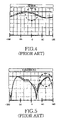
- FIG. 4 is a graph illustrating the azimuth radiation pattern of the conventional folder-type portable terminal illustrated in FIG. 1 ;
- FIG. 5 is a graph illustrating an elevation (E1) radiation pattern of the conventional folder-type portable terminal illustrated in FIG. 1 ;
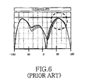
- FIG. 6 is a graph illustrating an elevation (E2) radiation pattern of the conventional folder-type portable terminal illustrated in FIG. 1 ;
- FIG. 7 is a view of the interior structure of the main body showing a preferred embodiment of the present invention.
- FIG. 8 is an enlarged view of a portion “A” illustrated in FIG. 7 ;
- FIG. 9 is a side sectional view illustrating an embodiment of a tuner mounted on a main body PCB (Printed Circuit Board) in the main body of the portable terminal illustrated in FIG. 7 ;
- PCB Print Circuit Board
- FIG. 10 is a side sectional view illustrating another embodiment of a tuner mounted under the main body PCB in the main body of the portable terminal illustrated in FIG. 7 ;
- FIG. 11 is a view of the interior structure of the main body showing another embodiment of the pattern of the tuner
- FIG. 12 illustrates another pattern of the tuner in the main body of the portable terminal illustrated in FIG. 7 ;
- FIG. 13 is a graph illustrating the azimuth radiation pattern of the portable terminal illustrated in FIG. 7 ;
- FIG. 14 is a graph illustrating an E1 radiation pattern of the portable terminal illustrated in FIG. 7 ;
- FIG. 15 is a graph illustrating an E2 radiation pattern of the portable terminal illustrated in FIG. 7 ;
- FIG. 16 illustrates the interior structure of a folder of a portable terminal having a tuner pattern according to another preferred embodiment of the present invention
- FIG. 17 is an enlarged view of a portion “B” illustrated in FIG. 16 ;
- FIG. 18 is an exploded perspective view illustrating the folder of the portable terminal illustrated in FIG. 16 ;
- FIG. 19 illustrates an alternative pattern of a tuner in the folder of the portable terminal illustrated in FIG. 16 ;
- FIG. 20 illustrates another pattern of the tuner in the folder of the portable terminal illustrated in FIG. 16 ;
- FIG. 21 is a graph illustrating the azimuth radiation pattern of the portable terminal illustrated in FIG. 16 ;
- FIG. 22 is a graph illustrating an E1 radiation pattern of the portable terminal illustrated in FIG. 16 ;
- FIG. 23 is a graph illustrating an E2 radiation pattern of the portable terminal illustrated in FIG. 16 .
- portable terminals comprise the main body 10 having a PCB 13 and a ground 400 defined in the PCB 13 , and the folder 20 having a PCB 23 and a ground 4000 defined in the PCB 23 .
- the hinge device 30 is provided at an end of the main body 10 , for connecting the main body 10 to the folder 20 .
- the antenna device 40 is installed at an appropriate position on an upper end of the main body 10 .
- a tuner 100 is disposed within the main body 10 , in the vicinity of the antenna device 40 , for concurrently changing the current distribution of the main body ground 400 and the antenna radiation pattern of the main body 10 .
- the tuner 100 preferably has an “F” or a “P” shape.
- the tuner 100 is provided, at an end 101 thereof, with a connector 300 that comes into contact with a grounding portion 13 a of the main body ground 400 .
- the other end 102 of the tuner 100 is remote, i.e. positioned away, from the grounding portion 13 a and is positioned in the end of main body 10 to closest to the antenna device 40 .
- the tuner 100 can be formed in a predetermined pattern using a conductive paint so that it is easily connected to the grounding portion 13 a of the main body ground 400 . Also, the tuner 100 may be formed of a metal to easily change the current distribution of the main body ground 400 .
- the tuner 100 is provided on the top surface or bottom surface of the main body PCB 13 .
- the top or bottom surfaces of the main body PCB 13 respectively correspond to the surface that is away from or closer to the antenna 40 .
- the tuner 100 changes the current distribution of the main body ground 400 and thus changes the antenna radiation pattern of the terminal. At the same time, the tuner 100 reduces SAR and improves antenna operation characteristics, i.e. field performance. Tuning can be carried out such that the antenna radiation pattern is changed by controlling the pattern of the tuner 100 , that is, the length or structure of the tuner 100 .
- the tuner 100 can be formed in a “P” shape or an “F” shape, respectively.
- an F-shaped tuner 200 is provided, at end 201 thereof, with the connector 300 .
- the other two ends 202 of the tuner 200 are extended in parallel with each other along the length of the hinge device 30 such that they are remote, i.e. positioned away, from the grounding portion 13 a and are positioned in the same end of main body 10 as the antenna device 40 .
- FIG. 13 is a graph illustrating an azimuth radiation pattern of the portable terminal having the tuner 100 according to the embodiment of the present invention.
- the direction of zero degrees (0) indicated on the abscissa is a direction toward the user's head.
- Comparison with the azimuth radiation pattern of the conventional portable terminals which lack a tuner, as illustrated in FIG. 4 reveals that the portable terminal having the tuner 100 radiates less electromagnetic energy toward the human body.
- FIGS. 14 and 15 are graphs illustrating elevations E1 and E2 radiation patterns of the portable terminal with the tuner 100 according to the first embodiment of the present invention.
- a range between of 90 to 150 in the elevation patterns corresponds to the direction toward the human body.
- Comparison with the E1 and E2 radiation patterns of the conventional portable terminals which lack a tuner, as illustrated in FIGS. 5 and 6 reveals that portable terminals having the tuner 100 radiate less electromagnetic energy toward the human body.
- the portable terminal comprises a tuner 1000 positioned at an end of the folder 20 .
- the tuner 1000 changes the current distribution of a folder ground 4000 defined in the folder 20 and thus changes the antenna radiation pattern of the terminal. At the same time, it reduces SAR and improves field performance.
- the tuner 1000 is preferably disposed in the vicinity of the antenna 40 .
- the tuner 1000 is provided, at an end 1001 thereof, with a connector 3000 that comes into contact with a grounding portion 23 a of the folder ground 4000 defined on the antenna frame or the folder PCB 23 .
- the other end 1002 of the tuner 1000 is disposed remote from the grounding portion 23 a and is positioned in the end of folder 20 closest to the antenna device 40 .
- the length or structure of the tuner 1000 is adjusted depending on the change of the antenna radiation pattern.
- FIG. 18 is an exploded perspective view illustrating the tuner 1000 illustrated in FIG. 16 mounted on the folder 20 .
- the tuner 1000 is formed into a predetermined pattern within a center hinge arm 35 formed at an end of the folder 20 .
- the folder 20 is provided with a front case 20 a and a rear case 20 b attached to the rear of the front case 20 a.
- the front case 20 a faces the main body 10 when the folder 20 is hingeably closed to the main body 10 .
- the front case 20 a is provided, at an end thereof, with the center hinge arm 35 .
- An outer circumferential portion of the center hinge arm 35 is covered with the rear case 20 b.
- the tuner 1000 is positioned within the center hinge arm 35 and, more specifically, extends along the hinge axis A 1 at the outer circumferential portion of the center hinge arm 35 , which is covered with the rear case 20 b. While the tuner 1000 is preferably formed by coating a portion of the center hinge arm 35 of the folder 20 with a conductive paint, alternative embodiments of the present invention can utilize a conductive cloth tape or an attachable metal pattern.
- the tuner 1000 is preferably connected to a ground line of the folder PCB 23 or to a conductive spray coated in the folder 20 .
- the tuner 1000 having the above-described configuration expands the grounding of the PCB and changes the radiation pattern of the antenna device, thereby reducing SAR.
- the tuner 1000 preferably has an “F” or a “P” shape.
- an F-shaped tuner 2000 is provided, at end 2001 thereof, with the connector 3000 .
- the other two ends 2002 of the tuner 2000 are extended in parallel with each other along the length of the hinge device 30 such that they are remote from the grounding portion 23 a and near to the antenna device 40 .
- FIG. 21 is a graph illustrating an azimuth radiation pattern of the portable terminal having the tuner 1000 according to the second embodiment of the present invention.
- the direction of zero degrees (0) shown on the abscissa is a direction toward the user's head.
- Comparison with the azimuth radiation pattern of the conventional portable terminals which lack a tuner, as illustrated in FIG. 4 reveals that portable terminals having the tuner 1000 radiate less electromagnetic energy toward the human body.
- FIGS. 22 and 23 are graphs illustrating elevations E1 and E2 radiation patterns of the portable terminal with the tuner 1000 according to the second embodiment of the present invention.
- a range between of 90 to 150 in the elevation patterns corresponds to the direction toward the user's body.
- Comparison with the E1 and E2 radiation patterns of the conventional portable terminals which lack a tuner, as illustrated in FIGS. 5 and 6 reveals that portable terminals having the tuner 1000 radiate less electromagnetic energy toward the user's body.
- the tuner 100 (or 1000 ) so as to change the current distribution of the main body 10 and the folder 20 and thus change the antenna radiation pattern
- the current distribution of the terminal and the antenna radiation pattern can be changed to meet a required specification.
- the resulting SAR reduction and improvement of field operation performance improve the antenna performance of the terminal.
- the tuner is positioned in the vicinity of the antenna device to change the current distribution of the ground current in the folder and thus change an antenna radiation pattern. Therefore, SAR is reduced and field operation performance is improved, thereby improving the antenna performance of the terminal.
Landscapes
- Engineering & Computer Science (AREA)
- Computer Networks & Wireless Communication (AREA)
- Signal Processing (AREA)
- Support Of Aerials (AREA)
- Telephone Set Structure (AREA)
Applications Claiming Priority (6)
| Application Number | Priority Date | Filing Date | Title |
|---|---|---|---|
| KRP2003-87754 | 2003-04-12 | ||
| KR20030033198 | 2003-05-24 | ||
| KRP2003-33198 | 2003-05-24 | ||
| KRP2003-52625 | 2003-07-30 | ||
| KR20030052625 | 2003-07-30 | ||
| KR1020030087754A KR100584399B1 (ko) | 2003-05-24 | 2003-12-04 | 방사 패턴 변경용 튜닝부를 구비하는 휴대용 단말기 |
Publications (2)
| Publication Number | Publication Date |
|---|---|
| US20040204027A1 US20040204027A1 (en) | 2004-10-14 |
| US7280856B2 true US7280856B2 (en) | 2007-10-09 |
Family
ID=33135784
Family Applications (1)
| Application Number | Title | Priority Date | Filing Date |
|---|---|---|---|
| US10/834,737 Expired - Lifetime US7280856B2 (en) | 2003-05-24 | 2004-04-29 | Portable terminal having tuner for changing radiation pattern |
Country Status (4)
| Country | Link |
|---|---|
| US (1) | US7280856B2 (de) |
| EP (1) | EP1482646B1 (de) |
| CN (1) | CN1574661A (de) |
| DE (1) | DE602004005101T2 (de) |
Cited By (3)
| Publication number | Priority date | Publication date | Assignee | Title |
|---|---|---|---|---|
| US20050282595A1 (en) * | 2004-06-21 | 2005-12-22 | Spence Michael F | Communication device including one or more electrical control buttons in an upper housing part |
| US20070126642A1 (en) * | 2003-12-09 | 2007-06-07 | Kenji Sato | Folding mobile radio device |
| US20130118780A1 (en) * | 2010-04-12 | 2013-05-16 | Zte Corporation | Wireless terminal with reduced specific absorption rate peak and implementation method thereof |
Families Citing this family (28)
| Publication number | Priority date | Publication date | Assignee | Title |
|---|---|---|---|---|
| US8744384B2 (en) | 2000-07-20 | 2014-06-03 | Blackberry Limited | Tunable microwave devices with auto-adjusting matching circuit |
| KR100539935B1 (ko) * | 2003-08-08 | 2005-12-28 | 삼성전자주식회사 | 휴대 단말기의 그라운드 연결장치 |
| US9406444B2 (en) | 2005-11-14 | 2016-08-02 | Blackberry Limited | Thin film capacitors |
| CN1988252B (zh) * | 2005-12-19 | 2011-05-11 | 环旭电子股份有限公司 | 印刷折疊式天线 |
| US7711337B2 (en) | 2006-01-14 | 2010-05-04 | Paratek Microwave, Inc. | Adaptive impedance matching module (AIMM) control architectures |
| KR100722309B1 (ko) * | 2006-01-20 | 2007-05-28 | 삼성전자주식회사 | 전자파 흡수율 저감 장치 및 그 장치를 포함한이동통신단말기 |
| USD554094S1 (en) * | 2006-03-31 | 2007-10-30 | Motorola, Inc. | Housing for a communication device |
| KR100842081B1 (ko) * | 2006-07-26 | 2008-06-30 | 삼성전자주식회사 | 대역폭이 증가된 모노폴 안테나 및 이를 구비한 이동통신단말기 |
| US7535312B2 (en) | 2006-11-08 | 2009-05-19 | Paratek Microwave, Inc. | Adaptive impedance matching apparatus, system and method with improved dynamic range |
| US7714676B2 (en) | 2006-11-08 | 2010-05-11 | Paratek Microwave, Inc. | Adaptive impedance matching apparatus, system and method |
| US7917104B2 (en) | 2007-04-23 | 2011-03-29 | Paratek Microwave, Inc. | Techniques for improved adaptive impedance matching |
| US7991363B2 (en) | 2007-11-14 | 2011-08-02 | Paratek Microwave, Inc. | Tuning matching circuits for transmitter and receiver bands as a function of transmitter metrics |
| US8072285B2 (en) | 2008-09-24 | 2011-12-06 | Paratek Microwave, Inc. | Methods for tuning an adaptive impedance matching network with a look-up table |
| US9026062B2 (en) | 2009-10-10 | 2015-05-05 | Blackberry Limited | Method and apparatus for managing operations of a communication device |
| US8803631B2 (en) | 2010-03-22 | 2014-08-12 | Blackberry Limited | Method and apparatus for adapting a variable impedance network |
| WO2011133657A2 (en) | 2010-04-20 | 2011-10-27 | Paratek Microwave, Inc. | Method and apparatus for managing interference in a communication device |
| CN101867385B (zh) * | 2010-06-21 | 2013-11-06 | 华为终端有限公司 | 无线通信设备 |
| US8712340B2 (en) | 2011-02-18 | 2014-04-29 | Blackberry Limited | Method and apparatus for radio antenna frequency tuning |
| US8655286B2 (en) | 2011-02-25 | 2014-02-18 | Blackberry Limited | Method and apparatus for tuning a communication device |
| US8594584B2 (en) | 2011-05-16 | 2013-11-26 | Blackberry Limited | Method and apparatus for tuning a communication device |
| US9769826B2 (en) | 2011-08-05 | 2017-09-19 | Blackberry Limited | Method and apparatus for band tuning in a communication device |
| CN103428903B (zh) | 2012-05-16 | 2016-12-21 | 华为终端有限公司 | 无线通信设备和制造无线通信设备的方法 |
| US8948889B2 (en) | 2012-06-01 | 2015-02-03 | Blackberry Limited | Methods and apparatus for tuning circuit components of a communication device |
| US9853363B2 (en) | 2012-07-06 | 2017-12-26 | Blackberry Limited | Methods and apparatus to control mutual coupling between antennas |
| US9350405B2 (en) | 2012-07-19 | 2016-05-24 | Blackberry Limited | Method and apparatus for antenna tuning and power consumption management in a communication device |
| US10404295B2 (en) | 2012-12-21 | 2019-09-03 | Blackberry Limited | Method and apparatus for adjusting the timing of radio antenna tuning |
| US9374113B2 (en) | 2012-12-21 | 2016-06-21 | Blackberry Limited | Method and apparatus for adjusting the timing of radio antenna tuning |
| US9438319B2 (en) | 2014-12-16 | 2016-09-06 | Blackberry Limited | Method and apparatus for antenna selection |
Citations (16)
| Publication number | Priority date | Publication date | Assignee | Title |
|---|---|---|---|---|
| US6246374B1 (en) * | 2000-04-06 | 2001-06-12 | Motorola, Inc. | Passive flip radiator for antenna enhancement |
| US6342859B1 (en) * | 1998-04-20 | 2002-01-29 | Allgon Ab | Ground extension arrangement for coupling to ground means in an antenna system, and an antenna system and a mobile radio device having such ground arrangement |
| US6442377B1 (en) | 1996-11-04 | 2002-08-27 | Telefonaktiebolaget L M Ericsson (Publ) | Radio telephone with high antenna efficiency |
| CN1366439A (zh) | 2001-01-17 | 2002-08-28 | 三星电子株式会社 | 用于在双液晶显示器折叠型移动终端上显示消息的方法 |
| WO2002071534A1 (de) | 2001-03-07 | 2002-09-12 | Siemens Aktiengesellschaft | Funkkommunikationsgerät mit einem sar-wert-reduzierenden korrekturelement |
| DE10134848C1 (de) | 2001-07-17 | 2002-12-12 | Siemens Ag | Mobilfunkgerät mit reduziertem SAR-Wert |
| US20050026660A1 (en) * | 2003-07-30 | 2005-02-03 | Lg Electronics Inc. | System and method for obtaining radiation characteristics of built-in antenna in mobile communication terminal |
| US20050030233A1 (en) * | 2003-08-08 | 2005-02-10 | Samsung Electronics Co., Ltd. | Ground connecting apparatus for mobile terminal |
| US6885880B1 (en) * | 2000-09-22 | 2005-04-26 | Teleponaktiebolaget Lm Ericsson (Publ.) | Inverted-F antenna for flip-style mobile terminals |
| US6898282B2 (en) * | 2000-01-17 | 2005-05-24 | Samsung Electronics Co., Ltd. | Flip-type terminal with slim-style microstrip patch antenna for GPS and method therefor |
| US6900768B2 (en) * | 2001-09-25 | 2005-05-31 | Matsushita Electric Industrial Co., Ltd. | Antenna device and communication equipment using the device |
| US6903694B2 (en) * | 2002-01-18 | 2005-06-07 | Samsung Electronics Co., Ltd. | Antenna unit using helical hinge spring |
| US20050143151A1 (en) * | 2003-12-24 | 2005-06-30 | Takayoshi Ito | Foldable mobile terminal |
| US20060019730A1 (en) * | 2004-06-23 | 2006-01-26 | Lg Electronics Inc. | Antenna for mobile communication terminal |
| US7031762B2 (en) * | 2000-12-28 | 2006-04-18 | Mitsubishi Denki Kabushiki Kaisha | Mobile terminal including first and second housings and an antenna |
| US20060089184A1 (en) * | 2004-10-21 | 2006-04-27 | Samsung Electronics Co., Ltd. | Built-in antenna module in portable wireless terminal |
-
2004
- 2004-04-29 US US10/834,737 patent/US7280856B2/en not_active Expired - Lifetime
- 2004-05-21 DE DE602004005101T patent/DE602004005101T2/de not_active Expired - Lifetime
- 2004-05-21 EP EP04012115A patent/EP1482646B1/de not_active Expired - Lifetime
- 2004-05-24 CN CN200410045337.0A patent/CN1574661A/zh active Pending
Patent Citations (16)
| Publication number | Priority date | Publication date | Assignee | Title |
|---|---|---|---|---|
| US6442377B1 (en) | 1996-11-04 | 2002-08-27 | Telefonaktiebolaget L M Ericsson (Publ) | Radio telephone with high antenna efficiency |
| US6342859B1 (en) * | 1998-04-20 | 2002-01-29 | Allgon Ab | Ground extension arrangement for coupling to ground means in an antenna system, and an antenna system and a mobile radio device having such ground arrangement |
| US6898282B2 (en) * | 2000-01-17 | 2005-05-24 | Samsung Electronics Co., Ltd. | Flip-type terminal with slim-style microstrip patch antenna for GPS and method therefor |
| US6246374B1 (en) * | 2000-04-06 | 2001-06-12 | Motorola, Inc. | Passive flip radiator for antenna enhancement |
| US6885880B1 (en) * | 2000-09-22 | 2005-04-26 | Teleponaktiebolaget Lm Ericsson (Publ.) | Inverted-F antenna for flip-style mobile terminals |
| US7031762B2 (en) * | 2000-12-28 | 2006-04-18 | Mitsubishi Denki Kabushiki Kaisha | Mobile terminal including first and second housings and an antenna |
| CN1366439A (zh) | 2001-01-17 | 2002-08-28 | 三星电子株式会社 | 用于在双液晶显示器折叠型移动终端上显示消息的方法 |
| WO2002071534A1 (de) | 2001-03-07 | 2002-09-12 | Siemens Aktiengesellschaft | Funkkommunikationsgerät mit einem sar-wert-reduzierenden korrekturelement |
| DE10134848C1 (de) | 2001-07-17 | 2002-12-12 | Siemens Ag | Mobilfunkgerät mit reduziertem SAR-Wert |
| US6900768B2 (en) * | 2001-09-25 | 2005-05-31 | Matsushita Electric Industrial Co., Ltd. | Antenna device and communication equipment using the device |
| US6903694B2 (en) * | 2002-01-18 | 2005-06-07 | Samsung Electronics Co., Ltd. | Antenna unit using helical hinge spring |
| US20050026660A1 (en) * | 2003-07-30 | 2005-02-03 | Lg Electronics Inc. | System and method for obtaining radiation characteristics of built-in antenna in mobile communication terminal |
| US20050030233A1 (en) * | 2003-08-08 | 2005-02-10 | Samsung Electronics Co., Ltd. | Ground connecting apparatus for mobile terminal |
| US20050143151A1 (en) * | 2003-12-24 | 2005-06-30 | Takayoshi Ito | Foldable mobile terminal |
| US20060019730A1 (en) * | 2004-06-23 | 2006-01-26 | Lg Electronics Inc. | Antenna for mobile communication terminal |
| US20060089184A1 (en) * | 2004-10-21 | 2006-04-27 | Samsung Electronics Co., Ltd. | Built-in antenna module in portable wireless terminal |
Cited By (4)
| Publication number | Priority date | Publication date | Assignee | Title |
|---|---|---|---|---|
| US20070126642A1 (en) * | 2003-12-09 | 2007-06-07 | Kenji Sato | Folding mobile radio device |
| US20050282595A1 (en) * | 2004-06-21 | 2005-12-22 | Spence Michael F | Communication device including one or more electrical control buttons in an upper housing part |
| US20130118780A1 (en) * | 2010-04-12 | 2013-05-16 | Zte Corporation | Wireless terminal with reduced specific absorption rate peak and implementation method thereof |
| US9095052B2 (en) * | 2010-04-12 | 2015-07-28 | Zte Corporation | Wireless terminal with reduced specific absorption rate peak and implementation method thereof |
Also Published As
| Publication number | Publication date |
|---|---|
| EP1482646B1 (de) | 2007-03-07 |
| DE602004005101D1 (de) | 2007-04-19 |
| EP1482646A2 (de) | 2004-12-01 |
| DE602004005101T2 (de) | 2007-12-13 |
| CN1574661A (zh) | 2005-02-02 |
| EP1482646A3 (de) | 2005-03-02 |
| US20040204027A1 (en) | 2004-10-14 |
Similar Documents
| Publication | Publication Date | Title |
|---|---|---|
| US7280856B2 (en) | Portable terminal having tuner for changing radiation pattern | |
| JP4358084B2 (ja) | 折畳式携帯無線機 | |
| US7605765B2 (en) | Built-in antenna module for portable wireless terminal | |
| US6728559B2 (en) | Radio communication device and electronic apparatus having the same | |
| CN100569058C (zh) | 用于移动终端的接地装置 | |
| JP4850839B2 (ja) | 携帯無線機 | |
| JP2004104419A (ja) | 携帯無線機用アンテナ | |
| JP2004166191A (ja) | 折り畳み式携帯型無線機および当該無線機のシャーシ | |
| JP2005051766A (ja) | 移動通信端末機におけるアンテナの放射利得向上方法 | |
| EP1686647B1 (de) | Mobilkommunikationsendgerät | |
| JP4197684B2 (ja) | 携帯無線機 | |
| US20060111162A1 (en) | Portable wireless terminal having conductor for improving antenna property | |
| JP4189433B1 (ja) | 携帯無線機 | |
| US20040162122A1 (en) | Antenna structure for reducing effects on the human body of electromagnetic waves from mobile communication terminal | |
| KR100689475B1 (ko) | 휴대 단말기의 내장형 안테나 장치 | |
| EP2234203B1 (de) | Mobile Vorrichtung | |
| EP1575123B1 (de) | Klappbares Mobiltelefonendgerät, bei dem Antenne und Massefläche aus einem einzigen Materialstück bestehen | |
| US20030134669A1 (en) | Portable telephone terminal with helical antenna applied to hinge dummy | |
| EP1646108B1 (de) | Antennenmodul für ein tragbares drahtloses Endgerät | |
| KR100584399B1 (ko) | 방사 패턴 변경용 튜닝부를 구비하는 휴대용 단말기 | |
| JP3715607B2 (ja) | 携帯無線装置 | |
| TWI832583B (zh) | 支援寬頻操作之行動裝置 | |
| US7183986B2 (en) | Device and method for improving a radiation pattern of a mobile wireless terminal with a built-in antenna | |
| CN114614234B (zh) | 移动装置 | |
| CN115498400A (zh) | 天线装置及电子设备 |
Legal Events
| Date | Code | Title | Description |
|---|---|---|---|
| AS | Assignment |
Owner name: SAMSUNG ELECTRONICS CO., LTD., KOREA, REPUBLIC OF Free format text: ASSIGNMENT OF ASSIGNORS INTEREST;ASSIGNORS:PARK, JUNG-HO;CHOI, WAN-JIN;KIM, SEON-KYENG;AND OTHERS;REEL/FRAME:015281/0564 Effective date: 20040422 |
|
| STCF | Information on status: patent grant |
Free format text: PATENTED CASE |
|
| FEPP | Fee payment procedure |
Free format text: PAYOR NUMBER ASSIGNED (ORIGINAL EVENT CODE: ASPN); ENTITY STATUS OF PATENT OWNER: LARGE ENTITY |
|
| FEPP | Fee payment procedure |
Free format text: PAYER NUMBER DE-ASSIGNED (ORIGINAL EVENT CODE: RMPN); ENTITY STATUS OF PATENT OWNER: LARGE ENTITY Free format text: PAYOR NUMBER ASSIGNED (ORIGINAL EVENT CODE: ASPN); ENTITY STATUS OF PATENT OWNER: LARGE ENTITY |
|
| FPAY | Fee payment |
Year of fee payment: 4 |
|
| FPAY | Fee payment |
Year of fee payment: 8 |
|
| MAFP | Maintenance fee payment |
Free format text: PAYMENT OF MAINTENANCE FEE, 12TH YEAR, LARGE ENTITY (ORIGINAL EVENT CODE: M1553); ENTITY STATUS OF PATENT OWNER: LARGE ENTITY Year of fee payment: 12 |