US7293421B2 - Method for cooling a product, particularly, for liquefying a gas, and device for implementing this method - Google Patents
Method for cooling a product, particularly, for liquefying a gas, and device for implementing this method Download PDFInfo
- Publication number
- US7293421B2 US7293421B2 US10/558,645 US55864505A US7293421B2 US 7293421 B2 US7293421 B2 US 7293421B2 US 55864505 A US55864505 A US 55864505A US 7293421 B2 US7293421 B2 US 7293421B2
- Authority
- US
- United States
- Prior art keywords
- adsorption
- heat
- refrigerating fluid
- cycle
- evaporator
- Prior art date
- Legal status (The legal status is an assumption and is not a legal conclusion. Google has not performed a legal analysis and makes no representation as to the accuracy of the status listed.)
- Expired - Fee Related, expires
Links
- 238000001816 cooling Methods 0.000 title claims abstract description 71
- 238000000034 method Methods 0.000 title claims abstract description 55
- 229910021536 Zeolite Inorganic materials 0.000 claims abstract description 87
- HNPSIPDUKPIQMN-UHFFFAOYSA-N dioxosilane;oxo(oxoalumanyloxy)alumane Chemical compound O=[Si]=O.O=[Al]O[Al]=O HNPSIPDUKPIQMN-UHFFFAOYSA-N 0.000 claims abstract description 87
- 239000010457 zeolite Substances 0.000 claims abstract description 87
- 238000002336 sorption--desorption measurement Methods 0.000 claims abstract description 74
- 239000003463 adsorbent Substances 0.000 claims abstract description 58
- 239000012808 vapor phase Substances 0.000 claims abstract description 24
- 239000007791 liquid phase Substances 0.000 claims abstract description 20
- 230000003247 decreasing effect Effects 0.000 claims abstract description 3
- 239000012530 fluid Substances 0.000 claims description 182
- 238000001179 sorption measurement Methods 0.000 claims description 63
- VNWKTOKETHGBQD-UHFFFAOYSA-N methane Chemical compound C VNWKTOKETHGBQD-UHFFFAOYSA-N 0.000 claims description 54
- XLYOFNOQVPJJNP-UHFFFAOYSA-N water Substances O XLYOFNOQVPJJNP-UHFFFAOYSA-N 0.000 claims description 46
- 238000011069 regeneration method Methods 0.000 claims description 43
- 230000008929 regeneration Effects 0.000 claims description 34
- IJGRMHOSHXDMSA-UHFFFAOYSA-N Atomic nitrogen Chemical compound N#N IJGRMHOSHXDMSA-UHFFFAOYSA-N 0.000 claims description 26
- 238000010438 heat treatment Methods 0.000 claims description 25
- 238000003795 desorption Methods 0.000 claims description 21
- 239000007789 gas Substances 0.000 claims description 21
- 238000011144 upstream manufacturing Methods 0.000 claims description 21
- 238000009833 condensation Methods 0.000 claims description 19
- 230000005494 condensation Effects 0.000 claims description 19
- 230000008016 vaporization Effects 0.000 claims description 18
- 239000001273 butane Substances 0.000 claims description 17
- IJDNQMDRQITEOD-UHFFFAOYSA-N n-butane Chemical compound CCCC IJDNQMDRQITEOD-UHFFFAOYSA-N 0.000 claims description 17
- OFBQJSOFQDEBGM-UHFFFAOYSA-N n-pentane Natural products CCCCC OFBQJSOFQDEBGM-UHFFFAOYSA-N 0.000 claims description 17
- 229910052757 nitrogen Inorganic materials 0.000 claims description 17
- 238000009834 vaporization Methods 0.000 claims description 17
- 239000007788 liquid Substances 0.000 claims description 15
- ATUOYWHBWRKTHZ-UHFFFAOYSA-N Propane Chemical compound CCC ATUOYWHBWRKTHZ-UHFFFAOYSA-N 0.000 claims description 13
- CURLTUGMZLYLDI-UHFFFAOYSA-N Carbon dioxide Chemical compound O=C=O CURLTUGMZLYLDI-UHFFFAOYSA-N 0.000 claims description 12
- OTMSDBZUPAUEDD-UHFFFAOYSA-N Ethane Chemical compound CC OTMSDBZUPAUEDD-UHFFFAOYSA-N 0.000 claims description 10
- XKRFYHLGVUSROY-UHFFFAOYSA-N Argon Chemical compound [Ar] XKRFYHLGVUSROY-UHFFFAOYSA-N 0.000 claims description 8
- 229910002092 carbon dioxide Inorganic materials 0.000 claims description 8
- 230000007613 environmental effect Effects 0.000 claims description 7
- 239000001307 helium Substances 0.000 claims description 7
- 229910052734 helium Inorganic materials 0.000 claims description 7
- SWQJXJOGLNCZEY-UHFFFAOYSA-N helium atom Chemical compound [He] SWQJXJOGLNCZEY-UHFFFAOYSA-N 0.000 claims description 7
- 238000000605 extraction Methods 0.000 claims description 6
- 239000000203 mixture Substances 0.000 claims description 6
- 239000001294 propane Substances 0.000 claims description 6
- 238000005057 refrigeration Methods 0.000 claims description 6
- QVGXLLKOCUKJST-UHFFFAOYSA-N atomic oxygen Chemical compound [O] QVGXLLKOCUKJST-UHFFFAOYSA-N 0.000 claims description 5
- 229910052743 krypton Inorganic materials 0.000 claims description 5
- DNNSSWSSYDEUBZ-UHFFFAOYSA-N krypton atom Chemical compound [Kr] DNNSSWSSYDEUBZ-UHFFFAOYSA-N 0.000 claims description 5
- 229910052754 neon Inorganic materials 0.000 claims description 5
- GKAOGPIIYCISHV-UHFFFAOYSA-N neon atom Chemical compound [Ne] GKAOGPIIYCISHV-UHFFFAOYSA-N 0.000 claims description 5
- 229910052760 oxygen Inorganic materials 0.000 claims description 5
- 239000001301 oxygen Substances 0.000 claims description 5
- 230000001172 regenerating effect Effects 0.000 claims description 5
- KAKZBPTYRLMSJV-UHFFFAOYSA-N Butadiene Chemical compound C=CC=C KAKZBPTYRLMSJV-UHFFFAOYSA-N 0.000 claims description 4
- GQPLMRYTRLFLPF-UHFFFAOYSA-N Nitrous Oxide Chemical compound [O-][N+]#N GQPLMRYTRLFLPF-UHFFFAOYSA-N 0.000 claims description 4
- 229910052786 argon Inorganic materials 0.000 claims description 4
- 239000001569 carbon dioxide Substances 0.000 claims description 4
- 239000002994 raw material Substances 0.000 claims description 4
- 239000000446 fuel Substances 0.000 claims description 3
- 150000001298 alcohols Chemical class 0.000 claims description 2
- IYABWNGZIDDRAK-UHFFFAOYSA-N allene Chemical compound C=C=C IYABWNGZIDDRAK-UHFFFAOYSA-N 0.000 claims description 2
- 239000001272 nitrous oxide Substances 0.000 claims description 2
- UGFAIRIUMAVXCW-UHFFFAOYSA-N Carbon monoxide Chemical compound [O+]#[C-] UGFAIRIUMAVXCW-UHFFFAOYSA-N 0.000 claims 1
- 229910002091 carbon monoxide Inorganic materials 0.000 claims 1
- 238000009688 liquid atomisation Methods 0.000 claims 1
- 238000001704 evaporation Methods 0.000 abstract description 10
- 239000003507 refrigerant Substances 0.000 abstract description 8
- 239000000047 product Substances 0.000 description 24
- 239000013529 heat transfer fluid Substances 0.000 description 17
- 239000003570 air Substances 0.000 description 12
- 230000008020 evaporation Effects 0.000 description 9
- 238000006243 chemical reaction Methods 0.000 description 8
- 230000006835 compression Effects 0.000 description 8
- 238000007906 compression Methods 0.000 description 8
- 238000010586 diagram Methods 0.000 description 7
- 239000001257 hydrogen Substances 0.000 description 7
- 229910052739 hydrogen Inorganic materials 0.000 description 7
- 239000012071 phase Substances 0.000 description 7
- UFHFLCQGNIYNRP-UHFFFAOYSA-N Hydrogen Chemical compound [H][H] UFHFLCQGNIYNRP-UHFFFAOYSA-N 0.000 description 6
- QGZKDVFQNNGYKY-UHFFFAOYSA-N Ammonia Chemical compound N QGZKDVFQNNGYKY-UHFFFAOYSA-N 0.000 description 5
- VGGSQFUCUMXWEO-UHFFFAOYSA-N Ethene Chemical compound C=C VGGSQFUCUMXWEO-UHFFFAOYSA-N 0.000 description 5
- 239000005977 Ethylene Substances 0.000 description 5
- LYCAIKOWRPUZTN-UHFFFAOYSA-N Ethylene glycol Chemical compound OCCO LYCAIKOWRPUZTN-UHFFFAOYSA-N 0.000 description 5
- 230000003466 anti-cipated effect Effects 0.000 description 4
- 230000000694 effects Effects 0.000 description 4
- HSFWRNGVRCDJHI-UHFFFAOYSA-N alpha-acetylene Natural products C#C HSFWRNGVRCDJHI-UHFFFAOYSA-N 0.000 description 3
- 238000009835 boiling Methods 0.000 description 3
- SOUGLODYPBMACB-UHFFFAOYSA-N butane;hydrate Chemical compound O.CCCC SOUGLODYPBMACB-UHFFFAOYSA-N 0.000 description 3
- 239000000470 constituent Substances 0.000 description 3
- WGCNASOHLSPBMP-UHFFFAOYSA-N hydroxyacetaldehyde Natural products OCC=O WGCNASOHLSPBMP-UHFFFAOYSA-N 0.000 description 3
- 229910052724 xenon Inorganic materials 0.000 description 3
- FHNFHKCVQCLJFQ-UHFFFAOYSA-N xenon atom Chemical compound [Xe] FHNFHKCVQCLJFQ-UHFFFAOYSA-N 0.000 description 3
- 239000002250 absorbent Substances 0.000 description 2
- 230000002745 absorbent Effects 0.000 description 2
- 229910021529 ammonia Inorganic materials 0.000 description 2
- 238000004891 communication Methods 0.000 description 2
- 230000007423 decrease Effects 0.000 description 2
- 230000001419 dependent effect Effects 0.000 description 2
- 238000005265 energy consumption Methods 0.000 description 2
- 125000002534 ethynyl group Chemical group [H]C#C* 0.000 description 2
- 238000004880 explosion Methods 0.000 description 2
- 230000005484 gravity Effects 0.000 description 2
- 238000009434 installation Methods 0.000 description 2
- 238000005086 pumping Methods 0.000 description 2
- 230000001105 regulatory effect Effects 0.000 description 2
- 239000000126 substance Substances 0.000 description 2
- JKTORXLUQLQJCM-UHFFFAOYSA-N 4-phosphonobutylphosphonic acid Chemical compound OP(O)(=O)CCCCP(O)(O)=O JKTORXLUQLQJCM-UHFFFAOYSA-N 0.000 description 1
- OKTJSMMVPCPJKN-UHFFFAOYSA-N Carbon Chemical compound [C] OKTJSMMVPCPJKN-UHFFFAOYSA-N 0.000 description 1
- 229910002335 LaNi5 Inorganic materials 0.000 description 1
- 229910000831 Steel Inorganic materials 0.000 description 1
- 238000010521 absorption reaction Methods 0.000 description 1
- GJSYYEMQMAWCQF-UHFFFAOYSA-N butane ethane methane Chemical compound CCCC.CC.C GJSYYEMQMAWCQF-UHFFFAOYSA-N 0.000 description 1
- 229910052799 carbon Inorganic materials 0.000 description 1
- 239000004927 clay Substances 0.000 description 1
- 239000004020 conductor Substances 0.000 description 1
- 230000001276 controlling effect Effects 0.000 description 1
- 239000013078 crystal Substances 0.000 description 1
- -1 ethylene, propylene Chemical group 0.000 description 1
- 239000002737 fuel gas Substances 0.000 description 1
- 150000002334 glycols Chemical class 0.000 description 1
- JEGUKCSWCFPDGT-UHFFFAOYSA-N h2o hydrate Chemical compound O.O JEGUKCSWCFPDGT-UHFFFAOYSA-N 0.000 description 1
- 150000002431 hydrogen Chemical class 0.000 description 1
- 238000007654 immersion Methods 0.000 description 1
- 239000012535 impurity Substances 0.000 description 1
- 239000003915 liquefied petroleum gas Substances 0.000 description 1
- 239000000463 material Substances 0.000 description 1
- 230000008018 melting Effects 0.000 description 1
- 238000002844 melting Methods 0.000 description 1
- 239000002184 metal Substances 0.000 description 1
- 239000002808 molecular sieve Substances 0.000 description 1
- 239000003345 natural gas Substances 0.000 description 1
- 229910000069 nitrogen hydride Inorganic materials 0.000 description 1
- 230000000704 physical effect Effects 0.000 description 1
- 239000011148 porous material Substances 0.000 description 1
- 230000002035 prolonged effect Effects 0.000 description 1
- 238000005245 sintering Methods 0.000 description 1
- URGAHOPLAPQHLN-UHFFFAOYSA-N sodium aluminosilicate Chemical compound [Na+].[Al+3].[O-][Si]([O-])=O.[O-][Si]([O-])=O URGAHOPLAPQHLN-UHFFFAOYSA-N 0.000 description 1
- 239000007787 solid Substances 0.000 description 1
- 239000007790 solid phase Substances 0.000 description 1
- 239000010959 steel Substances 0.000 description 1
- 239000002887 superconductor Substances 0.000 description 1
- 238000004781 supercooling Methods 0.000 description 1
- 239000013589 supplement Substances 0.000 description 1
- 230000002123 temporal effect Effects 0.000 description 1
- 230000001988 toxicity Effects 0.000 description 1
- 231100000419 toxicity Toxicity 0.000 description 1
Images




Classifications
-
- F—MECHANICAL ENGINEERING; LIGHTING; HEATING; WEAPONS; BLASTING
- F25—REFRIGERATION OR COOLING; COMBINED HEATING AND REFRIGERATION SYSTEMS; HEAT PUMP SYSTEMS; MANUFACTURE OR STORAGE OF ICE; LIQUEFACTION SOLIDIFICATION OF GASES
- F25B—REFRIGERATION MACHINES, PLANTS OR SYSTEMS; COMBINED HEATING AND REFRIGERATION SYSTEMS; HEAT PUMP SYSTEMS
- F25B17/00—Sorption machines, plants or systems, operating intermittently, e.g. absorption or adsorption type
- F25B17/08—Sorption machines, plants or systems, operating intermittently, e.g. absorption or adsorption type the absorbent or adsorbent being a solid, e.g. salt
- F25B17/086—Sorption machines, plants or systems, operating intermittently, e.g. absorption or adsorption type the absorbent or adsorbent being a solid, e.g. salt with two or more boiler-sorber/evaporator units
-
- F—MECHANICAL ENGINEERING; LIGHTING; HEATING; WEAPONS; BLASTING
- F25—REFRIGERATION OR COOLING; COMBINED HEATING AND REFRIGERATION SYSTEMS; HEAT PUMP SYSTEMS; MANUFACTURE OR STORAGE OF ICE; LIQUEFACTION SOLIDIFICATION OF GASES
- F25B—REFRIGERATION MACHINES, PLANTS OR SYSTEMS; COMBINED HEATING AND REFRIGERATION SYSTEMS; HEAT PUMP SYSTEMS
- F25B17/00—Sorption machines, plants or systems, operating intermittently, e.g. absorption or adsorption type
- F25B17/08—Sorption machines, plants or systems, operating intermittently, e.g. absorption or adsorption type the absorbent or adsorbent being a solid, e.g. salt
-
- F—MECHANICAL ENGINEERING; LIGHTING; HEATING; WEAPONS; BLASTING
- F25—REFRIGERATION OR COOLING; COMBINED HEATING AND REFRIGERATION SYSTEMS; HEAT PUMP SYSTEMS; MANUFACTURE OR STORAGE OF ICE; LIQUEFACTION SOLIDIFICATION OF GASES
- F25B—REFRIGERATION MACHINES, PLANTS OR SYSTEMS; COMBINED HEATING AND REFRIGERATION SYSTEMS; HEAT PUMP SYSTEMS
- F25B17/00—Sorption machines, plants or systems, operating intermittently, e.g. absorption or adsorption type
-
- F—MECHANICAL ENGINEERING; LIGHTING; HEATING; WEAPONS; BLASTING
- F25—REFRIGERATION OR COOLING; COMBINED HEATING AND REFRIGERATION SYSTEMS; HEAT PUMP SYSTEMS; MANUFACTURE OR STORAGE OF ICE; LIQUEFACTION SOLIDIFICATION OF GASES
- F25J—LIQUEFACTION, SOLIDIFICATION OR SEPARATION OF GASES OR GASEOUS OR LIQUEFIED GASEOUS MIXTURES BY PRESSURE AND COLD TREATMENT OR BY BRINGING THEM INTO THE SUPERCRITICAL STATE
- F25J1/00—Processes or apparatus for liquefying or solidifying gases or gaseous mixtures
-
- F—MECHANICAL ENGINEERING; LIGHTING; HEATING; WEAPONS; BLASTING
- F25—REFRIGERATION OR COOLING; COMBINED HEATING AND REFRIGERATION SYSTEMS; HEAT PUMP SYSTEMS; MANUFACTURE OR STORAGE OF ICE; LIQUEFACTION SOLIDIFICATION OF GASES
- F25J—LIQUEFACTION, SOLIDIFICATION OR SEPARATION OF GASES OR GASEOUS OR LIQUEFIED GASEOUS MIXTURES BY PRESSURE AND COLD TREATMENT OR BY BRINGING THEM INTO THE SUPERCRITICAL STATE
- F25J1/00—Processes or apparatus for liquefying or solidifying gases or gaseous mixtures
- F25J1/0002—Processes or apparatus for liquefying or solidifying gases or gaseous mixtures characterised by the fluid to be liquefied
- F25J1/0005—Light or noble gases
- F25J1/001—Hydrogen
-
- F—MECHANICAL ENGINEERING; LIGHTING; HEATING; WEAPONS; BLASTING
- F25—REFRIGERATION OR COOLING; COMBINED HEATING AND REFRIGERATION SYSTEMS; HEAT PUMP SYSTEMS; MANUFACTURE OR STORAGE OF ICE; LIQUEFACTION SOLIDIFICATION OF GASES
- F25J—LIQUEFACTION, SOLIDIFICATION OR SEPARATION OF GASES OR GASEOUS OR LIQUEFIED GASEOUS MIXTURES BY PRESSURE AND COLD TREATMENT OR BY BRINGING THEM INTO THE SUPERCRITICAL STATE
- F25J1/00—Processes or apparatus for liquefying or solidifying gases or gaseous mixtures
- F25J1/0002—Processes or apparatus for liquefying or solidifying gases or gaseous mixtures characterised by the fluid to be liquefied
- F25J1/0022—Hydrocarbons, e.g. natural gas
-
- F—MECHANICAL ENGINEERING; LIGHTING; HEATING; WEAPONS; BLASTING
- F25—REFRIGERATION OR COOLING; COMBINED HEATING AND REFRIGERATION SYSTEMS; HEAT PUMP SYSTEMS; MANUFACTURE OR STORAGE OF ICE; LIQUEFACTION SOLIDIFICATION OF GASES
- F25J—LIQUEFACTION, SOLIDIFICATION OR SEPARATION OF GASES OR GASEOUS OR LIQUEFIED GASEOUS MIXTURES BY PRESSURE AND COLD TREATMENT OR BY BRINGING THEM INTO THE SUPERCRITICAL STATE
- F25J1/00—Processes or apparatus for liquefying or solidifying gases or gaseous mixtures
- F25J1/0002—Processes or apparatus for liquefying or solidifying gases or gaseous mixtures characterised by the fluid to be liquefied
- F25J1/0022—Hydrocarbons, e.g. natural gas
- F25J1/0025—Boil-off gases "BOG" from storages
-
- F—MECHANICAL ENGINEERING; LIGHTING; HEATING; WEAPONS; BLASTING
- F25—REFRIGERATION OR COOLING; COMBINED HEATING AND REFRIGERATION SYSTEMS; HEAT PUMP SYSTEMS; MANUFACTURE OR STORAGE OF ICE; LIQUEFACTION SOLIDIFICATION OF GASES
- F25J—LIQUEFACTION, SOLIDIFICATION OR SEPARATION OF GASES OR GASEOUS OR LIQUEFIED GASEOUS MIXTURES BY PRESSURE AND COLD TREATMENT OR BY BRINGING THEM INTO THE SUPERCRITICAL STATE
- F25J1/00—Processes or apparatus for liquefying or solidifying gases or gaseous mixtures
- F25J1/02—Processes or apparatus for liquefying or solidifying gases or gaseous mixtures requiring the use of refrigeration, e.g. of helium or hydrogen ; Details and kind of the refrigeration system used; Integration with other units or processes; Controlling aspects of the process
-
- F—MECHANICAL ENGINEERING; LIGHTING; HEATING; WEAPONS; BLASTING
- F25—REFRIGERATION OR COOLING; COMBINED HEATING AND REFRIGERATION SYSTEMS; HEAT PUMP SYSTEMS; MANUFACTURE OR STORAGE OF ICE; LIQUEFACTION SOLIDIFICATION OF GASES
- F25J—LIQUEFACTION, SOLIDIFICATION OR SEPARATION OF GASES OR GASEOUS OR LIQUEFIED GASEOUS MIXTURES BY PRESSURE AND COLD TREATMENT OR BY BRINGING THEM INTO THE SUPERCRITICAL STATE
- F25J1/00—Processes or apparatus for liquefying or solidifying gases or gaseous mixtures
- F25J1/02—Processes or apparatus for liquefying or solidifying gases or gaseous mixtures requiring the use of refrigeration, e.g. of helium or hydrogen ; Details and kind of the refrigeration system used; Integration with other units or processes; Controlling aspects of the process
- F25J1/0225—Processes or apparatus for liquefying or solidifying gases or gaseous mixtures requiring the use of refrigeration, e.g. of helium or hydrogen ; Details and kind of the refrigeration system used; Integration with other units or processes; Controlling aspects of the process using other external refrigeration means not provided before, e.g. heat driven absorption chillers
-
- F—MECHANICAL ENGINEERING; LIGHTING; HEATING; WEAPONS; BLASTING
- F25—REFRIGERATION OR COOLING; COMBINED HEATING AND REFRIGERATION SYSTEMS; HEAT PUMP SYSTEMS; MANUFACTURE OR STORAGE OF ICE; LIQUEFACTION SOLIDIFICATION OF GASES
- F25J—LIQUEFACTION, SOLIDIFICATION OR SEPARATION OF GASES OR GASEOUS OR LIQUEFIED GASEOUS MIXTURES BY PRESSURE AND COLD TREATMENT OR BY BRINGING THEM INTO THE SUPERCRITICAL STATE
- F25J1/00—Processes or apparatus for liquefying or solidifying gases or gaseous mixtures
- F25J1/02—Processes or apparatus for liquefying or solidifying gases or gaseous mixtures requiring the use of refrigeration, e.g. of helium or hydrogen ; Details and kind of the refrigeration system used; Integration with other units or processes; Controlling aspects of the process
- F25J1/0243—Start-up or control of the process; Details of the apparatus used; Details of the refrigerant compression system used
- F25J1/0257—Construction and layout of liquefaction equipments, e.g. valves, machines
- F25J1/0262—Details of the cold heat exchange system
- F25J1/0264—Arrangement of heat exchanger cores in parallel with different functions, e.g. different cooling streams
- F25J1/0265—Arrangement of heat exchanger cores in parallel with different functions, e.g. different cooling streams comprising cores associated exclusively with the cooling of a refrigerant stream, e.g. for auto-refrigeration or economizer
- F25J1/0268—Arrangement of heat exchanger cores in parallel with different functions, e.g. different cooling streams comprising cores associated exclusively with the cooling of a refrigerant stream, e.g. for auto-refrigeration or economizer using a dedicated refrigeration means
-
- F—MECHANICAL ENGINEERING; LIGHTING; HEATING; WEAPONS; BLASTING
- F25—REFRIGERATION OR COOLING; COMBINED HEATING AND REFRIGERATION SYSTEMS; HEAT PUMP SYSTEMS; MANUFACTURE OR STORAGE OF ICE; LIQUEFACTION SOLIDIFICATION OF GASES
- F25J—LIQUEFACTION, SOLIDIFICATION OR SEPARATION OF GASES OR GASEOUS OR LIQUEFIED GASEOUS MIXTURES BY PRESSURE AND COLD TREATMENT OR BY BRINGING THEM INTO THE SUPERCRITICAL STATE
- F25J2210/00—Processes characterised by the type or other details of the feed stream
- F25J2210/90—Boil-off gas from storage
-
- F—MECHANICAL ENGINEERING; LIGHTING; HEATING; WEAPONS; BLASTING
- F25—REFRIGERATION OR COOLING; COMBINED HEATING AND REFRIGERATION SYSTEMS; HEAT PUMP SYSTEMS; MANUFACTURE OR STORAGE OF ICE; LIQUEFACTION SOLIDIFICATION OF GASES
- F25J—LIQUEFACTION, SOLIDIFICATION OR SEPARATION OF GASES OR GASEOUS OR LIQUEFIED GASEOUS MIXTURES BY PRESSURE AND COLD TREATMENT OR BY BRINGING THEM INTO THE SUPERCRITICAL STATE
- F25J2245/00—Processes or apparatus involving steps for recycling of process streams
- F25J2245/90—Processes or apparatus involving steps for recycling of process streams the recycled stream being boil-off gas from storage
-
- F—MECHANICAL ENGINEERING; LIGHTING; HEATING; WEAPONS; BLASTING
- F25—REFRIGERATION OR COOLING; COMBINED HEATING AND REFRIGERATION SYSTEMS; HEAT PUMP SYSTEMS; MANUFACTURE OR STORAGE OF ICE; LIQUEFACTION SOLIDIFICATION OF GASES
- F25J—LIQUEFACTION, SOLIDIFICATION OR SEPARATION OF GASES OR GASEOUS OR LIQUEFIED GASEOUS MIXTURES BY PRESSURE AND COLD TREATMENT OR BY BRINGING THEM INTO THE SUPERCRITICAL STATE
- F25J2270/00—Refrigeration techniques used
- F25J2270/90—External refrigeration, e.g. conventional closed-loop mechanical refrigeration unit using Freon or NH3, unspecified external refrigeration
- F25J2270/906—External refrigeration, e.g. conventional closed-loop mechanical refrigeration unit using Freon or NH3, unspecified external refrigeration by heat driven absorption chillers
-
- F—MECHANICAL ENGINEERING; LIGHTING; HEATING; WEAPONS; BLASTING
- F25—REFRIGERATION OR COOLING; COMBINED HEATING AND REFRIGERATION SYSTEMS; HEAT PUMP SYSTEMS; MANUFACTURE OR STORAGE OF ICE; LIQUEFACTION SOLIDIFICATION OF GASES
- F25J—LIQUEFACTION, SOLIDIFICATION OR SEPARATION OF GASES OR GASEOUS OR LIQUEFIED GASEOUS MIXTURES BY PRESSURE AND COLD TREATMENT OR BY BRINGING THEM INTO THE SUPERCRITICAL STATE
- F25J2270/00—Refrigeration techniques used
- F25J2270/90—External refrigeration, e.g. conventional closed-loop mechanical refrigeration unit using Freon or NH3, unspecified external refrigeration
- F25J2270/908—External refrigeration, e.g. conventional closed-loop mechanical refrigeration unit using Freon or NH3, unspecified external refrigeration by regenerative chillers, i.e. oscillating or dynamic systems, e.g. Stirling refrigerator, thermoelectric ("Peltier") or magnetic refrigeration
-
- F—MECHANICAL ENGINEERING; LIGHTING; HEATING; WEAPONS; BLASTING
- F25—REFRIGERATION OR COOLING; COMBINED HEATING AND REFRIGERATION SYSTEMS; HEAT PUMP SYSTEMS; MANUFACTURE OR STORAGE OF ICE; LIQUEFACTION SOLIDIFICATION OF GASES
- F25J—LIQUEFACTION, SOLIDIFICATION OR SEPARATION OF GASES OR GASEOUS OR LIQUEFIED GASEOUS MIXTURES BY PRESSURE AND COLD TREATMENT OR BY BRINGING THEM INTO THE SUPERCRITICAL STATE
- F25J2290/00—Other details not covered by groups F25J2200/00 - F25J2280/00
- F25J2290/34—Details about subcooling of liquids
-
- F—MECHANICAL ENGINEERING; LIGHTING; HEATING; WEAPONS; BLASTING
- F25—REFRIGERATION OR COOLING; COMBINED HEATING AND REFRIGERATION SYSTEMS; HEAT PUMP SYSTEMS; MANUFACTURE OR STORAGE OF ICE; LIQUEFACTION SOLIDIFICATION OF GASES
- F25J—LIQUEFACTION, SOLIDIFICATION OR SEPARATION OF GASES OR GASEOUS OR LIQUEFIED GASEOUS MIXTURES BY PRESSURE AND COLD TREATMENT OR BY BRINGING THEM INTO THE SUPERCRITICAL STATE
- F25J2290/00—Other details not covered by groups F25J2200/00 - F25J2280/00
- F25J2290/62—Details of storing a fluid in a tank
-
- Y—GENERAL TAGGING OF NEW TECHNOLOGICAL DEVELOPMENTS; GENERAL TAGGING OF CROSS-SECTIONAL TECHNOLOGIES SPANNING OVER SEVERAL SECTIONS OF THE IPC; TECHNICAL SUBJECTS COVERED BY FORMER USPC CROSS-REFERENCE ART COLLECTIONS [XRACs] AND DIGESTS
- Y02—TECHNOLOGIES OR APPLICATIONS FOR MITIGATION OR ADAPTATION AGAINST CLIMATE CHANGE
- Y02A—TECHNOLOGIES FOR ADAPTATION TO CLIMATE CHANGE
- Y02A30/00—Adapting or protecting infrastructure or their operation
- Y02A30/27—Relating to heating, ventilation or air conditioning [HVAC] technologies
-
- Y—GENERAL TAGGING OF NEW TECHNOLOGICAL DEVELOPMENTS; GENERAL TAGGING OF CROSS-SECTIONAL TECHNOLOGIES SPANNING OVER SEVERAL SECTIONS OF THE IPC; TECHNICAL SUBJECTS COVERED BY FORMER USPC CROSS-REFERENCE ART COLLECTIONS [XRACs] AND DIGESTS
- Y02—TECHNOLOGIES OR APPLICATIONS FOR MITIGATION OR ADAPTATION AGAINST CLIMATE CHANGE
- Y02B—CLIMATE CHANGE MITIGATION TECHNOLOGIES RELATED TO BUILDINGS, e.g. HOUSING, HOUSE APPLIANCES OR RELATED END-USER APPLICATIONS
- Y02B30/00—Energy efficient heating, ventilation or air conditioning [HVAC]
-
- Y—GENERAL TAGGING OF NEW TECHNOLOGICAL DEVELOPMENTS; GENERAL TAGGING OF CROSS-SECTIONAL TECHNOLOGIES SPANNING OVER SEVERAL SECTIONS OF THE IPC; TECHNICAL SUBJECTS COVERED BY FORMER USPC CROSS-REFERENCE ART COLLECTIONS [XRACs] AND DIGESTS
- Y02—TECHNOLOGIES OR APPLICATIONS FOR MITIGATION OR ADAPTATION AGAINST CLIMATE CHANGE
- Y02B—CLIMATE CHANGE MITIGATION TECHNOLOGIES RELATED TO BUILDINGS, e.g. HOUSING, HOUSE APPLIANCES OR RELATED END-USER APPLICATIONS
- Y02B30/00—Energy efficient heating, ventilation or air conditioning [HVAC]
- Y02B30/62—Absorption based systems
Definitions
- the present invention relates to a method for cooling a product and to a device for implementing it. Such a method can be implemented in particular for liquefying a product such as natural gas.
- FR 2 489 101 discloses a cooling method and a device for implementing it which call upon the properties of the zeolite/water pair.
- teachings of that document do not allow very low temperatures to be achieved.
- Methods for liquefying a product in the vapor phase in which, starting out from an initial state in the vapor phase, close to normal temperature and pressure conditions, the product is subjected to isothermal compression by as much as a few tens or even a few hundred bar, then to isobaric cooling, and finally to isenthalpic expansion in order to attain a final state in the liquid phase that is unstable at normal, namely atmospheric, pressure, are known.
- a method such as this is represented by curve B in FIG. 3 , the initial state being indicated by the point A.
- Such methods for example the CLAUDE and LINDE methods, in particular allow the constituent parts of dehydrated air to be liquefied and separated.
- U.S. Pat. No. 5,339,649 describes a two-stage cryogenic refrigerator for liquefying helium intended to cool a superconductor magnet.
- the refrigerating fluid is helium which is desorbed at a pressure of between 14 and 18 atm by heating the adsorbent. This supercritical helium is not liquefied until downstream of the Joule-Thomson expansion valve.
- the refrigerating fluid is hydrogen and a chemical absorbent such as LaNi 5 is used.
- the hydrogen is not liquefied until downstream of the Joule-Thomson expansion valve.
- the isochoric compression of the fluid in the adsorption chamber has the advantage of using up heat rather than secondary energy.
- isochoric compression is more expensive in energy than any other form of compression (isothermal, adiabatic).
- the obtaining of helium and of supercritical hydrogen thus entails a very great expenditure in energy, proportional on the whole to the pressure difference, and this weighs heavily on the energy efficiency of this machine.
- the Joule-Thomson expansion of hydrogen does not allow the hydrogen to be liquefied unless sufficient precooling has been achieved. This precooling is achieved by exchange of heat with a reserve of liquid nitrogen.
- This refrigerator is a low-power small-sized machine designed to be installed onboard a vehicle. Its low efficiency, which stems from the low fraction of fluid actually liquefied, from the cost of compression and from the consumption of liquid nitrogen as a hot source to which the heat is transferred, makes it ill-suited to higher-powered applications.
- the invention aims to provide a cooling method which can be applied in particular to the liquefaction of a gas, which is less expensive in terms of energy and which makes it possible to obtain a wide range of final temperatures, particularly very low temperatures.
- Another object of the invention is to provide a method and a device which are able to produce coldness with high power and good energy efficiency, particularly in the temperature range between ⁇ 80° C. and ⁇ 220° C.
- Yet another object is to propose an installation that allows the temperature to be lowered to the desired temperature while at the same time complying with constraints concerned with the mass of the plant, the cost of cooling in terms of energy, and the dependability and reliability of the plant.
- the invention provides a method for cooling a product comprising N ordered adsorption/desorption cycles performed under vacuum, N being an integer greater than 1, each cycle comprising the steps consisting in:
- the zeolite is an adsorbent clay which has the ability to fix numerous bodies and which is available at low cost. For example, at normal or ambient temperature it is able to fix water up to more than 25% of its own weight. The adsorption is exothermal and the desorption is endothermal. During adsorption of water, about 3500 kJ are released per kg of water fixed.
- the zeolite can also be sized to act like a molecular sieve, so as to select which bodies to adsorb against a molecular-size criterion.
- adsorption of the vapor phase in the adsorption/desorption chamber acts like a pumping action which lowers the partial pressure of the refrigerating fluid and thus shifts the phase equilibrium in the evaporator so as to sustain the vaporization of the refrigerating fluid, and this cools the evaporator through the extraction of latent heat of vaporization.
- This pumping action is obtained in a physico-chemical manner without supplying mechanical work. The method thus uses only a small amount of secondary energy, in order to circulate the refrigerating fluid.
- the latent heat removed in the evaporator of one cycle is compensated for on each occasion by an extraction of heat in the condenser of the next cycle, allowing the refrigerating fluid to be condensed in the condenser.
- this extraction of latent heat is used, at least in the last cycle, to cool the target product.
- Regeneration consists in heating the adsorbent to reduce its adsorbtivity and thus desorb the fluid.
- the regeneration temperature for the zeolite may be chosen in each cycle so as to cause total or almost total desorption of the corresponding refrigerating fluid.
- total desorption takes a long time.
- desorption is therefore performed partially, for example down to a content of 10% by weight, so as to accelerate the dynamics of the method.
- the refrigerating fluid in each cycle is recirculated and can circulate in a closed circuit for a long time.
- Most of the energy consumed by the method, namely for regenerating the adsorbent, can be provided in the form of heat, that is to say in the form of primary energy.
- each refrigerating fluid is selected so that it exhibits a vaporization temperature at the second pressure of the corresponding cycle which is below the condensation temperature at the first pressure of the fluid used in the previous cycle, so that the transfer of heat from the fluid that is to be condensed to the fluid that is to be evaporated can occur.
- the criteria against which the fluids are selected are, in each instance, the intrinsic properties of the fluid: latent heat of change of state, liquid-vapor then solid-vapor equilibrium curve, critical temperature, triple point temperature, compatibility with the containment material, potential risks (explosion, toxicity), and the properties of the fluid/zeolite adsorbent pair: adsorption curve (rate of adsorption as a function of temperature), stability of the fluid in the presence of the zeolite. Having eliminated fluids that may present unacceptable risks, those which will allow the cascade to work are sorted according to the principle whereby evaporation in one stage is performed as a result of condensation in the next stage.
- the refrigerating fluids are also chosen on the basis of the ability of the zeolite to perform significant and effective adsorption and on the basis of the corresponding heat adsorption.
- the expected adsorption rates may range up to 30% (for example 30% by mass of water in the case of zeolite 13X, 20% by mass of water for zeolite 4A).
- the desorption temperatures can vary (250° C. for water on zeolite 4A, 70° C. for nitrogen on zeolite 4A, 90° C. for water on zeolite 13X). In all cases, adsorption is high at low temperature.
- the heats of adsorption are of the order of magnitude of 1.5 times the latent heat of vaporization of the adsorbed fluid.
- the refrigerating fluids can thus be used, in this order or
- said refrigerating fluid has a latent heat of vaporization higher than 300 kJ/kg, preferably greater than or equal to about 450 kJ/kg.
- a minimum threshold value of 300 kJ/kg for a fluid in the sequence of fluids, for a general value of around 450 kJ/kg for example is reasonable in a methane liquefaction plant. For smaller-sized plants that allow temperatures to be reduced to lower values, this threshold may be lowered.
- the temperature in the evaporator is above the triple point of said refrigerating fluid.
- a liquid phase rather than a solid phase is obtained in the evaporator, allowing for more effective heat exchanges.
- the critical pressure of the fluid needs to be higher than the first pressure (the high pressure) of the cycle, and the triple point temperature needs if possible to be below the low temperature of the fluid, corresponding to the second pressure.
- the latter technical constraint may be lifted depending on the design of the exchangers.
- the first pressure in said condenser is lower than 3 bar, for example between 0.4 and 3 bar, and preferably close to normal pressure.
- the expenditure of energy needed to compress the refrigerating fluid to the first pressure is lower.
- the temperature in each condenser is, on each occasion, the condensation temperature of the corresponding fluid at the first pressure obtaining in the condenser which may be normal pressure or some other pressure.
- the condensation temperature of the corresponding fluid at the first pressure obtaining in the condenser which may be normal pressure or some other pressure.
- the maximum pressure is lower than 5 bar, preferably lower than 3 bar, and more preferably still close to normal pressure.
- the mass of the plant for implementing the method is very sensitive to the high pressure of each of the cycles. For reasons of mechanical strength of the chambers and of thermal inertia of the components, high pressures need to be limited as far as possible. Thus, it is not necessary to build a plant able to tolerate large pressure differences. The cost and the dependability of the refrigeration plant are thus improved.
- a minimum absolute pressure of 0.5 kPa or higher is, for example, a reasonable value for each of the cycles.
- said refrigerating fluid in the liquid phase is introduced in atomized form into the evaporator.
- evaporation is speeded up and the refrigeration power is therefore improved.
- said extraction of heat in the condenser of the first cycle is performed by exchange of heat with an environmental fluid at ambient temperature.
- This environmental fluid to which the heat of condensation of the first cycle is removed and which therefore constitutes the hot source with respect to the refrigeration machine employing the above method may for example be atmospheric air or water from a river, a lake or the sea.
- the heating of said zeolite adsorbent to be regenerated is performed by exchange of heat with an environmental fluid at ambient temperature. For example, regeneration is thus performed in the second cycle and in the next cycles as appropriate.
- the method according to the invention comprises the step that consists in performing at least one exchange of heat, preferably at least N-1 exchanges of heat, each heat exchange being between said zeolite adsorbent undergoing adsorption in an adsorption/desorption chamber of one cycle and said zeolite adsorbent undergoing regeneration in an adsorption/desorption chamber of the next cycle.
- the exchanges of heat between the adsorption/desorption chamber of one cycle and the adsorption/desorption chamber of the next cycle allow regeneration to be performed without supplying heat from the outside, except in the case of the regeneration of the first cycle.
- the method may be designed to operate at a relatively low temperature, for example 250° C. in the case of the zeolite/water pair. As a result, it is easy to procure a hot source at the regeneration temperature for the first cycle.
- the method may thus operate in cogeneration with an industrial plant that produces heat as effluent, such as a heat engine.
- Adsorption is an exothermal reaction and the adsorbtivity of the zeolite decreases as its temperature increases.
- the zeolite adsorbent in each cycle, it is anticipated for the zeolite adsorbent to be cooled in the adsorption/desorption chamber in which said refrigerating fluid is adsorbed. In this way, the adsorbent can be kept at a suitable operating temperature.
- a step is provided that consists in performing at least one exchange of heat, preferably N-1 exchanges of heat, each heat exchange being between the refrigerating fluid in the evaporator of one cycle and said zeolite adsorbent in the adsorption/desorption chamber of the next cycle undergoing adsorption, in order to cool said zeolite adsorbent.
- the cooling of the zeolite undergoing adsorption is obtained without any additional energy consumption.
- each cycle there are at least two adsorption/desorption chambers, so that said adsorption of the refrigerating fluid can be performed in one of said adsorption/desorption chambers while at the same time said regeneration of the zeolite adsorbent is being performed in another of said adsorption/desorption chambers.
- each cycle there are at least three adsorption/desorption chambers so that a step of cooling the zeolite adsorbent after regeneration can also be performed at the same time in yet another of said adsorption/desorption chambers.
- each adsorption/desorption chamber carries out three steps in succession: an adsorption step, during which it is preferable to cool the adsorbent, a regeneration or desorption step, during which the adsorbent is heated, and a post-regeneration cooling step during which the adsorbent is cooled before adsorption is resumed.
- the step that consists in performing at least one exchange of heat, preferably N-1 exchanges of heat, each heat exchange being between the refrigerating fluid in the evaporator of one cycle and said zeolite adsorbent in the adsorption/desorption chamber of the next cycle undergoing post-regeneration cooling.
- the cooling of the zeolite after regeneration can be obtained without additional energy consumption.
- the step that consists, in at least one of said cycles, preferably in each of said cycles, in cooling said quantity of refrigerating fluid in the vapor phase by exchange of heat with a source at ambient temperature before said quantity of refrigerating fluid is reintroduced into the condenser.
- the refrigerating fluid can be cooled in two steps in order to condense it: first of all by exchange of heat with a source at ambient temperature, then in the condenser by exchange of heat with the evaporator of the previous cycle. This is particularly advantageous when the target condensation temperature is below ambient temperature. When the target condensation temperature is above ambient temperature, the exchange of heat with a source at ambient temperature may be enough to obtain the desired condensation.
- the expression “under vacuum” means that the cycles take place under a reduced partial pressure of air, the strength of the vacuum varying according to the rate of transfer that is to be obtained.
- the partial pressure of air in each cycle is less than about 1 kPa, preferably less than about 0.1 kPa.
- a vacuum pump is preferably provided in each stage, because of the imperfect leaktightness. It is also advantageous to provide a vacuum pump connected to said or each adsorption/desorption chamber, in order to remove from the chamber any air and/or non-adsorbable impurities that were initially dissolved in the refrigerating fluid.
- the low temperature of the last cycle is chosen according to the application. For example, it may range between ⁇ 40° C. and ⁇ 220° C. A very low temperature is suitable in particular for liquefying certain gases.
- the product to be cooled is initially in the vapor phase and said product is cooled, particularly more or less isobarically, in order to liquefy it.
- This method allows a body, for example, methane or the constituent components of air, to be liquefied without using a high pressure, something which presents advantages in terms of equipment cost and dependability.
- the product to be cooled may be of any kind.
- said product is a gas used as a fuel or as a polymerizable raw material, for example liquefied petroleum gas, methane, ethane, propane, butane, ethylene, propylene, hydrogen and the like, particularly so that said product can be loaded on board a liquid fuel gas transport ship or for land-based plants.
- the product is a gas for use as a raw material, for example liquid air, nitrogen and oxygen, that is cooled or liquefied to between ⁇ 80° C. and ⁇ 220° C.
- a step is provided that consists in performing at least one exchange of heat, preferably N-1 exchanges of heat, each heat exchange being between the refrigerating fluid in the condenser of one cycle and said zeolite adsorbent at said high temperature of the next cycle, said intermediate temperature of one cycle each time being higher than or equal to said high temperature of the next cycle.
- the high temperature and the intermediate temperature are also chosen to decrease from one cycle to the next.
- the invention also provides a device for implementing the aforementioned method, comprising N ordered cooling stages performed under vacuum, N being an integer greater than 1,each stage comprising:
- a cooling chamber for cooling the refrigerating fluid is arranged between said or each adsorption/desorption chamber and said condenser and is in thermal contact with a source of heat at ambient temperature.
- the device according to the invention comprises, by way of heating means for heating said adsorption/desorption chambers, at least one heat exchanger, preferably at least N-1 heat exchangers, each arranged in such a way as to exchange heat between said zeolite adsorbent undergoing adsorption in said or one of said adsorption/desorption chamber(s) of one stage and said zeolite adsorbent undergoing regeneration in said or one of said adsorption/desorption chamber(s) of the next stage.
- a cooling means is provided in said or each adsorption/desorption chamber in order to cool said zeolite adsorbent undergoing adsorption.
- the device comprises, by way of cooling means for cooling said adsorption/desorption chambers, at least N-1 heat exchangers each arranged in such a way as to exchange heat between the refrigerating fluid in the evaporator of one stage and said zeolite adsorbent in said or each adsorption/desorption chamber of the next stage.
- each stage comprises at least two, preferably three, adsorption/desorption chambers each connected to said evaporator via a respective upstream valve and to said condenser via a respective downstream valve.
- the device can operate continuously, adsorption being carried out as a concurrent operation in each chamber in succession while the other chambers are respectively undergoing regeneration and post-regeneration cooling.
- the device comprises a means of controlling said valves which is programmed to open and close said upstream and downstream valves in a cycle of concurrent operations, in which each chamber performs in succession an adsorption step, for which the upstream valve is open and the downstream valve is closed, a regeneration or desorption step for which the downstream valve is open and the upstream valve is closed, and a post-regeneration cooling step for which the downstream valve and the upstream valve are closed.
- the conditions of condensation of the fluid in the condenser are well controlled, it is possible to provide, by way of heating means for heating said adsorption/desorption chambers, at least one heat exchanger, preferably at least N-1 heat exchangers, each designed to exchange heat between the refrigerating fluid in the condenser of one stage and said zeolite adsorbent in said or each adsorption/desorption chamber(s) of the next stage.
- the device is associated with a chamber containing said product that is to be cooled, said final heat exchanger being supported within said chamber in order to exchange heat between the refrigerating fluid in the evaporator of the last stage and the product in the liquid or vapor phase contained in said chamber.
- the invention also provides a methane tanker equipped with a storage tank for liquefied gas, with which a device as embodied hereinabove is associated by way of a refrigerating re-liquefaction unit.
- the invention also provides a gas-liquefaction plant comprising a cooling chamber for cooling the gas that is to be liquefied, which chamber is associated with a device as embodied hereinabove.
- FIG. 1 is a diagrammatic depiction of a multi-stage cooling machine with three stages for implementing the method according to a first embodiment of the invention
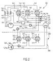
- FIG. 2 depicts, in greater detail, the first stage and part of the second stage of the machine according to a second embodiment of the invention
- FIG. 3 is a thermodynamic diagram for nitrogen N 2 ;
- FIG. 4 is a general operating diagram for a refrigerating machine
- FIG. 5 depicts a typical example of the adsorption curve for a zeolite adsorbent as a function of temperature
- FIG. 6 depicts a three-stage refrigerating machine according to a third embodiment of the invention.
- FIG. 7 depicts a thermodynamic cycle performed by the refrigerating fluid in each stage of the refrigerating machine of FIG. 6 ;
- FIG. 8 is a thermodynamic diagram representing the temperature and pressure conditions in the three stages of the machine of FIG. 6 ;
- FIG. 9 is a schematic depiction of a plate-type heat exchanger
- FIGS. 10 to 12 depict embodiments of a device for breaking up a liquid jet.
- each stage comprises a refrigerating fluid circuit of similar design and operation, in which a vacuum has been created and which will be described in greater detail with reference to the first stage 100 .
- analogous elements bear the same reference numeral increased by one or two hundred.
- the refrigerating fluid is water H 2 O.
- the refrigerating fluid circuit comprises a condenser 101 connected via pipe 104 provided with a circulating pump 102 to an evaporator 103 .
- the evaporator 103 is connected via pipe 110 equipped with an upstream valve 130 to an adsorption/desorption chamber 120 .
- the chamber 120 contains a block of zeolite Z by way of adsorbent.
- the adsorption/desorption chamber 120 is connected via pipe 160 equipped with a downstream valve 150 to the condenser 101 .
- the water is in liquid phase at 1 atmosphere of pressure and at an intermediate temperature of below 100° C., for example of around 80° C.
- the entire refrigerating fluid circuit is under vacuum, for example with a partial pressure of air of below 0.1 millibar (mbar).
- a partial pressure of air of below 0.1 millibar (mbar).
- each adsorption/desorption chamber is connected to a vacuum pump which will be described with reference to FIG. 2 .
- the partial pressures obtained may be monitored using a gas analyzer of known type.
- the water in the liquid phase is injected through the pipe 104 into the evaporator 103 in which it falls as a shower.
- the circulating pump 102 may be replaced by a valve when flow can be obtained under gravity.
- the water By being expanded in the evaporator 103 in a more or less adiabatic manner, the water partially vaporizes.
- the upstream valve 130 is open, the water vapor passes from the evaporator 103 through the pipe 110 to the adsorption/desorption chamber 120 in which the water vapor is adsorbed by the block of zeolite Z.
- This adsorption reaction consumes the water vapor which appears in the evaporator 103 , and this permanently sustains the vaporization of the water in order to compensate for the quantity of vapor adsorbed.
- This continuous vaporization takes heat from the fluid, that is to say the water present in the evaporator 103 , so that a low temperature, for example of between ⁇ 10 and ⁇ 30° C., obtains in the evaporator 103 .
- a phase of solid ice is thus obtained in the bottom of the evaporator 103 .
- the temperature and pressure obtaining in the evaporator 103 may be regulated through, on the one hand, the flow rate of vapor leaving through the upstream valve 130 and, on the other hand, the quantity of liquid water introduced from the condenser 101 and the quantity of heat introduced by the heat exchanger 280 , which will be described later on. Because of the phase equilibrium, the temperature in the evaporator 103 is lower, the lower the pressure maintained. In particular, it might also be possible to obtain a liquid phase in the evaporator 103 by an appropriate choice of temperature and pressure.
- the adsorption/desorption chamber 120 is equipped with a cooling means used to cool the block of zeolite Z during the adsorption reaction, which is exothermal. Thus the temperature in the chamber 120 is kept at below 100° C.
- the cooling means is a circuit of heat transfer fluid 140 equipped with a circulating pump 194 and which is in communication with a cold source 108 which may, for example, be water at ambient temperature or alternatively may be the ambient atmosphere.
- the upstream valve 130 is closed and the downstream valve 150 is opened.
- Some three-way valves 124 are then switched in order to connect the heat transfer fluid circuit 140 to a hot source 109 receiving heat H from outside.
- the hot source 109 may be any heat source at a temperature preferably higher than 250° C.
- the heat transfer fluid circuit 140 acts as a heating means which heats the block of zeolite Z to, for example, 250° C. At this temperature, the adsorptivity of the zeolite is very low. Desorption is prolonged until almost 90% of the water vapor has been desorbed.
- the thermal conductivity of zeolite drops as its water content is reduced, desorbing further water would take a great deal of time, which would slow down the method and thus reduce the temporal efficiency of the machine.
- the water vapor desorbed is removed from the chamber 120 through the pipe 160 , the downstream valve 150 being open.
- the water vapor escapes into the condenser 101 in which it is condensed and cooled to the intermediate temperature of 80 to 100° C.
- the condenser 101 is constantly cooled via a cooling means 126 , for example a heat exchanger connected with atmospheric air.
- a fan 115 is provided to improve the cooling of the condenser 101 .
- the vaporization reaction of the water is used to extract heat from a coil 125 through which a heat transfer fluid circulates.
- the coil 125 belongs to a heat exchanger 280 which also comprises a coil 226 arranged in the condenser 201 of the second stage 200 and a coil 270 arranged in the adsorption/desorption chamber 220 of the second stage 200 .
- the heat exchanger 280 also comprises a circulating pump 227 which circulates the heat transfer fluid from the evaporator 103 into the condenser 201 so as to cool the condenser 201 then into the adsorption chamber 220 so as to cool the block of zeolite Z undergoing adsorption.
- the heat exchanger 380 performs the same function between the second stage 200 and the third stage 300 .
- the refrigerating fluid is, for example, butane C 4 H 10 .
- the intermediate temperature in the condenser 201 is between ⁇ 10 and ⁇ 20° C. at a pressure of 1 or 2 atmospheres, the butane therefore being in the liquid form.
- the temperature obtained in the evaporator 203 is between ⁇ 60 and ⁇ 80° C.
- the temperature is raised to a high temperature of 80° C.
- a heat transfer fluid circuit 240 connected to the hot source 109 and/or some other heating means which will be described with reference to FIG. 2 .
- the stage 200 comprises an intermediate cooling reservoir 216 between the pipe 260 which runs from the chamber 220 and the condenser 201 .
- This reservoir 216 is connected to the condenser 201 via a valve 217 .
- the reservoir 216 is lagged when the fluid desorbed is at a temperature below ambient temperature, to prevent an increase in pressure in the reservoir 216 .
- the reservoir 216 is placed in thermal contact with the ambient atmosphere when the fluid desorbed is at a temperature above ambient temperature, so as to obtain a first cooling of the butane in vapor phase after desorption and thus prevent an increase in pressure in the reservoir 216 .
- the reservoir 216 which is, for example, a conventional steel gas storage cylinder, is positioned outside and a heat exchanger 214 ventilated by a fan 215 is provided.
- the block of zeolite Z in the chamber 220 is heated, for example to 80° C.
- Desorption of the butane causes a rise in pressure in the chamber 220 and therefore causes butane in vapor phase to flow through the pipe 260 to the reservoir 216 .
- this cooling causes butane to be drawn from the chamber 220 .
- the temperature in the reservoir 216 depends on the conditions under which desorption occurs, that is to say in particular on the pressure in the reservoir 216 .
- a pressure of 15 bar may be provided.
- the butane in vapor phase is then expanded through the valve 217 in the condenser 216 in order to be cooled further there and liquefied to a pressure close to normal pressure.
- the stage 300 is similar to the stage 200 .
- the refrigerating fluid is carbon dioxide CO 2 .
- the intermediate temperature in the condenser 301 is between ⁇ 60 and ⁇ 70° C., the carbon dioxide therefore being in the liquid phase.
- the low temperature in the evaporator 303 is between ⁇ 120 and ⁇ 130° C.
- the temperature is raised to a high temperature between ⁇ 10 and ⁇ 20° C.
- heating means of the same type as were used in the second stage 200 namely a heat transfer fluid circuit 340 connected to the hot source 109 or to a heat exchanger associated with an adsorption/desorption chamber of the previous stage, as will be explained with reference to FIG. 2 .
- the temperature in the reservoir 316 has of course to be above ambient temperature, which assumes that a high enough pressure can be had in the reservoir 316 .
- Another option is to perform desorption at a lower pressure, so as to obtain a vapor temperature in the reservoir 316 (or 216 ) which is lower than ambient temperature.
- the exchanger 314 or 214
- the reservoir 316 or 216
- the reservoir 316 is lagged.
- This variant may be preferred, according to the refrigerating fluids used, each time the pressure in the reservoir that would make it possible to obtain a temperature above ambient temperature is so high that it gives rise to unacceptable technological constraints.
- the evaporator of the last stage that is to say the evaporator 303 of the third stage 300 in the exemplary embodiment depicted in FIG. 1 , is provided with means for using the coldness produced by the multi-stage machine.
- a final heat exchanger 80 is arranged between the evaporator 303 of the third stage 300 and a chamber 1 containing the product P that is to be cooled.
- the heat exchanger 80 comprises a heat transfer fluid circuit with a coil 325 in the evaporator 303 in which the heat transfer fluid is cooled and a coil 26 supported in the chamber 1 and in which the heat transfer fluid is heated, cooling the product P.
- the chamber 1 is a storage tank for storing a liquefied gas that is to be cooled in order to compensate for thermal losses through the walls of the chamber 1 .
- a storage tank for storing a liquefied gas that is to be cooled in order to compensate for thermal losses through the walls of the chamber 1 .
- the refrigerating fluids are stored at ambient temperature in the reservoirs 101 , 216 and 316 respectively.
- the stages 100 , 200 and 300 are started in succession.
- the multi-stage machine cannot provide cooling during the phase in which the blocks of zeolite Z are being regenerated.
- FIG. 2 a second embodiment of the machine is now described in which embodiment at least two, and preferably three, adsorption/desorption chambers are provided in each stage.
- elements identical or similar to those of the first embodiment are denoted by the same reference numerals.
- the adsorption/desorption chamber 120 and the corresponding upstream and downstream valves are replaced by three adsorption/desorption chambers 121 , 122 and 123 which are connected respectively to the condenser 101 via pipes 161 to 163 equipped with downstream bars 151 to 153 .
- the chambers 121 to 123 are also connected to the evaporator 103 via pipes 111 to 113 equipped with upstream valves 131 to 133 .
- the valves 131 to 133 and 151 to 153 are electrically-operated valves controlled by a control unit 105 via control lines 107 .
- the control unit 105 is programmed to perform a cycle of concurrent operations in which, simultaneously:
- valves are thus periodically switched in such a way that each chamber performs the adsorption step, the regeneration step and the post-regeneration cooling step in succession.
- the steps are not necessarily of the same duration, which means that the changes in step do not necessarily occur simultaneously in all the chambers of one stage.
- the regeneration step and the cooling step in respect of one chamber are carried out during the adsorption step of the other chamber. In this way, at any moment, there is at least one chamber undergoing adsorption in each stage.
- Each chamber 121 to 123 is equipped with a cooling coil 171 to 173 connected to a cold source and with a heating coil 141 to 143 connected to a hot source.
- a cooling coil 171 to 173 connected to a cold source
- a heating coil 141 to 143 connected to a hot source.
- a single heat transfer fluid circuit may be used as a cooling means and as a heating means by connecting it selectively either to a hot source or to a cold source. Because of the thermal inertia to which this gives rise, such a setup is, however, less advantageous.
- a vacuum pump 106 is connected to each adsorption/desorption chamber 121 to 123 in order to sustain the vacuum.
- the vacuum pump 106 serves to compensate for lacks of leaktightness of the refrigerating fluid circuit and to draw out uncondensable bodies that were initially dissolved in the water, for example oxygen, and which would carry the risk of remaining in the adsorption chamber because they cannot be adsorbed by the zeolite. After one or two cooling cycles, the water will be free of such incondensables.
- the heat exchanger 280 has been depicted in FIG. 2 as being connected to the cooling coil 272 of the adsorption/desorption chamber 22 . However, it is each of the adsorption chambers 221 to 223 that needs to be cooled during the adsorption step and during the post-regeneration cooling step. To achieve that, a separate heat exchanger may be provided for each of the adsorption/desorption chambers 221 to 223 so as to exchange heat with the evaporator 103 . As a variant, the heat exchanger 280 will be equipped with multi-way valves so that the cooling heat transfer fluid can be circulated selectively through one or several cooling coils 272 to 273 .
- a heat exchanger 290 has been depicted which allows a heat transfer fluid to be circulated through a cooling coil 171 of the chamber 121 of the first stage which is undergoing the adsorption step and in which the heat transfer fluid is heated to 80 to 100° C., then through the heating coil 243 of the adsorption/desorption chamber 223 which is undergoing the regeneration step.
- each adsorption/desorption chamber of the second stage can be heated to 80° C. for its regeneration.
- heat exchangers similar to the exchanger 290 may be provided, or alternatively multi-way valves may be provided, these valves being switchable so that one or other of the cooling coils 171 to 173 can be connected selectively to one or other of the heating coils 241 to 243 .
- the heat transfer fluid is circulated through the heat exchanger 290 by means of a pump 294 .
- Heat exchangers similar to the exchangers 280 and 290 depicted in FIG. 2 are connected between all the successive stages of the machine, such that each stage produces the coldness needed to condense the refrigerating fluid in the next stage, to cool the zeolite in the adsorption phase in the next stage, and produces the heat required to perform desorption of the refrigerant in the next stage, or at least some of this heat.
- each stage produces the coldness needed to condense the refrigerating fluid in the next stage, to cool the zeolite in the adsorption phase in the next stage, and produces the heat required to perform desorption of the refrigerant in the next stage, or at least some of this heat.
- only the stage 100 requires an external supply of heat H by means of the hot source 109 .
- external heat H for regeneration in all the stages.
- the machine comprises three stages mounted in cascade. However, it is possible to provide fewer or more stages with, in each stage, a high temperature, an intermediate temperature and a low temperature chosen to be below the corresponding temperature in the previous stage. For example, it is possible to provide a fourth stage using ethylene as a refrigerating fluid, a fifth stage using methane as a refrigerating fluid, a sixth stage using nitrogen or argon as a refrigerating fluid, and a seventh stage using neon as a refrigerating fluid. The low temperature in the last stage could then be close to 10 K.
- Table 1 gives thermodynamic properties of a certain number of bodies that can be used as refrigerating fluids in the multi-stage cooling machine.
- the boiling point of each is given for several pressure values in order to illustrate the range of temperatures that can be obtained in the evaporator for each stage, according to the choice of refrigerating fluid.
- In the first stage it is also possible to use a mixture of water and glycol in order to obtain a higher melting point. Thus, it is possible to avoid ice forming in the evaporator 103 .
- the zeolite Z in the chambers 121 to 123 will then be chosen in a size that prevents any adsorption of the glycol, so that this glycol remains in the evaporator 103 .
- Zeolite is available in numerous forms that differ from one another in terms of their crystal structure or in terms of the pore size. In general, for each cycle, the form of zeolite best suited to the refrigerating fluid used is chosen.
- zeolite that has a particular structure allowing adsorption and desorption reactions to be accelerated is chosen.
- a structure is described in EP-A-470 886.
- Zeolite in granular form, with a diameter of 3 mm for example, is deposited by immersion on a metal component on which projections have been fashioned to delimit interstitial spaces. The zeolite fills these spaces and is fixed by sintering.
- one stage of the machine for example the stage 100 , can be run with just one adsorption/desorption chamber and with the adsorption and desorption steps taking place in quick succession, for example once a minute.
- the cooling machine described hereinabove has numerous applications. For example, it may be used as a cooling unit associated with a tank for transporting liquefied gas in a methane tanker. For that the coil 26 of the final heat exchanger 80 will be suspended in the tank. In order to produce such an arrangement, reference will be made to application FR 2 785 034 A1.
- the temperature in the final heat exchanger 80 must be below or equal to ⁇ 164° C. in order to liquefy methane at normal pressure. To do that, it is of course necessary to provide more stages than have been depicted in FIG. 1 , for example adding a stage using ethylene as a refrigerating fluid and a stage using methane as a refrigerating fluid. For this type of application, the use of oxygen as a refrigerating fluid is avoided, because of the risks of explosion in the event of leakage.
- the multi-stage machine may also be used for carrying out isobaric cooling of a gaseous body that needs to be liquefied in a liquefaction plant.
- the chamber 1 is used as a gas liquefaction chamber.
- the multi-stage machine may be applied to the liquefaction of air or its constituent components, including rare gases.
- the curve C in FIG. 3 represents the thermodynamic path taken by the nitrogen in such a liquefaction method, from the initial state represented by the point A.
- An analogous path may be plotted on the temperature-entropy thermodynamic diagram for another gas, particularly methane.
- Another gas particularly methane.
- Such diagrams are available in the reference work “1′ encyclodozensdie des gaz [encyclopedia of gases]”, ISBN 0-444-41492-4 (1976-2002).
- heat transfer fluid circuits described hereinabove constitute merely one illustrative example of a heat exchanger. Numerous other types of exchanger may be used to implement the method according to the invention, particularly without using an intermediate heat transfer fluid.
- FIG. 6 Another embodiment of a refrigerating machine involving stages is now described with reference to FIG. 6 . Elements identical or analogous to those of the first embodiment bear the same reference number increased by 300.
- a refrigerating fluid performs a thermodynamic cycle the principle of which is represented in FIG. 7 , which is a general diagram that can be applied to various fluids.
- the abscissa axis represents the specific entropy s and the ordinates axis represents the temperature T.
- the line 37 represents the liquid/vapor phase change curve and the line 36 represent the critical isobaric curve for the fluid.
- the fluid in liquid phase is evaporated isobarically at the pressure P 1 and the temperature T 1 by placing it in communication with a zeolite adsorbent that is kept at an adsorption temperature T ads for adsorbing the vapor phase. After adsorption, the zeolite is heated to a desorption temperature T des ⁇ T ads . The desorbed vapor undergoes isobaric compression to the pressure P 2 . The fluid in the vapor phase is condensed isobarically at the pressure P 2 and the temperature T 2 . Finally, the pressure of the liquid phase is reduced sharply from P 2 to P 1 , by means of a pressure drop, thus vaporizing some of the fluid.
- the fluids and the pressures are chosen so that the evaporation of the fluid in a stage of rank n takes the heat necessary for condensing the fluid from the next stage of rank n+1.
- the operating condition is therefore T 1 (n) ⁇ T 2 (n+1).
- FIG. 5 depicts an example of an adsorption curve 39 showing the rate of absorption ⁇ (as a percentage by mass of fluid adsorbed with respect to the quantity of adsorbent) as a function of temperature T. Below the adsorption temperature T ads , the rate is more or less equal to the saturation rate ⁇ 0 . To reduce the adsorption rate to a level ⁇ 1 ⁇ 0 , the temperature of the adsorbent has to be raised to a corresponding desorption temperature T des .
- the curve 39 is dependent upon the fluid/adsorbent pair. In all the stages, the purpose of the adsorption reactors is to provide two vapor pressure levels corresponding to two different temperature levels.
- the fluid is condensed at the high pressure of the cycle Pi through the extraction of the heat of condensation.
- the condensed fluid flows under gravity through a pipe 404 (or 504 or 604 ) to the evaporator 403 (or 503 or 603 ) undergoing a pressure drop to the low pressure of the cycle P 2 .
- Flow through the evaporator occurs naturally on each occasion. All that is required is for its flow rate to be regulated in order to tailor the adsorptivities and evaporation capacities to suit the temperature and pressure conditions desired in the evaporator.
- the evaporator is lagged.
- the condenser 501 (or 601 ) of the next stage in this instance is produced in the form of hollow plates of a heat exchanger which are arranged in the evaporator 403 (or 503 ) and over which the liquid introduced into the evaporator is made to trickle in order simultaneously to evaporate this liquid and condense the refrigerating fluid in the condenser.
- FIG. 9 schematically depicts such a heat exchanger plate 25 on which a film of liquid 27 is undergoing evaporation.
- a jet break-up device 435 (or 535 or 635 ) arranged at the end of the pipe 404 (or 504 or 604 ).
- a pipe 410 (or 510 or 610 ) connects the evaporator to three reactors 421 - 423 (or 521 - 523 or 621 - 623 ) containing a zeolite absorbent.
- Shut-off valves not depicted (for example nonreturn valves), allow the reactors to be isolated individually from the evaporator and from the condenser, so that, at any moment, one of the reactors at least is connected to the evaporator and cooled to an appropriate adsorption temperature T ads so that vapor formed in the evaporator can be absorbed (exothermal reaction), and one of the reactors at least is connected to the condenser and heated to a suitable desorption temperature T des >T ads so as to release the vapor (endothermal reaction) to the condenser at the high pressure of the cycle.
- the thickness e can actually be expressed as a function of the pressure difference ⁇ P between the inside and outside, as follows:
- Table 2 gives, for each stage, a list of bodies that can be used as refrigerating fluid, the high temperature T 2 attained in the condenser and the low temperature T 1 attained in the evaporator.
- the fluids are classified according to their equilibrium temperatures at pressures of 1 bar and 0.5 kPa.
- a three-stage cooling machine with the structure depicted in FIG. 6 was produced.
- the parameters for each stage are given in table 3.
- FIG. 8 provides greater detail about the cycles of the three fluids, with a representation similar to that of FIG. 7 .
- This machine can be used for cooling a product P to ⁇ 150° C. approximately, for example by circulating this product through a heat exchanger 701 housed in the evaporator 603 of the last stage.
- a heat exchanger 480 is provided that allows the heat to be removed to the atmospheric air or to a body of water at ambient temperature.
- a heat source at 250° C. is provided, as described above with reference to FIG. 1 .
- the reactors are cooled in the adsorption phase by a heat exchanger 580 (or 680 ) for removing heat to the evaporator 403 (or 503 ) of the previous stage.
- a heat exchanger 580 or 680
- the heat exchangers 480 , 580 and 680 have been depicted schematically, they comprise the valves and configurations needed to allow each of reactors to be cooled selectively.
- a heat exchanger 540 designed to exchange heat between the atmospheric air, the convection of which is preferably forced by a fan 541 (or 641 ), and the zeolite adsorbent with a view to regenerating it at ambient temperature or a temperature slightly higher than ambient temperature. If the regeneration temperature is higher than the ambient temperature, then in addition heat may be exchanged with the condenser 401 of the water stage in order to provide the additional heat to the zeolite.
- the valves and configurations that allow each of the reactors 521 - 523 (or 621 - 623 ) to be heated selectively are provided. In this way, the supply of external energy to the machine is only to the first stage, when the reactors 421 - 423 are being regenerated.
- a machine for liquefying methane at normal pressure comprises four stages the first three of which are similar to Example 2.
- Table 4 gives the parameters for each stage.
- the exchangers 580 and 680 can be modified in such a way as to cool the reactors undergoing adsorption of the lower stages by using the coldness produced in the evaporator 403 of the water stage. If necessary, for that use may be made of the coldness produced in the evaporator 503 of the butane stage.
- heat exchangers for regenerating the reactors 521 - 523 , 621 - 623 , etc. of the lower stages using the heat of adsorption produced in the reactors 421 - 423 of the water stage, possibly combined with the heat of condensation of the water which is released in the condenser 401 , are provided.
- the reactors of the water stage consume external energy for their regeneration, for example in the form of heat at 250° C.
- Example 3 The machine of Example 3 is sized so that it forms a plant for reliquefying the gas of evaporation loaded on board a methane tanker.
- the useful refrigerating power required is estimated at about 580 kW. For that, the following orders of magnitude are anticipated:
- the total mass of the plant is of the order of 200 t and its daily consumption is 2.7 t/d of methane. These masses are proportional to the cycle time.
- Example 3 The machine of Example 3 is sized to load a methane tanker with a liquefied gas containing a high methane content in 24 h starting out from gases at 30° C. for a cargo volume of 125000 m 3 .
- the useful refrigerating power required is estimated at 630 MW. For that, the following masses of adsorbent are anticipated:
- the total mass of the plant is of the order of 217800 t and its daily consumption is 2940 t/d of methane.
- FIG. 4 is a general operating diagram for a refrigerating machine M.
- the refrigerating machine M transfers heat Q from a cold source to a hot source N the temperature T ch of which is higher than that of the cold source T fr .
- the machine M consumes energy E.
- the efficiency of the machine is defined by the ratio Q/E.
- the cold source consists of a product P that is to be cooled and the hot source preferably consists of the ambient atmosphere or the sea.
- One way of favorably affecting this efficiency is to limit the compression work by limiting the high pressure of the cycles, that is to say the condensation pressure, to a value lower than a few bar, such as in Examples 2 and 3.
- the pressure difference limited to about 1 bar, in each stage, the vapor obtained during regeneration of the zeolite is slightly superheated and does not require any supercooling, because isochoric compression by 1 bar produces a heating effect of just 60° C. approximately.
- Table 5 gives physical properties of various bodies that can be used as refrigerating fluids in the methods according to the invention: critical pressure Pc, critical temperature Tc, triple point temperature and latent heat L, which is a parameter used for classifying the fluids in this table.
- T 1 1 st Water, alcohols ambient Down to ⁇ 40° C. 2 nd Butane, butadiene, ⁇ 20° C. ⁇ 80° C. propadiene, propane 3 rd Ethane, CO 2 ⁇ 80° C. ⁇ 150° C. Nitrous oxide 4 th Methane, krypton ⁇ 150° C. ⁇ 200° C. 5 th Neon, oxygen, ⁇ 200° C. ⁇ 260° C. helium, nitrogen, argon, CO
Landscapes
- Engineering & Computer Science (AREA)
- Physics & Mathematics (AREA)
- Mechanical Engineering (AREA)
- Thermal Sciences (AREA)
- General Engineering & Computer Science (AREA)
- Chemical & Material Sciences (AREA)
- Chemical Kinetics & Catalysis (AREA)
- General Chemical & Material Sciences (AREA)
- Oil, Petroleum & Natural Gas (AREA)
- Sorption Type Refrigeration Machines (AREA)
Applications Claiming Priority (3)
| Application Number | Priority Date | Filing Date | Title |
|---|---|---|---|
| FR03/06839 | 2003-06-06 | ||
| FR0306839A FR2855869B1 (fr) | 2003-06-06 | 2003-06-06 | Procede de refroidissement d'un produit, notamment pour la liquefaction d'un gaz, et dispositif pour sa mise en oeuvre |
| PCT/FR2004/001388 WO2004111556A1 (fr) | 2003-06-06 | 2004-06-04 | Procede de refroidissement d’un produit, notamment pour la liquefaction d’un gaz, et dispositif pour sa mise en œuvre |
Publications (2)
| Publication Number | Publication Date |
|---|---|
| US20060254290A1 US20060254290A1 (en) | 2006-11-16 |
| US7293421B2 true US7293421B2 (en) | 2007-11-13 |
Family
ID=33443188
Family Applications (1)
| Application Number | Title | Priority Date | Filing Date |
|---|---|---|---|
| US10/558,645 Expired - Fee Related US7293421B2 (en) | 2003-06-06 | 2004-06-04 | Method for cooling a product, particularly, for liquefying a gas, and device for implementing this method |
Country Status (13)
| Country | Link |
|---|---|
| US (1) | US7293421B2 (fr) |
| EP (1) | EP1631774B1 (fr) |
| JP (1) | JP4102845B2 (fr) |
| KR (1) | KR100763072B1 (fr) |
| CN (1) | CN100436965C (fr) |
| DE (1) | DE602004008461T2 (fr) |
| EG (1) | EG23850A (fr) |
| ES (1) | ES2289552T3 (fr) |
| FR (1) | FR2855869B1 (fr) |
| NO (1) | NO335703B1 (fr) |
| OA (1) | OA13211A (fr) |
| RU (1) | RU2313740C2 (fr) |
| WO (1) | WO2004111556A1 (fr) |
Cited By (3)
| Publication number | Priority date | Publication date | Assignee | Title |
|---|---|---|---|---|
| WO2013095688A1 (fr) * | 2011-02-17 | 2013-06-27 | Rocky Research | Système de pompe à chaleur à température intermédiaire flottante en cascade |
| US20140053584A1 (en) * | 2010-12-10 | 2014-02-27 | Oliver Tschismar | Climate-control device and method for its operation |
| US20140150491A1 (en) * | 2012-12-04 | 2014-06-05 | Conocophillips Company | Use of low global-warming potential, low ozone depletion potential, low combustibility hydrofluoro-olefin, xenon or iodo compound refrigerants in lng processing |
Families Citing this family (24)
| Publication number | Priority date | Publication date | Assignee | Title |
|---|---|---|---|---|
| JP2009545719A (ja) * | 2006-08-04 | 2009-12-24 | コーニンクレッカ フィリップス エレクトロニクス エヌ ヴィ | 吸着性冷却装置を有する家庭用飲料ディスペンシング装置 |
| FR2909078B1 (fr) * | 2006-11-24 | 2009-01-09 | Inst Francais Du Petrole | Installation de stockage de carburants et procede de remplissage et/ou de vidage des cuves de cette installation |
| TW200837967A (en) * | 2007-03-15 | 2008-09-16 | Motech Ind Inc | Method for bow reduction of composite sheet |
| CN101715535B (zh) | 2007-04-30 | 2012-01-11 | 奥西库尔有限公司 | 摩托车空气调节系统 |
| US20100043462A1 (en) * | 2008-06-10 | 2010-02-25 | Oxicool, Inc. | Air Conditioning System |
| US8425674B2 (en) | 2008-10-24 | 2013-04-23 | Exxonmobil Research And Engineering Company | System using unutilized heat for cooling and/or power generation |
| FR2938003A1 (fr) * | 2008-11-05 | 2010-05-07 | Claude Antoine Blaizat | Procede et dispositif de production d'electricite en utilisant de l'energie thermique a partir d'une source chaude,d'une source froide et d'un gaz moteur. |
| WO2011016809A1 (fr) * | 2009-08-06 | 2011-02-10 | Oxicool, Inc. | Système de conditionnement d'air |
| KR100949946B1 (ko) * | 2009-08-24 | 2010-03-30 | 주식회사 코스모센추리 | 태양광을 이용한 열전대차 발전장치 |
| US8707730B2 (en) * | 2009-12-07 | 2014-04-29 | Alkane, Llc | Conditioning an ethane-rich stream for storage and transportation |
| US8555642B2 (en) * | 2010-03-09 | 2013-10-15 | Exxonmobil Research And Engineering Company | Methods of utilizing waste heat for creating a pressurized working fluid |
| FR2965335A1 (fr) | 2010-09-27 | 2012-03-30 | Gaztransp Et Technigaz | Systeme de refrigeration par adsorption |
| CN102466380A (zh) * | 2010-11-15 | 2012-05-23 | 中兴电工机械股份有限公司 | 吸附式空调设备的控制方法 |
| KR101287975B1 (ko) | 2010-12-21 | 2013-07-22 | 한국과학기술원 | Lng-fpso용 단계형 흡수 및 흡착식 단계형 액화 장치 |
| DE102013114159A1 (de) | 2013-04-12 | 2014-10-16 | Arvid Rauchschwalbe | Verfahren und Vorrichtungen zur Nutzung von thermischer Energie und zur Erzeugung von Temperaturniveaudifferenzen |
| RU2601670C1 (ru) * | 2015-07-22 | 2016-11-10 | Федеральное Государственное Автономное Образовательное Учреждение Высшего Профессионального Образования "Дальневосточный Федеральный Университет" (Двфу) | Холодильная машина |
| AU2016354095B2 (en) | 2015-11-09 | 2019-06-13 | Bechtel Energy Technologies & Solutions, Inc. | Systems and methods for multi-stage refrigeration |
| US20170217592A1 (en) * | 2016-02-01 | 2017-08-03 | General Electric Company | Aircraft Thermal Management System |
| AT518923A1 (de) * | 2016-08-09 | 2018-02-15 | Rep Ip Ag | Transportbehälter |
| FR3059000B1 (fr) * | 2016-11-24 | 2020-01-24 | Centre National De La Recherche Scientifique | Systeme et procede de purification de liquide par osmose inverse. |
| JP2018194194A (ja) * | 2017-05-12 | 2018-12-06 | カルソニックカンセイ株式会社 | 吸着式冷凍システム、および吸着式冷凍システムを備える車両用の空調装置 |
| WO2020242401A1 (fr) * | 2019-05-30 | 2020-12-03 | Maxeff Teknoloji̇ Anoni̇m Şi̇rketi̇ | Système de refroidissement et de chauffage par absorption à efficacité énergétique accrue |
| CN113339905B (zh) * | 2021-05-27 | 2022-09-27 | 五邑大学 | 基于分子筛的空气调节器 |
| US11725858B1 (en) | 2022-03-08 | 2023-08-15 | Bechtel Energy Technologies & Solutions, Inc. | Systems and methods for regenerative ejector-based cooling cycles |
Citations (6)
| Publication number | Priority date | Publication date | Assignee | Title |
|---|---|---|---|---|
| US4827728A (en) | 1986-11-24 | 1989-05-09 | Martin Marietta Energy Systems, Inc. | Seven-effect absorption refrigeration |
| US5339649A (en) | 1991-12-09 | 1994-08-23 | Kabushikikaisha Equos Research | Cryogenic refrigerator |
| US5729988A (en) * | 1974-11-04 | 1998-03-24 | Tchernev; Dimiter I. | Heat pump energized by low-grade heat source |
| US5761925A (en) | 1995-12-21 | 1998-06-09 | Ebara Corporation | Absorption heat pump and desiccant assisted air conditioner |
| US5813248A (en) * | 1995-11-01 | 1998-09-29 | Zornes; David A. | Balanced adsorbent refrigerator |
| EP1111315A2 (fr) | 1999-12-13 | 2001-06-27 | Joh. Vaillant GmbH u. Co. | Pompe à chaleur à adsorption avec plusieurs modules |
Family Cites Families (4)
| Publication number | Priority date | Publication date | Assignee | Title |
|---|---|---|---|---|
| US5598721A (en) * | 1989-03-08 | 1997-02-04 | Rocky Research | Heating and air conditioning systems incorporating solid-vapor sorption reactors capable of high reaction rates |
| SU1719814A1 (ru) * | 1989-12-05 | 1992-03-15 | Институт Тепло-И Массообмена Им.А.В.Лыкова | Адсорбционный холодильник |
| DE4340316C2 (de) * | 1993-11-26 | 1996-03-21 | Daimler Benz Aerospace Airbus | Anordnung zur Kühlung von Lebensmitteln in einem Flugzeug |
| TW421704B (en) * | 1998-11-18 | 2001-02-11 | Shell Internattonale Res Mij B | Plant for liquefying natural gas |
-
2003
- 2003-06-06 FR FR0306839A patent/FR2855869B1/fr not_active Expired - Fee Related
-
2004
- 2004-06-04 OA OA1200500347A patent/OA13211A/fr unknown
- 2004-06-04 JP JP2006508357A patent/JP4102845B2/ja not_active Expired - Fee Related
- 2004-06-04 CN CNB2004800183153A patent/CN100436965C/zh not_active Expired - Fee Related
- 2004-06-04 US US10/558,645 patent/US7293421B2/en not_active Expired - Fee Related
- 2004-06-04 ES ES04767256T patent/ES2289552T3/es not_active Expired - Lifetime
- 2004-06-04 KR KR1020057023362A patent/KR100763072B1/ko not_active Expired - Fee Related
- 2004-06-04 RU RU2005141485/06A patent/RU2313740C2/ru not_active IP Right Cessation
- 2004-06-04 WO PCT/FR2004/001388 patent/WO2004111556A1/fr not_active Ceased
- 2004-06-04 DE DE602004008461T patent/DE602004008461T2/de not_active Expired - Lifetime
- 2004-06-04 EP EP04767256A patent/EP1631774B1/fr not_active Expired - Lifetime
-
2005
- 2005-12-06 EG EGNA2005000791 patent/EG23850A/xx active
-
2006
- 2006-01-03 NO NO20060017A patent/NO335703B1/no not_active IP Right Cessation
Patent Citations (6)
| Publication number | Priority date | Publication date | Assignee | Title |
|---|---|---|---|---|
| US5729988A (en) * | 1974-11-04 | 1998-03-24 | Tchernev; Dimiter I. | Heat pump energized by low-grade heat source |
| US4827728A (en) | 1986-11-24 | 1989-05-09 | Martin Marietta Energy Systems, Inc. | Seven-effect absorption refrigeration |
| US5339649A (en) | 1991-12-09 | 1994-08-23 | Kabushikikaisha Equos Research | Cryogenic refrigerator |
| US5813248A (en) * | 1995-11-01 | 1998-09-29 | Zornes; David A. | Balanced adsorbent refrigerator |
| US5761925A (en) | 1995-12-21 | 1998-06-09 | Ebara Corporation | Absorption heat pump and desiccant assisted air conditioner |
| EP1111315A2 (fr) | 1999-12-13 | 2001-06-27 | Joh. Vaillant GmbH u. Co. | Pompe à chaleur à adsorption avec plusieurs modules |
Cited By (8)
| Publication number | Priority date | Publication date | Assignee | Title |
|---|---|---|---|---|
| US20140053584A1 (en) * | 2010-12-10 | 2014-02-27 | Oliver Tschismar | Climate-control device and method for its operation |
| US9555691B2 (en) * | 2010-12-10 | 2017-01-31 | Robert Bosch Gmbh | Climate-control device and method for its operation |
| WO2013095688A1 (fr) * | 2011-02-17 | 2013-06-27 | Rocky Research | Système de pompe à chaleur à température intermédiaire flottante en cascade |
| US9239174B2 (en) | 2011-02-17 | 2016-01-19 | Rocky Research | Cascade floating intermediate temperature heat pump system |
| US20140150491A1 (en) * | 2012-12-04 | 2014-06-05 | Conocophillips Company | Use of low global-warming potential, low ozone depletion potential, low combustibility hydrofluoro-olefin, xenon or iodo compound refrigerants in lng processing |
| AU2013356460B2 (en) * | 2012-12-04 | 2018-04-05 | Conocophillips Company | Use of low global-warming potential, low ozone depletion potential, low combustibility hydrofluoro-olefin, xenon or iodo compound refrigerants in LNG processing |
| US11885561B2 (en) * | 2012-12-04 | 2024-01-30 | Conocophillips Company | Low global-warming refrigerants in LNG processing |
| US12111102B2 (en) | 2012-12-04 | 2024-10-08 | Conocophillips Company | Mixed refrigerants in LNG cascade |
Also Published As
| Publication number | Publication date |
|---|---|
| JP4102845B2 (ja) | 2008-06-18 |
| NO335703B1 (no) | 2015-01-26 |
| KR20060038942A (ko) | 2006-05-04 |
| CN100436965C (zh) | 2008-11-26 |
| DE602004008461D1 (de) | 2007-10-04 |
| FR2855869B1 (fr) | 2008-01-04 |
| NO20060017L (no) | 2006-03-06 |
| US20060254290A1 (en) | 2006-11-16 |
| KR100763072B1 (ko) | 2007-10-04 |
| EP1631774B1 (fr) | 2007-08-22 |
| EP1631774A1 (fr) | 2006-03-08 |
| RU2005141485A (ru) | 2006-08-27 |
| AU2004247914A1 (en) | 2004-12-23 |
| EG23850A (en) | 2007-10-29 |
| DE602004008461T2 (de) | 2008-05-15 |
| OA13211A (en) | 2006-12-13 |
| ES2289552T3 (es) | 2008-02-01 |
| CN1813161A (zh) | 2006-08-02 |
| RU2313740C2 (ru) | 2007-12-27 |
| FR2855869A1 (fr) | 2004-12-10 |
| JP2006527348A (ja) | 2006-11-30 |
| WO2004111556A1 (fr) | 2004-12-23 |
Similar Documents
| Publication | Publication Date | Title |
|---|---|---|
| US7293421B2 (en) | Method for cooling a product, particularly, for liquefying a gas, and device for implementing this method | |
| EP1062466B1 (fr) | Appareil et procede destines a la refrigeration, a la liquefaction et a la separation des gaz possedant des niveaux de purete variables | |
| US6336331B1 (en) | System for operating cryogenic liquid tankage | |
| CA3171542A1 (fr) | Installation et procede de refrigeration d'hydrogene | |
| US3855810A (en) | One flow cascade cycle with buffer volume bypass | |
| US20230392859A1 (en) | Cryogenic Gas Cooling System and Method | |
| KR20090025514A (ko) | Lng 운반선에 대한 bog 재액화 시스템 | |
| JP4210568B2 (ja) | 冷凍方法及びシステム | |
| CA3254039A1 (fr) | Système et procédé de refroidissement de fluides contenant de l'hydrogène ou de l'hélium | |
| JP2004163089A5 (fr) | ||
| US6598423B1 (en) | Sacrificial cryogen gas liquefaction system | |
| JP2023535569A (ja) | 流体を冷却するための設備及び方法 | |
| JPH1114172A (ja) | ドライアイスの蓄熱を利用する二元冷却設備および 二元冷却方法 | |
| US10240827B2 (en) | Liquid chiller system | |
| SU1019188A1 (ru) | Абсорбционна холодильна установка периодического действи | |
| Chakravarthy et al. | Oxygen liquefier using a mixed gas refrigeration cycle | |
| Longsworth | Sensor cooling at 10 K by Simon expansion of helium | |
| JPH04161770A (ja) | 液化機 | |
| UA103686C2 (uk) | Тепловий насос кріогенного рівня температур |
Legal Events
| Date | Code | Title | Description |
|---|---|---|---|
| AS | Assignment |
Owner name: GAZ TRANSPORT ET TECHNIGAZ, FRANCE Free format text: ASSIGNMENT OF ASSIGNORS INTEREST;ASSIGNORS:MICHALSKI, PIERRE;GOURMELEN, PIERRE;BLAIZAT, CLAUDE;REEL/FRAME:017974/0367;SIGNING DATES FROM 20051103 TO 20051116 |
|
| STCF | Information on status: patent grant |
Free format text: PATENTED CASE |
|
| FEPP | Fee payment procedure |
Free format text: PAYOR NUMBER ASSIGNED (ORIGINAL EVENT CODE: ASPN); ENTITY STATUS OF PATENT OWNER: LARGE ENTITY |
|
| FPAY | Fee payment |
Year of fee payment: 4 |
|
| FPAY | Fee payment |
Year of fee payment: 8 |
|
| FEPP | Fee payment procedure |
Free format text: MAINTENANCE FEE REMINDER MAILED (ORIGINAL EVENT CODE: REM.); ENTITY STATUS OF PATENT OWNER: LARGE ENTITY |
|
| LAPS | Lapse for failure to pay maintenance fees |
Free format text: PATENT EXPIRED FOR FAILURE TO PAY MAINTENANCE FEES (ORIGINAL EVENT CODE: EXP.); ENTITY STATUS OF PATENT OWNER: LARGE ENTITY |
|
| STCH | Information on status: patent discontinuation |
Free format text: PATENT EXPIRED DUE TO NONPAYMENT OF MAINTENANCE FEES UNDER 37 CFR 1.362 |
|
| FP | Lapsed due to failure to pay maintenance fee |
Effective date: 20191113 |