US7293435B2 - Hydraulic distributor for a washing machine - Google Patents
Hydraulic distributor for a washing machine Download PDFInfo
- Publication number
- US7293435B2 US7293435B2 US10/806,892 US80689204A US7293435B2 US 7293435 B2 US7293435 B2 US 7293435B2 US 80689204 A US80689204 A US 80689204A US 7293435 B2 US7293435 B2 US 7293435B2
- Authority
- US
- United States
- Prior art keywords
- pipe
- valve body
- wall
- hydraulic
- distribution nozzle
- Prior art date
- Legal status (The legal status is an assumption and is not a legal conclusion. Google has not performed a legal analysis and makes no representation as to the accuracy of the status listed.)
- Expired - Fee Related, expires
Links
Images


Classifications
-
- D—TEXTILES; PAPER
- D06—TREATMENT OF TEXTILES OR THE LIKE; LAUNDERING; FLEXIBLE MATERIALS NOT OTHERWISE PROVIDED FOR
- D06F—LAUNDERING, DRYING, IRONING, PRESSING OR FOLDING TEXTILE ARTICLES
- D06F39/00—Details of washing machines not specific to a single type of machines covered by groups D06F9/00 - D06F27/00
- D06F39/08—Liquid supply or discharge arrangements
- D06F39/083—Liquid discharge or recirculation arrangements
-
- A—HUMAN NECESSITIES
- A47—FURNITURE; DOMESTIC ARTICLES OR APPLIANCES; COFFEE MILLS; SPICE MILLS; SUCTION CLEANERS IN GENERAL
- A47L—DOMESTIC WASHING OR CLEANING; SUCTION CLEANERS IN GENERAL
- A47L15/00—Washing or rinsing machines for crockery or tableware
- A47L15/42—Details
- A47L15/4214—Water supply, recirculation or discharge arrangements; Devices therefor
-
- Y—GENERAL TAGGING OF NEW TECHNOLOGICAL DEVELOPMENTS; GENERAL TAGGING OF CROSS-SECTIONAL TECHNOLOGIES SPANNING OVER SEVERAL SECTIONS OF THE IPC; TECHNICAL SUBJECTS COVERED BY FORMER USPC CROSS-REFERENCE ART COLLECTIONS [XRACs] AND DIGESTS
- Y10—TECHNICAL SUBJECTS COVERED BY FORMER USPC
- Y10T—TECHNICAL SUBJECTS COVERED BY FORMER US CLASSIFICATION
- Y10T137/00—Fluid handling
- Y10T137/8593—Systems
- Y10T137/87265—Dividing into parallel flow paths with recombining
- Y10T137/87523—Rotary valve
-
- Y—GENERAL TAGGING OF NEW TECHNOLOGICAL DEVELOPMENTS; GENERAL TAGGING OF CROSS-SECTIONAL TECHNOLOGIES SPANNING OVER SEVERAL SECTIONS OF THE IPC; TECHNICAL SUBJECTS COVERED BY FORMER USPC CROSS-REFERENCE ART COLLECTIONS [XRACs] AND DIGESTS
- Y10—TECHNICAL SUBJECTS COVERED BY FORMER USPC
- Y10T—TECHNICAL SUBJECTS COVERED BY FORMER US CLASSIFICATION
- Y10T137/00—Fluid handling
- Y10T137/8593—Systems
- Y10T137/87265—Dividing into parallel flow paths with recombining
- Y10T137/87555—Having direct response valve [e.g., check valve, etc.]
- Y10T137/87563—With reverse flow direction
-
- Y—GENERAL TAGGING OF NEW TECHNOLOGICAL DEVELOPMENTS; GENERAL TAGGING OF CROSS-SECTIONAL TECHNOLOGIES SPANNING OVER SEVERAL SECTIONS OF THE IPC; TECHNICAL SUBJECTS COVERED BY FORMER USPC CROSS-REFERENCE ART COLLECTIONS [XRACs] AND DIGESTS
- Y10—TECHNICAL SUBJECTS COVERED BY FORMER USPC
- Y10T—TECHNICAL SUBJECTS COVERED BY FORMER US CLASSIFICATION
- Y10T137/00—Fluid handling
- Y10T137/8593—Systems
- Y10T137/877—With flow control means for branched passages
- Y10T137/87788—With valve or movable deflector at junction
- Y10T137/8782—Rotary valve or deflector
Definitions
- the present invention relates to hydraulic distributors for electrical appliances such as washing machines.
- Washing machines are known in which the movement of an electromechanical programmer acts on an actuating mechanism, which successively activates the flow of water to the different compartments. Washing machines are also known which use an electronic programmer, which drives a guiding mechanism analogous to that of washing machines with an electromechanical programmer using, for example, a micromotor.
- Washing machines also have a draining function, connecting an emptying pipe to a draining pipe to empty the waste water. Washing machines are known which include a motor pump for this purpose.
- washing machines may include is the re-circulation function, whereby the water is re-circulated from the emptying pipe to the washing machine drum during the washing cycles.
- Washing machines are known which include a second motor pump for carrying out this function and other washing machines are known which use a single motor pump for draining and re-circulating.
- EP 1029965 A1 discloses a hydraulic distributor which comprises a rotating body suitable for selectively distributing the water from an inlet pipe to a plurality of exit pipes connected to the compartments of the tray of the washing machine. Said rotating body turns by motorized means.
- a re-circulation unit which comprises a casing with an emptying pipe, a draining pipe and a re-circulation pipe, and also includes a pivoting flap which can seal off the draining pipe or the re-circulation pipe.
- the flap is moved by the motorized means via intermediate elements that include a lever.
- the main object of the invention is to provide a compact hydraulic distributor with a simple configuration for managing the transmission of water from the mains to the compartments of a washing machine tray and for managing draining and re-circulation.
- the hydraulic distributor of the invention comprises a rotating axle which, with its rotation, directs water from the mains to a plurality of compartments of the washing machine tray, a hydraulic body which comprises an emptying pipe, a draining pipe and an exit pipe for re-circulation, and a valve body housed inside said hydraulic body.
- valve body turns together with the rotating axle. And thus, by the turning action of the rotating axle, as well as directing the water to the different compartments of the washing machine tray, the valve body can also have a first position, in which the flow from the emptying pipe is directed to the draining pipe, and a second position, in which the flow from the emptying pipe is directed to the exit pipe for re-circulation.
- the use of the hydraulic distributor of the invention permits dispensing with the need to use specific devices for draining and re-circulation, as well as the use of more than one electrovalve or more than one motor pump. In this way, the structure and system for connecting the washing machine are simplified, making assembly of the washing machine quicker, and also making significant savings in terms of cost.
- the draining and re-circulation mechanism is integrated within the hydraulic body makes the distributor of the invention compact, robust and easy to assemble.
- FIG. 1 is an exploded view of an embodiment of the hydraulic distributor of the invention.
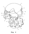
- FIG. 2 is a perspective view of the embodiment of FIG. 1 .
- FIG. 3 is a ground view of the embodiment of FIG. 1 .
- FIG. 4A is a view according to the section IV-IV shown in FIG. 3 , with the valve body in a first position.
- FIG. 4B is a view according to the section IV-IV shown in FIG. 3 , with the valve body in a second position.
- FIG. 5A shows a cross-sectional elevation of the hydraulic body and the valve body of the embodiment in FIG. 1 , said valve body being in a first position.
- FIG. 5B shows a cross-sectional elevation of the hydraulic body and the valve body of the embodiment in FIG. 1 , said valve body being in a second position.
- FIG. 6A is a ground view of the embodiment in FIG. 1 , in which the upper casing has been removed, the valve body being in a first position.
- FIG. 6B is a ground view of the embodiment in FIG. 1 , in which the upper casing has been removed, the valve body being in a second position.
- FIG. 7 shows an embodiment of the valve body of the hydraulic distributor of the invention.
- FIG. 8 shows a first embodiment of the distribution nozzle of the hydraulic distributor of the invention.
- FIG. 9 shows a second embodiment of the distribution nozzle of the hydraulic distributor of the invention.
- the hydraulic distributor 1 of the invention comprises:
- the rotating axle 7 is turned by a motor (not shown in the figures) which is housed in a lower casing 70 and is connected to the rotating axle 7 by gearing means.
- the casing 70 is fixed to a base body 80 onto which the hydraulic body 2 is clipped.
- the rotating axle 7 is attached to the valve body 6 . And thus, via the turning of the rotating axle 7 , the valve body 6 can have a first position, in which the flow from the emptying pipe 10 is directed to the draining pipe 11 , and a second position, in which the flow from the emptying pipe 10 is directed to an exit pipe 15 for re-circulation.
- the water that reaches the hydraulic body 2 from the emptying pipe 10 by the action of an emptying pump (not shown in the figures), is thus directed either to the draining pipe 11 , or to the exit pipe 15 for re-circulation.
- the valve body 6 comprises a wall 60 which seals off the exit pipe 15 for re-circulation when said valve body 6 is in the first position, as shown in FIG. 5A , and which seals off the draining pipe 11 when said valve body 6 is in the second position, as shown in FIG. 5B .
- the hydraulic body 2 comprises a profile 2 b which is substantially cylindrical and coaxial with the rotating axle 7 , and it also comprises an upper surface 2 a .
- the emptying pipe 10 and the exit pipe 15 are joined to said profile 2 b and, as can be seen in FIGS. 5A and 5B , the wall 60 of the valve body 6 rests on the inner surface of said profile 2 b.
- the valve body 6 shown in detail in FIG. 7 , comprises a bushing 61 which is attached to the rotating axle 7 , said bushing 61 being joined to the wall 60 by means of ribs 60 a and 60 b .
- Said valve body 6 also comprises a wall 62 , which is not a sealing wall, positioned symmetrically to the wall 60 with respect to the bushing 61 .
- Said bushing 61 is joined to said wall 62 by means of ribs 62 a and 62 b.
- the wall 60 of the valve body 6 is flexible, whereby said wall 60 fits to the inner surface of the profile 2 b of the hydraulic body 2 , obtaining the best possible seal on the exit pipe 15 for re-circulation or on the draining pipe 11 .
- the wall 62 also rests on the inner surface of the profile 2 b of the hydraulic body 2 . By means of said wall 62 , the valve body 6 can be centred on the inside of the hydraulic body 2 at any time, thus preventing, for example, the pipes 15 and 11 from being sealed incorrectly, due to any gap between the bushing 61 and the rotating axle 7 .
- the wall 62 is not a sealing wall, it allows the water to pass through even though it is facing the pipe 15 or 11 .
- said wall 62 is H-shaped.
- the ribs 60 a and 62 a direct the water from the emptying pipe 10 to the exit pipe 15 when the valve body 6 is in the re-circulation position and, in the same way, the ribs 60 b and 62 b direct the water from the emptying pipe 10 to the draining pipe 11 when the valve body 6 is in the emptying position.
- the hydraulic distributor 1 of the invention also comprises a distribution nozzle 30 which turns together with the rotating axle 7 , said distribution nozzle 30 transmitting the water coming from the mains to the corresponding washing machine compartment depending on its angular position. As can be deduced from FIG. 1 , said distribution nozzle 30 is attached to the valve body 6 .
- the distribution nozzle 30 is on a cup-shaped part 90 which is joined to the upper surface 2 a of the hydraulic body 2 .
- the hydraulic body 2 is fixed between the base body 80 and the cup-shaped part 90 .
- the base body 80 comprises three rods 80 a , 80 b and 80 c which are fixed respectively to three projections 90 a , 90 b and 90 c of the cup-shaped part 90 .
- Said upper casing 100 comprises an inlet pipe 101 from which the water from the mains is transmitted to the distribution nozzle 30 .
- the hydraulic distributor 1 of the invention therefore has a compact, modular configuration. Said hydraulic distributor 1 could also be used in washing machines that do not have a re-circulation system, simply by dispensing with the elements used for said re-circulation.
- the washing machines comprise an overflow safety level detector whereby, if said safety level is exceeded, the emptying pump is activated, draining off the water through the draining pipe.
- the distribution nozzle 30 points towards an area 40 with a hole 41 in its lower part whereby it connects to the draining pipe 11 .
- a valve 42 which seals the hole 41 when there is a flow of water through the draining pipe 11 from the hydraulic body 2 . This therefore prevents water from passing through said hole 41 when the water crosses the draining pipe 11 .
- the valve 42 comprises a flap 43 which pivots with respect to the edge of the hole 41 which is closest to the hydraulic body 2 so that, when there is a flow of water through the draining pipe 11 from said hydraulic body 2 , said flow pushes said flap 43 , making said flap 42 seal the hole 41 .
- a ball valve for example, could also be used.
- the distribution nozzle 30 comprises a central water inlet pipe 31 coaxial with the rotating axle 7 and a water outlet pipe 32 which extends radially from said central pipe 31 .
- the central pipe 31 of the distribution nozzle 30 comprises a substantially horizontal tray 33 in its profile, said tray 33 having an open end 34 under the end of the water outlet pipe 32 . Any water from splashing is collected in said tray 33 .
- Said water flows to the area where the distribution nozzle 30 is pointing through the open end 34 .
- the upper casing 100 comprises a vertical pipe 102 which connects with the inlet pipe 101 and which also connects with the central pipe 31 of the distribution nozzle 30 .
- the distribution nozzle 30 has a labyrinth 35 in its upper part which comprises a circular channel coaxial with the central pipe 31 .
- Said labyrinth 35 faces a labyrinth 104 which contains the upper casing 100 .
- Said labyrinths 35 and 104 contribute to minimize the water leakage through the space between the vertical pipe 102 of the upper casing 100 and the central pipe 31 of the distribution nozzle 30 .
- the tray 33 also collects the water which leaks through the space between the vertical pipe 102 and the central pipe 31 .
- sealing gaskets could also be used to minimize the gap between the distribution nozzle 30 and the upper casing 100 .
- water-tightness between other elements of the hydraulic distributor 1 is achieved via sealing gaskets.
- the water outlet pipe 32 of the distribution nozzle 30 comprises a plate 36 in its profile.
- the function of said plate 36 is to serve as a barrier, collecting the water from any splashing, said water flowing from said plate 36 to where the distribution nozzle 30 is pointing.
- the distribution nozzle 30 in the second embodiment comprises a labyrinth 35 in its upper part.
Landscapes
- Engineering & Computer Science (AREA)
- Textile Engineering (AREA)
- Water Supply & Treatment (AREA)
- Detail Structures Of Washing Machines And Dryers (AREA)
- Cleaning By Liquid Or Steam (AREA)
- Multiple-Way Valves (AREA)
- Treatment Of Fiber Materials (AREA)
Applications Claiming Priority (2)
| Application Number | Priority Date | Filing Date | Title |
|---|---|---|---|
| ESP-200300945 | 2003-04-16 | ||
| ES200300945A ES2238139B1 (es) | 2003-04-16 | 2003-04-16 | "distribuidor hidraulico para una lavadora de ropa". |
Publications (2)
| Publication Number | Publication Date |
|---|---|
| US20040244437A1 US20040244437A1 (en) | 2004-12-09 |
| US7293435B2 true US7293435B2 (en) | 2007-11-13 |
Family
ID=32893066
Family Applications (1)
| Application Number | Title | Priority Date | Filing Date |
|---|---|---|---|
| US10/806,892 Expired - Fee Related US7293435B2 (en) | 2003-04-16 | 2004-03-22 | Hydraulic distributor for a washing machine |
Country Status (5)
| Country | Link |
|---|---|
| US (1) | US7293435B2 (de) |
| EP (1) | EP1469118B1 (de) |
| AT (1) | ATE480658T1 (de) |
| DE (1) | DE602004028983D1 (de) |
| ES (2) | ES2238139B1 (de) |
Cited By (25)
| Publication number | Priority date | Publication date | Assignee | Title |
|---|---|---|---|---|
| US20050284508A1 (en) * | 2004-06-25 | 2005-12-29 | T&P S.P.A. | Device for water supply distribution to a plurality of consumption elements within a washing machine |
| US20070028653A1 (en) * | 2005-08-08 | 2007-02-08 | Thies Edward L | Fluid distribution system |
| US10524634B2 (en) | 2017-09-29 | 2020-01-07 | Midea Group Co., Ltd. | Dishwasher with combined liquid and air sprayers |
| US10531781B2 (en) | 2017-09-29 | 2020-01-14 | Midea Group Co., Ltd. | Dishwasher with discretely directable tubular spray elements |
| US10631708B2 (en) | 2018-09-14 | 2020-04-28 | Midea Group Co., Ltd. | Dishwasher with docking arrangement for elevation-adjustable rack |
| US10765291B2 (en) | 2018-09-14 | 2020-09-08 | Midea Group Co., Ltd. | Dishwasher with check valve in rotatable docking port |
| US11000176B2 (en) | 2018-09-14 | 2021-05-11 | Midea Group Co., Ltd. | Dishwasher with rotatable diverter valve |
| US11026559B2 (en) | 2019-09-30 | 2021-06-08 | Midea Group Co., Ltd. | Dishwasher with image-based fluid condition sensing |
| US11045066B2 (en) | 2019-03-11 | 2021-06-29 | Midea Group Co., Ltd. | Dishwasher with keyed coupling to rack-mounted conduit |
| US11071440B2 (en) | 2018-09-14 | 2021-07-27 | Midea Group Co., Ltd. | Dishwasher with rack-mounted conduit return mechanism |
| US11185209B2 (en) | 2019-11-20 | 2021-11-30 | Midea Group Co., Ltd. | Dishwasher steam generator |
| US11191416B2 (en) | 2019-09-30 | 2021-12-07 | Midea Group Co., Ltd. | Dishwasher with image-based position sensor |
| US11202550B2 (en) | 2019-11-20 | 2021-12-21 | Midea Group Co., Ltd. | Dishwasher thermal imaging system |
| US11259681B2 (en) | 2019-09-30 | 2022-03-01 | Midea Group Co., Ltd | Dishwasher with image-based diagnostics |
| US11399690B2 (en) | 2019-09-30 | 2022-08-02 | Midea Group Co., Ltd. | Dishwasher with cam-based position sensor |
| US11412912B2 (en) | 2020-09-21 | 2022-08-16 | Midea Group Co., Ltd. | Dishwasher with tubular spray element slip ring alignment |
| US11464389B2 (en) | 2019-09-30 | 2022-10-11 | Midea Group Co., Ltd. | Dishwasher with image-based detergent sensing |
| US11484183B2 (en) | 2019-09-30 | 2022-11-01 | Midea Group Co., Ltd. | Dishwasher with image-based object sensing |
| US11484180B2 (en) | 2020-11-11 | 2022-11-01 | Midea Group Co., Ltd. | Dishwasher with tubular spray element including multiple selectable spray patterns |
| US11497374B2 (en) | 2020-02-19 | 2022-11-15 | Midea Group Co., Ltd. | Dishwasher with wall-mounted rotatable conduit |
| US11739851B2 (en) * | 2016-09-08 | 2023-08-29 | Illinois Tool Works Inc. | Clog resistant appliance diverter valve |
| US11826001B2 (en) | 2022-02-15 | 2023-11-28 | Midea Group Co., Ltd. | Dishwasher with tubular spray element including elongated metal tube and retaining tab for mounting support member thereto |
| US12245735B2 (en) | 2022-02-25 | 2025-03-11 | Midea Group Co., Ltd. | Dishwasher including tubular spray element with intermediate support and/or fluid inlet |
| US12290225B2 (en) | 2017-09-29 | 2025-05-06 | Midea Group Co., Ltd. | Dishwasher with walking tubular spray element |
| US12329341B2 (en) | 2023-06-28 | 2025-06-17 | Midea Group Co., Ltd. | Dishwasher with rack-mounted tubular spray element assembly |
Families Citing this family (7)
| Publication number | Priority date | Publication date | Assignee | Title |
|---|---|---|---|---|
| DE102004043838B3 (de) * | 2004-09-08 | 2005-05-25 | Miele & Cie. Kg | Verfahren zum Betreiben einer Waschmaschine |
| ES2278481B1 (es) * | 2004-10-14 | 2008-04-16 | Fagor, S.Coop. | Distribuidor hidraulico para una lavadora de ropa. |
| US20080011338A1 (en) * | 2006-07-16 | 2008-01-17 | Yuyong Zhao | No-spray-arm-rack-based pressure wash system for dishwashers |
| DE102008016171A1 (de) * | 2008-03-28 | 2009-10-01 | BSH Bosch und Siemens Hausgeräte GmbH | Wasserführendes Haushaltsgerät |
| EP2534995A1 (de) * | 2011-06-17 | 2012-12-19 | Etimex Technical Components GmbH | Wasserschalter |
| CN103290657B (zh) * | 2013-05-07 | 2016-03-09 | 无锡小天鹅股份有限公司 | 洗衣机用洗涤剂投放组件及其转向阀 |
| KR102466659B1 (ko) * | 2015-10-07 | 2022-11-11 | 엘지전자 주식회사 | 세탁물 처리기기 |
Citations (3)
| Publication number | Priority date | Publication date | Assignee | Title |
|---|---|---|---|---|
| US3567076A (en) * | 1967-05-20 | 1971-03-02 | Zanussi A Spa Industrie | Rotary distributor assembly for washing machines |
| US4753570A (en) * | 1986-10-14 | 1988-06-28 | Whirlpool Corporation | Bidirectional pump with diaphragm operated valve for dishwasher |
| US5791168A (en) * | 1996-10-30 | 1998-08-11 | Emerson Electric Co. | Apparatus for diverting a flow of water in a washing machine |
Family Cites Families (7)
| Publication number | Priority date | Publication date | Assignee | Title |
|---|---|---|---|---|
| ES280794Y (es) * | 1984-07-31 | 1986-04-16 | Domar, S.A. | Dispositivo distribuidor de agua para maquinas lavadoras de ropa |
| IT1257163B (it) * | 1992-10-23 | 1996-01-05 | Elbi Int Spa | Macchina lavatrice e distributore idraulico per l'impiego in tale macchina. |
| DE29609666U1 (de) * | 1996-05-31 | 1996-08-29 | AEG Hausgeräte GmbH, 90429 Nürnberg | Wasserverteilungseinrichtung für eine Waschmaschine |
| US5848610A (en) * | 1996-11-14 | 1998-12-15 | Livernash; Robert A. | Motorized diverter valve |
| IT1306971B1 (it) * | 1999-01-11 | 2001-10-11 | Elbi Int Spa | Distributore idraulico. |
| FR2790013B1 (fr) * | 1999-02-18 | 2001-05-25 | Siebe Appliance Controls Sa | Distributeur d'eau pour machine a laver |
| ITTO20010943A1 (it) * | 2001-10-05 | 2003-04-05 | Elbi Int Spa | Gruppo valvolare di deviazione, particolarmente per una macchina lava-asciuga-stoviglie. |
-
2003
- 2003-04-16 ES ES200300945A patent/ES2238139B1/es not_active Expired - Fee Related
-
2004
- 2004-02-11 AT AT04380029T patent/ATE480658T1/de not_active IP Right Cessation
- 2004-02-11 ES ES04380029T patent/ES2351486T3/es not_active Expired - Lifetime
- 2004-02-11 DE DE200460028983 patent/DE602004028983D1/de not_active Expired - Lifetime
- 2004-02-11 EP EP20040380029 patent/EP1469118B1/de not_active Expired - Lifetime
- 2004-03-22 US US10/806,892 patent/US7293435B2/en not_active Expired - Fee Related
Patent Citations (3)
| Publication number | Priority date | Publication date | Assignee | Title |
|---|---|---|---|---|
| US3567076A (en) * | 1967-05-20 | 1971-03-02 | Zanussi A Spa Industrie | Rotary distributor assembly for washing machines |
| US4753570A (en) * | 1986-10-14 | 1988-06-28 | Whirlpool Corporation | Bidirectional pump with diaphragm operated valve for dishwasher |
| US5791168A (en) * | 1996-10-30 | 1998-08-11 | Emerson Electric Co. | Apparatus for diverting a flow of water in a washing machine |
Cited By (36)
| Publication number | Priority date | Publication date | Assignee | Title |
|---|---|---|---|---|
| US20050284508A1 (en) * | 2004-06-25 | 2005-12-29 | T&P S.P.A. | Device for water supply distribution to a plurality of consumption elements within a washing machine |
| US20070028653A1 (en) * | 2005-08-08 | 2007-02-08 | Thies Edward L | Fluid distribution system |
| US11739851B2 (en) * | 2016-09-08 | 2023-08-29 | Illinois Tool Works Inc. | Clog resistant appliance diverter valve |
| US11058279B2 (en) | 2017-09-29 | 2021-07-13 | Midea Group Co., Ltd. | Dishwasher with discretely directable tubular spray elements |
| US12290225B2 (en) | 2017-09-29 | 2025-05-06 | Midea Group Co., Ltd. | Dishwasher with walking tubular spray element |
| US10531781B2 (en) | 2017-09-29 | 2020-01-14 | Midea Group Co., Ltd. | Dishwasher with discretely directable tubular spray elements |
| US11800963B2 (en) | 2017-09-29 | 2023-10-31 | Midea Group Co., Ltd. | Dishwasher with discretely directable tubular spray elements |
| US10524634B2 (en) | 2017-09-29 | 2020-01-07 | Midea Group Co., Ltd. | Dishwasher with combined liquid and air sprayers |
| US10631708B2 (en) | 2018-09-14 | 2020-04-28 | Midea Group Co., Ltd. | Dishwasher with docking arrangement for elevation-adjustable rack |
| US10765291B2 (en) | 2018-09-14 | 2020-09-08 | Midea Group Co., Ltd. | Dishwasher with check valve in rotatable docking port |
| US11000176B2 (en) | 2018-09-14 | 2021-05-11 | Midea Group Co., Ltd. | Dishwasher with rotatable diverter valve |
| US11071440B2 (en) | 2018-09-14 | 2021-07-27 | Midea Group Co., Ltd. | Dishwasher with rack-mounted conduit return mechanism |
| US12268347B2 (en) | 2018-09-14 | 2025-04-08 | Midea Group Co., Ltd. | Dishwasher with rotatable diverter valve |
| US11045066B2 (en) | 2019-03-11 | 2021-06-29 | Midea Group Co., Ltd. | Dishwasher with keyed coupling to rack-mounted conduit |
| US11484183B2 (en) | 2019-09-30 | 2022-11-01 | Midea Group Co., Ltd. | Dishwasher with image-based object sensing |
| US11633081B2 (en) | 2019-09-30 | 2023-04-25 | Midea Group Co., Ltd. | Dishwasher with image-based diagnostics |
| US11026559B2 (en) | 2019-09-30 | 2021-06-08 | Midea Group Co., Ltd. | Dishwasher with image-based fluid condition sensing |
| US11464389B2 (en) | 2019-09-30 | 2022-10-11 | Midea Group Co., Ltd. | Dishwasher with image-based detergent sensing |
| US11259681B2 (en) | 2019-09-30 | 2022-03-01 | Midea Group Co., Ltd | Dishwasher with image-based diagnostics |
| US11896182B2 (en) | 2019-09-30 | 2024-02-13 | Midea Group Co., Ltd. | Dishwasher with image-based object sensing |
| US11399690B2 (en) | 2019-09-30 | 2022-08-02 | Midea Group Co., Ltd. | Dishwasher with cam-based position sensor |
| US12042111B2 (en) | 2019-09-30 | 2024-07-23 | Midea Group Co., Ltd. | Dishwasher with cam-based position sensor |
| US11889966B2 (en) | 2019-09-30 | 2024-02-06 | Midea Group Co., Ltd. | Dishwasher with image-based object sensing |
| US11766160B2 (en) | 2019-09-30 | 2023-09-26 | Midea Group Co., Ltd. | Dishwasher with image-based position sensor |
| US11191416B2 (en) | 2019-09-30 | 2021-12-07 | Midea Group Co., Ltd. | Dishwasher with image-based position sensor |
| US12251066B2 (en) | 2019-09-30 | 2025-03-18 | Midea Group Co., Ltd. | Dishwasher with image-based diagnostics |
| US11877711B2 (en) | 2019-09-30 | 2024-01-23 | Midea Group Co., Ltd. | Dishwasher with image-based detergent sensing |
| US11864705B2 (en) | 2019-11-20 | 2024-01-09 | Midea Group Co., Ltd. | Dishwasher thermal imaging system |
| US11202550B2 (en) | 2019-11-20 | 2021-12-21 | Midea Group Co., Ltd. | Dishwasher thermal imaging system |
| US11185209B2 (en) | 2019-11-20 | 2021-11-30 | Midea Group Co., Ltd. | Dishwasher steam generator |
| US11497374B2 (en) | 2020-02-19 | 2022-11-15 | Midea Group Co., Ltd. | Dishwasher with wall-mounted rotatable conduit |
| US11412912B2 (en) | 2020-09-21 | 2022-08-16 | Midea Group Co., Ltd. | Dishwasher with tubular spray element slip ring alignment |
| US11484180B2 (en) | 2020-11-11 | 2022-11-01 | Midea Group Co., Ltd. | Dishwasher with tubular spray element including multiple selectable spray patterns |
| US11826001B2 (en) | 2022-02-15 | 2023-11-28 | Midea Group Co., Ltd. | Dishwasher with tubular spray element including elongated metal tube and retaining tab for mounting support member thereto |
| US12245735B2 (en) | 2022-02-25 | 2025-03-11 | Midea Group Co., Ltd. | Dishwasher including tubular spray element with intermediate support and/or fluid inlet |
| US12329341B2 (en) | 2023-06-28 | 2025-06-17 | Midea Group Co., Ltd. | Dishwasher with rack-mounted tubular spray element assembly |
Also Published As
| Publication number | Publication date |
|---|---|
| EP1469118A3 (de) | 2005-09-14 |
| EP1469118A2 (de) | 2004-10-20 |
| US20040244437A1 (en) | 2004-12-09 |
| ES2238139A1 (es) | 2005-08-16 |
| ES2351486T3 (es) | 2011-02-07 |
| EP1469118B1 (de) | 2010-09-08 |
| ES2238139B1 (es) | 2006-12-01 |
| ATE480658T1 (de) | 2010-09-15 |
| DE602004028983D1 (de) | 2010-10-21 |
Similar Documents
| Publication | Publication Date | Title |
|---|---|---|
| US7293435B2 (en) | Hydraulic distributor for a washing machine | |
| US7607325B2 (en) | Hydraulic distributor for a washing machine | |
| US11739851B2 (en) | Clog resistant appliance diverter valve | |
| US8091569B2 (en) | Water guide for dishwasher | |
| US4467627A (en) | Pump for a dispensing system for an automatic washer | |
| EP2344016B1 (de) | Verfahren und vorrichtung zur beförderung von waschmitteln in einen laugenbehälter einer waschmaschine | |
| US5791168A (en) | Apparatus for diverting a flow of water in a washing machine | |
| JP2009510287A (ja) | 排水出口装置 | |
| AU1641000A (en) | Detergent dispensing method and apparatus for a vertical axis washer | |
| CA1047364A (en) | Liquid flow mechanical diverter valve | |
| US20200208330A1 (en) | Laundry treating appliance and dispenser for treating chemistries | |
| KR20180136109A (ko) | 벽걸이형 세탁기 및 그의 리어 패널 | |
| US12247343B2 (en) | Household appliance with single-use dispenser for bulk dispenser filling | |
| US6206043B1 (en) | CAM operated diverter valve | |
| KR20180136084A (ko) | 벽걸이형 세탁기 및 그의 리어 패널 | |
| KR20180136100A (ko) | 벽걸이형 세탁기 및 벽걸이형 세탁기의 세제함 및 벽걸이형 세탁기의 프론트 패널 | |
| JP3624632B2 (ja) | 切換弁とこれを用いた水洗式大便器 | |
| EP1723888A1 (de) | Geschirrspülmaschine mit automatischer abwechselnder Wasserverteilung | |
| WO2008104829A1 (en) | Laundry washing machine with vent device | |
| US4237919A (en) | Dishwasher inlet air gap | |
| KR20180136110A (ko) | 벽걸이형 세탁기 및 그의 급수 피팅 | |
| KR20180136083A (ko) | 벽걸이형 세탁기 및 그의 급수 밸브 어셈블리 | |
| EP3124673B1 (de) | Waschmaschine mit einer überschwemmungsschutz-sicherheitsvorrichtung | |
| KR950008355B1 (ko) | 식기세척기의 멀티웨이밸브 초기위치 검출장치 | |
| EP4119718B1 (de) | Wäschewaschmaschine mit verbesserten mitteln zum verhindern des rückflusses von wasser |
Legal Events
| Date | Code | Title | Description |
|---|---|---|---|
| AS | Assignment |
Owner name: FAGOR, S. COOP., SPAIN Free format text: ASSIGNMENT OF ASSIGNORS INTEREST;ASSIGNORS:ELEXPURU, ANTON;ARREGI, JON;REEL/FRAME:015132/0972 Effective date: 20040311 |
|
| FEPP | Fee payment procedure |
Free format text: PAYOR NUMBER ASSIGNED (ORIGINAL EVENT CODE: ASPN); ENTITY STATUS OF PATENT OWNER: LARGE ENTITY |
|
| FPAY | Fee payment |
Year of fee payment: 4 |
|
| REMI | Maintenance fee reminder mailed | ||
| LAPS | Lapse for failure to pay maintenance fees | ||
| STCH | Information on status: patent discontinuation |
Free format text: PATENT EXPIRED DUE TO NONPAYMENT OF MAINTENANCE FEES UNDER 37 CFR 1.362 |
|
| STCH | Information on status: patent discontinuation |
Free format text: PATENT EXPIRED DUE TO NONPAYMENT OF MAINTENANCE FEES UNDER 37 CFR 1.362 |
|
| FP | Lapsed due to failure to pay maintenance fee |
Effective date: 20151113 |